Note: Descriptions are shown in the official language in which they were submitted.
CA 02922415 2016-02-25
WO 2015/051854
PCT/EP2013/071323
1
Diagnosis system and diagnosis method
TECHNICAL FIELD
The present disclosure generally relates to a diagnosis system and a diagnosis
method. More specifically, embodiments of the present disclosure relate to a
diagnosis system for detection of keratoconus or other corneal degeneration
impacting the biomechanical stability of the human cornea and a diagnosis
method
for detection of keratoconus or other corneal degeneration impacting the
biomechanical stability of the human cornea. Still more specifically,
embodiments of
the present disclosure relate to a diagnosis system for early detection of
keratoconus
or other corneal degeneration impacting the biomechanical stability of the
human
cornea and a diagnosis method for early detection of keratoconus or other
corneal
degeneration impacting the biomechanical stability of the human cornea.
BACKGROUND
Keratoconus is a degenerative disorder of an eye, which is characterized by a
non-
inflammatory thinning and steepening of the central and/or para-central
cornea.
These structural changes cause the cornea to become of a more conical shape
than
its normal gradual curve and lead to non-reversible visual impairment of the
patient's
eye when untreated. Keratoconus caused structural changes of the cornea also
aggravate or even preclude a LASIK (Laser Assisted in Situ Keratomileusis)
surgery,
since a LASIK treated cornea with a further progressed keratoconus may lead to
a
cornea ectasias later on.
A patient's visual impairment caused by keratoconus may be corrected by
specially
adapted eyeglasses or corneoscleral contact lenses. These corrections,
however, do
not work for a keratoconus in a late stage of its pathogenesis. In this case,
only a so-
called corneal crosslinking can be performed, which may stop or at least
decelerate
the pathogenesis. A complete visual rehabilitation, in turn, is not possible.
Therefore, it is desirable to detect keratoconus as early as possible.
CA 02922415 2016-02-25
WO 2015/051854
PCT/EP2013/071323
2
Besides keratoconus, other corneal degeneration impacting the biomechanical
stability of the human cornea exists. For example, pellucid marginal corneal
degeneration (short: PMD; also known as keratotorus) is a degenerative corneal
condition, which is typically characterized by a clear, bilateral thinning
(ectasia) in the
inferior and peripheral region of the cornea. In particular, the center of the
cornea
shows normal thickness with an intact central epithelium, but the inferior
cornea
exhibits a peripheral band of thinning. The portion of the cornea that is
immediately
adjacent to the limbus is spared, usually a strip of about a few millimeters.
Further,
Bowman's layer of the cornea may be absent, irregular or have ruptured areas.
In the following, the term keratoconus may represent any corneal degeneration
impacting the biomechanical stability of the human cornea. Therefore,
throughout
this specification, the more specific term "keratoconus" may be replaced by
the more
general phrase "corneal degeneration impacting the biomechanical stability of
the
human cornea" or by any term representing corneal degeneration impacting the
biomechanical stability of the human cornea, such as "pellucid marginal
corneal
degeneration".
Existing diagnosis systems and diagnosis methods for detecting keratoconus or
other
corneal degeneration impacting the biomechanical stability of the human cornea
are
merely based on a measuring of the topography of the cornea and a detection of
a
conical deformation in this topography. Therefore, the keratoconus or other
corneal
degeneration impacting the biomechanical stability of the human cornea can
only be
detected in a relatively late stage of the pathogenesis, in which the visual
impairment
of the patient is already advanced.
SUMMARY
In light of the above, there is a need to provide a diagnosis system and a
diagnosis
method, which allow an identification of a structural part of the cornea and
an
identification of a biomechanical property of this structural part of the
cornea. More
specifically, there is a need to provide a diagnosis system and a diagnosis
method,
which allow an early detection of keratoconus or other corneal degeneration
impacting the biomechanical stability of the human cornea.
The present disclosure is based on the following findings:
CA 02922415 2016-02-25
WO 2015/051854
PCT/EP2013/071323
3
To detect keratoconus or other corneal degeneration impacting the
biomechanical
stability of the human cornea in an early stage, it is desirable to acquire
parameters
of the cornea, by which an initiating keratoconus or other corneal
degeneration
impacting the biomechanical stability of the human cornea can be reliably
diagnosed,
before clinically manifested macroscopic structural changes of the cornea
emerge.
The cornea or single parts of the inherent structure of the cornea may be
considered
as a linear-elastic, homogeneous and/or isotropic material. The inherent
structure of
the cornea comprises the corneal epithelium, Bowman's layer (also known as the
anterior limiting membrane), the corneal stroma (also known as substantia
propria),
Dua's Layer, Descemet's membrane (also known as posterior limiting membrane)
and
the corneal endothelium.
For the etiology and during the pathogenesis of keratoconus or other corneal
degeneration impacting the biomechanical stability of the human cornea,
changes of
biomechanical properties of the cornea are most likely to be relevant.
A bio-mechanical property may be represented by an elastomechanical property
and/or a viscoelastic property. These are stiffness related properties. For
example, a
bio-mechanical property may be characterized by one or more of the following
moduli:
= The longitudinal modulus M (also known as the P-wave modulus or the
constrained modulus), which can describe isotropic homogeneous materials. It
may be defined as the ratio of axial stress to axial strain in a uniaxial
strain
state, where all the other non-axial strains are zero (i.e. zero lateral
strain).
= Young's modulus E (also referred to simply as the elastic modulus), which
can
describe tensile elasticity or the tendency of a medium to deform along an
axis, when opposing forces are applied along that axis. It may be defined as
the ratio of tensile stress to tensile strain.
= The shear modulus G (also known as modulus of rigidity, p, mu or Lame's
second parameter), which can describe an object's tendency to shear (the
deformation of shape at constant volume), when acted upon by opposing
forces. It may be defined as shear stress over shear strain. The shear modulus
G may be part of the derivation of viscosity.
= The bulk modulus K, which can describe volumetric elasticity or the
tendency
of a medium to deform in all directions, when uniformly loaded in all
CA 02922415 2016-02-25
WO 2015/051854
PCT/EP2013/071323
4
directions. It may be defined as volumetric stress over volumetric strain or
as
the inverse of compressibility K (or kappa). The bulk modulus K may be
understood as an extension of Young's modulus E to three dimensions.
= Lame's first parameter ALame (or lambda-Lame), which can also describe
tensile
elasticity or the tendency of a medium to deform along an axis, when
opposing forces are applied along that axis.
= Poisson's ratio v (or nu, also known as Poisson number), which can
describe,
when a medium is compressed in one direction, the tendency of the medium
to expand in the other two directions perpendicular to the direction of
io compression. It may be defined as the negative ratio of transverse to
axial
strain or the fraction (or percent) of expansion divided by the fraction (or
percent) of compression.
Stress may be defined as the restoring force caused due to the deformation
divided
by the area, to which the force is applied. Strain may be defined as the ratio
of the
change caused by the stress to the original state of the object.
For a homogeneous isotropic linear elastic medium, relations can be deduced
that
connect the above moduli among each other. For example, the bulk modulus K,
Young's modulus E and the shear modulus G are interlinked via Poisson's ratio
nu:
E 3K - E 3K -2G
v - 2G - 1 - 6K - 6K + 2G. (1)
As a further example, bulk modulus K, shear modulus G and longitudinal modulus
M
are interlinked as follows:
4G
M = K + (2)
3 .
Therefore, when some of the above moduli are known, other unknown moduli may
be calculated therefrom.
To measure a bio-mechanical property, it may be employed a technique based on
Brillouin scattering (short: BS). Brillouin scattering as such is known. In
brief: A
phonon (such as an acoustic mode, i.e. a sound wave) represents position
dependent
mass density variations inside a medium. Because of these local compressions,
the
optical density n (i.e. the index of refraction) of the medium locally
changes. This
leads to a spatially periodic optical density variation, which represents a
diffraction
CA 02922415 2016-02-25
WO 2015/051854
PCT/EP2013/071323
grating for impinging coherent light. Brillouin scattering occurs, when
coherent light
interacts with such a spatially periodic optical density variation by being
deflected or
reflected there off. Since the phonon is traveling within the medium, the
deflected/reflected light is subjected to a Doppler shift. That is, the
Brillouin scattered
5 photons change their energy, wherefore Brillouin scattering is an
inelastic scattering
process. The change in the photon energy corresponds to a change of the
light's
frequency f or the light's wavelength A (wherein f and A are interlinked by
f.A=c/n
with c being the vacuum speed of light and n being the non-disturbed optical
density
of the medium) resulting in a frequency shift fB and a wavelength shift AB up
or down
with respect to the frequency f and the wavelength A of the un-deflected/un-
reflected, i.e. impinging light. Consequently, the frequency of the
inelastically
Brillouin-scattered light is f fB and the wavelength of the inelastically
Brillouin-
scattered light is A AB, respectively, and the spectrum of the Brillouin
scattered light
comprises beside elastically deflected/reflected light forming the so-called
Rayleigh
peak also inelastically Brillouin-scattered light forming at least one
additional side
peak or side band, the so-called Stokes and/or anti-Stokes peak or Stokes
and/or
anti-Stokes Brillouin peak. In general, the Brillouin scattered photons also
change
their propagation direction, wherein the frequency shift fB of the
deflected/reflected
BS light depends on the scattering angle 0 between the impinging un-
deflected/un-
reflected light beam and the deflected/reflected Brillouin scattered light
beam by:
2 = ?I = V
= ___________________________________ cos(0/2) (3)
where:
- n is the local optical density of the medium (when not changed by a phonon),
- V is the velocity of the phonon (i.e. the speed of the sound wave or the
acoustic
velocity in the material; V=A .Q with A being the wavelength of the phonon and
Q
being the frequency of the phonon),
- A is the wavelength of the incidential (e.g., un-deflected/un-reflected)
light wave in
vacuum, and
- S is the scattering angle between the propagation direction of the impinging
incidential (e.g., un-deflected/un-reflected) light wave and the propagation
direction
of the deflected/reflected Brillouin scattered light wave.
Per definition, the propagation direction of the impinging un-deflected/un-
reflected
light wave is anti-parallel to the propagation direction of the
deflected/reflected
Brillouin scattered light wave, when 0 is zero (i.e. 0=00). The "-" sign
corresponds to
CA 02922415 2016-02-25
WO 2015/051854
PCT/EP2013/071323
6
the Stokes Brillouin peak and the "+" sign corresponds to the anti-Stokes
Brillouin
peak, respectively. A frequency shift fB corresponds to a wavelength shift AB
via
IfBlzc'n'IABI/A2 for IABI A.
As the frequency shift fB depends on the scattering angle 8, each scattering
angle 8
relates to a specific frequency shift fB. A maximum/minimum value of the
frequency
shift fB= 2.n.V/A is obtained for 0=0 , corresponding to a Brillouin scattered
light
beam, which is deflected/reflected into the opposite direction of the
impinging un-
scattered/un-deflected/un-reflected light wave. In the case of 8=0 , the
frequency
io shift fB is also called longitudinal Brillouin shift.
By spectroscopically analyzing the Brillouin scattered light beam, bio-
mechanical
properties of the medium can be determined. For example, the complex valued
longitudinal modulus M depends on the velocity of the phonon V by (ReiB et
al.,
15 "Spatially resolved Brillouin spectroscopy to determine the rheological
properties of
the eye lens", Biomedical Optics Express, Vol. 2, No. 8, p. 2144-2159):
Ars
M = A-11 iM2 = p = V2 +t = p = V' = ¨ (4)
fB, ,
where:
- p is the mass density of the medium, in which the phonon propagates, and
- MB is the line width of the Brillouin scattering caused side band of the BS
20 deflected/reflected light beam.
The line width MB corresponds to the reciprocal of the lifetime of the phonon
and
characterizes the attenuation of the phonon (sound wave) during propagation
through the medium. For example, the line width MB may be measured as the full
25 width at half maximum (short: FWMH) of the Stokes or anti-Stokes
Brillouin peak or
any other suitable definition of a spectral width that characterizes a the
frequency
interval, over which the magnitude of all spectral components is equal to or
greater
than a specified fraction of the magnitude of the component having the maximum
value.
When the Brillouin scattered light wave is deflected/reflected into the
opposite
direction of the impinging un-scattered/un-deflected/un-reflected light wave
(i.e.
8=0 ), the shear modulus G does not contribute (i.e. G=0) and the longitudinal
CA 02922415 2016-02-25
WO 2015/051854
PCT/EP2013/071323
7
modulus M equals the bulk modulus K (Le. M=K), compare equation (2). In this
case,
equation (4) becomes:
2 p
M A (5)
4 = ,
and
A2
___________________________________ fm2 = B Afs
(6)
4 .
M1 describes a elastomechanical property of the medium. M2 describes a
viscoelastic
property of the medium.
From equations (5) and (6) it follows: By measuring the frequency shift fB of
one of
the side bands (Stokes or anti-Stokes) of a Brillouin scattered light beam
backscattered from a medium, information can be obtained that relates to an
elastomechanical property of the medium. By measuring the frequency shift fB
of one
of the side bands of a Brillouin scattered light beam backscattered from a
medium
and by measuring the line width Afg of this side band, information can be
obtained
that relates to a viscoelastic property of the medium. More general, by
providing data
that represents the frequency shift fB and/or the line width Mg, information
about
bio-mechanical properties of the medium may be obtained.
In the present disclosure, a diagnosis system and a diagnosis method are
provided.
The diagnosis system comprises an optical coherence tomography (short: OCT)
device, which is configured to emit a first measuring light beam having a
first
wavelength Al. The diagnosis system additionally comprises a Brillouin
scattering
(short: BS) spectrometer, which is configured to emit a second light beam
having a
second wavelength A2, wherein the second wavelength A2 is different from the
first
wavelength Al. The diagnosis system also comprises a beam combiner, which is
configured to combine the first light beam and the second light beam such that
the
first light beam and the second light beam propagate along a same optical path
towards a cornea. The diagnosis system further comprises a beam guiding and
focusing device, which is configured to focus the first light beam and the
second light
beam together at a predetermined position x,y,z on or in the cornea. By and
from the
cornea, the first and the second light beam may at least partially be
deflected/reflected/scattered back into and along the opposite direction of
the first
CA 02922415 2016-02-25
WO 2015/051854
PCT/EP2013/071323
8
and the second light beam that have entered the focus at the predetermined
position
x,y,z on/in the cornea before. The beam combiner splits the first and the
second light
beam backscattered from the cornea such that the first backscattered light
beam
enters the OCT device and the second backscattered light beam enters the BS
s spectrometer. The OCT device is configured to interferometrically analyze
the first
light beam backscattered from the cornea via the beam combiner to provide OCT
data representing a position dependent structural property of the cornea. The
BS
spectrometer is configured to spectroscopically analyze the second light beam
backscattered from the cornea via the beam combiner to provide BS data
representing a position dependent frequency shift fB(x,y,z) of a Brillouin
scattering
caused side band of the backscattered second light beam.
By providing OCT data that represents a position dependent structural property
of
the cornea, spatially resolved information about the local structure of the
cornea may
be obtained. Additionally, by providing BS data that represents the position
dependent frequency shift fB(x,y,z) of the Brillouin scattering caused side
band of the
backscattered second light beam, spatially resolved information about an
elastornechanical and thus a bio-mechanical property of the cornea may be
obtained.
As the first and the second light beam are focused together to the same local
position x,y,z on or in the cornea, the local structure and the bio-mechanical
property
relate to one and the same position x,y,z on/in the cornea. Hence, the
diagnosis
system allows an identification of a structural part of the cornea and an
identification
of a biomechanical property of this structural part of the cornea.
Further, when using the diagnosis system for monitoring the cornea over a
specific
time period, both changes of the structure of the cornea and changes of the
biomechanical property of the cornea can be observed in a spatially resolved
and
locally correlated manner. Such changes may indicate either the integrity of
the
cornea or an initiating or even advanced keratoconus of the cornea.
Consequently,
the diagnosis system allows an early detection of keratoconus or other corneal
degeneration impacting the biomechanical stability of the human cornea.
Further advantages of the diagnosis system are the following: The structural
and bio-
mechanical characterization of the cornea can be performed fast and
contactless, for
example, non-invasive and in-vivo, since it is only based on the emission of
the first
and the second light beam. Furthermore, because of the beam combiner combining
the first and the second light beam, the diagnosis system allows a
simultaneous
CA 02922415 2016-02-25
WO 2015/051854
PCT/EP2013/071323
9
measurement of the structural and biomechanical properties of the cornea. This
not
only reduces the overall diagnosis time, but also ensures a temporal
correlation of
the structural and biomechanical properties of the cornea.
The OCT device may be based on OCT in the Fourier domain (in short: FD-OCT),
on
OCT in the spectral domain (short: SD-OCT) or on OCT employing in a swept-
source
(short: SS-OCT). FD-OCT and SD-OCT typically uses a light source that
continuously
emits broadband light of a particular spectral bandwidth AAi. SS-OCT typically
uses a
light source that is spectrally tunable (i.e. with respect to the wavelength
A1 of the
io emitted light), which instantaneously emits spectrally narrow-band light
and which is
tuned continuously across a spectral bandwidth LS,A1. The first wavelength A1
of the
first light beam may be the central wavelength of the OCT-spectrum, i.e. of
the
spectral bandwidth AAi. The OCT device may have an axial resolution of 10 pm
or
smaller. The OCT device may have a lateral resolution of 100 pm or smaller.
The first
light beam may be a first coherent light beam. The first wavelength A1 of the
first
light beam may be around 800 nm. The spectral bandwidth AA1 of the OCT device
may be around 100 nm.
The OCT device may be configured to interferometrically analyze the first
light beam
backscattered from the cornea via the beam combiner to provide OCT data
representing an image of the cornea at or in the vicinity of the focal
position x,y,z.
The OCT device may be configured to interferometrically analyze the first
light beam
backscattered from the cornea via the beam combiner to provide OCT data
representing a position dependent optical density n(x,y,z) of the cornea (for
example, when n(x,y,z) is not disturbed by a phonon), a position dependent
mass
density p(x,y,z) of the cornea and/or a position dependent reflectivity
r(x,y,z) of the
cornea.
Scattering is a general physical process, where some form of radiation, such
as light,
is forced to deviate from a straight trajectory by one or more localized non-
uniformities in the medium, through which it passes. This may also include
deviation
of reflected radiation, for example, from the angle predicted by the law of
reflection.
In turn, reflection or deflection may represent scattering. In particular, any
light
beam, which is backscattered, may also be considered to be reflected and/or
deflected, and vice versa. In this sense, throughout this specification, the
term
"backscattered" may be replaced by "reflected" and/or by "defleced" or by any
arbitray combination thereof.
CA 02922415 2016-02-25
WO 2015/051854
PCT/EP2013/071323
The BS spectrometer may have a resolution of 100 pm or smaller. The second
light
beam may be a second coherent light beam. The second wavelength A2 of the
(i.e.
un-deflected, un-reflected, un-scattered) second light beam may be around 532
nm.
The line width, for example, the FWHM of the spectral distribution, of the
second
5 light beam may be equal to or smaller than 10 MHz.
The BS spectrometer may be configured to spectroscopically analyze the second
light
beam backscattered from the cornea via the beam combiner to provide BS data
representing also a position dependent line width AfB(x,y,z) of the Brillouin
scattering
10 caused side band of the backscattered second light beam. This
information
represents a viscoelastic property of the cornea. Thus, the diagnosis system
may
allow an identification of a structural part of the cornea and an
identification of not
only an elastomechanical, but also an viscoelastic property of this structural
part of
the cornea.
The beam guiding and focusing device may be configured to adjust the
directional
orientation kx,ky,kz of the first light beam and the second light beam, along
which the
first light beam and the second light beam enter the focus on or in the
cornea. The
BS spectrometer may be further configured to spectroscopically analyze the
second
light beam backscattered from the cornea via the beam combiner to provide BS
data
also representing a direction dependent frequency shift fB(x,y,z,kx,ky,k,) of
the
Brillouin scattering caused side band. In other words: The BS spectrometer may
not
only provide BS data representing a frequency shift f8(x,y,z,kx,ky,kz) of the
Brillouin
scattering caused side band depending on the position of the focus of the
second
light beam, but also depending on the direction, along which the second light
beam
enters the focus. This allows a measuring of an elastomechanical property of
the
cornea in terms of a tensor representation. For example, the position and
direction
resolved measuring of the frequency shift fB(x,y,z,kx,ky,kz) may be used to
calculate a
tensor-modulus such as (M1)1i. As a consequence, an anisotropic
elastomechanical
property of the cornea can be observed, which may give further indication for
an
initiating keratoconus or other corneal degeneration impacting the
biomechanical
stability of the human cornea of the cornea.
The beam guiding and focusing device may be configured to adjust the
directional
orientation kx,ky,kz of the first light beam and the second light beam, along
which the
first light beam and the second light beam enter the focus on or in the
cornea. The
BS spectrometer may be further configured to spectroscopically analyze the
second
CA 02922415 2016-02-25
WO 2015/051854
PCT/EP2013/071323
11
light beam backscattered from the cornea via the beam combiner to provide BS
data
also representing a direction dependent line width AfB(x,Y,z,kx,ky,kz) of the
Brillouin
scattering caused side band. In other words: The BS spectrometer may not only
provide BS data representing a line width LifB(x,y,z,kx,ky,k,) of the
Brillouin scattering
caused side band depending on the position of the focus of the second light
beam,
but also depending on the direction, along which the second light beam enters
the
focus. This allows a measuring of a viscoelastic property of the cornea in
terms of a
tensor representation. For example, the position and direction resolved
measuring of
the frequency shift fB(x,Y,z,kx,ky,kz) and the line width Afs(x,Y,z,kx,ky,kz)
may be used
to calculate a tensor-modulus such as (M2)3i. As a consequence, an anisotropic
viscoelastic property of the cornea can be observed, which may give further
indication for an initiating keratoconus or other corneal degeneration
impacting the
biomechanical stability of the human cornea of the cornea.
The diagnosis system may comprise a control and analysis device. The control
and
analysis device may be configured to control the beam guiding and focusing
device
to scan the predetermined position x,y,z of the focus on or in the cornea in a
one-,
two or- three-dimensional manner and/or to scan the directional orientation
kx,ky,kz
of the first light beam and the second light beam along that the first light
beam and
the second light beam enter the focus on or in the cornea.
The control and analysis device may be configured to calculate a spatially
resolved
topological and/or morphological structure from the OCT data. The control and
analysis device may be configured to generate from the OCT data an image of
the
cornea at or in the vicinity of the focal position x,y,z. Hence, for example,
a
topography or morphology of the cornea may be acquired. Such an acquisition
may
comprise the front and/or back side of cornea or the inherent structure of the
cornea
such as the corneal epithelium, Bowman's layer (also known as the anterior
limiting
membrane), the corneal stroma (also known as substantia propria), Dua's Layer,
Descemet's membrane (also known as posterior limiting membrane) and the
corneal
endothelium.
The control and analysis device may be configured to generate from the OCT
data at
the focal position x,y,z a local optical density n(x,y,z) of the cornea (for
example,
when n(x,y,z) is not disturbed by a phonon), a local mass density p(x,y,z) of
the
cornea and/or a local reflectivity r(x,y,z) of the cornea. For example, the
control and
analysis device may be configured to identify by image processing from the OCT
CA 02922415 2016-02-25
WO 2015/051854
PCT/EP2013/071323
12
data, in which part of the inherent structure of the cornea the focal position
x,y,z is
localized, and to associate for this inherent structural part a corresponding
local
optical density n(x,y,z) of the cornea, a corresponding local mass density
p(x,y,z) of
the cornea and/or a corresponding local reflectivity r(x,y,z) by use of a look-
up table
previously stored in a memory of the control and analysis device. Hence, for
each
point x,y,z within a topography/morphology of the cornea, the corresponding
local
optical density n(x,y,z), local mass density p(x,y,z) and/or local
reflectivity r(x,y,z) of
the cornea can be determined. The control and analysis device may be
configured to
calculate spatially and/or directionally resolved elastomechanical and/or
viscoelastic
properties of the cornea from the BS data. This allows 1D, 2D or 3D OCT
imaging
combined with spatially and/or directionally correlated 1D, 2D or 3D BS
spectroscopy.
Hence, for each point x,y,z within a topography/morphology of the cornea, the
corresponding local elastomechanical and/or viscoelastic properties may be
determined, thus associating the topography/morphology of the cornea with the
rheology of the cornea. As a consequence, a full faced testing of the
integrity of the
cornea can be performed, thereby determining bio-mechanical properties (such
as
the stiffness) of the cornea taking account of the individual structure/form
of the
cornea. For example: Where there is anomaly or deviation in the morphology of
the
examined cornea in comparison to a healthy or normal cornea (such as a locally
thinned out epithelium), precise measurements of the elastomechanical and/or
viscoelastic parameters can be performed in order to monitor any change in the
biomechanical properties.
The control and analysis device may be configured to calculate
p
m _ ____ f B2
4 = 71'
and/or
22 = P
M2¨ 4.nz'fs' Af,5
where:
- M1 is the real part of the complex longitudinal modulus M=M1+iM2 of the
cornea,
" M2 is the imaginary part of the complex longitudinal modulus M=M1+iM2 of the
cornea,
- A2 is the second wavelength of the second light beam,
CA 02922415 2016-02-25
WO 2015/051854
PCT/EP2013/071323
13
- p is the mass density of the cornea,
- n is the optical density of the cornea,
- fB is the frequency shift of the Brillouin scattering caused side band of
the
backscattered second light beam, and
- Afg is the line width of the Brillouin scattering caused side band of the
backscattered second light beam.
For the calculation of M1 and/or M2, the control and analysis device may be
configured to read out a constant mass density n p=p(x,y,z)
=r-constant for the local mass
density p(x,y,z) and/or to read out a constant local optical density
n=n(x,y,z)=nconstant
for the local optical density n(x,y,z) from a memory of the control and
analysis
device. For the calculation of M1 and/or M2, the control and analysis device
may be
configured to generate from the OCT data at the focal position x,y,z a local
optical
density n(x,y,z) of the cornea (for example, when n(x,y,z) is not disturbed by
a
phonon), a local mass density p(x,y,z) of the cornea.
The analysis device may be configured to spatially correlate the OCT data with
the
BS data such that for each spatial position the topological and/or
morphological
structure of the cornea is associated with the corresponding elastomechanical
and/or
viscoelastic properties of the cornea. As a result, of the same area of the
cornea it is
known both the morphology (such as highly resolved local curving, thickness
variations of the stroma, thickness of the epithelium dislocation of Bowman's
membrane and the like) and correlated therewith spatially and/or directionally
resolved elastomechanical and/or viscoelastic parameters. Therefore, spatially
resolved geometry of the cornea can be extracted together with spatially and
directionally resolved stiffness of the cornea.
The beam combiner may be a dichroic mirror or a dispersive optical element
such as
an optical diffraction grating or a prism or the like. The beam combiner may
have a
first reflectivity at least within a first wavelength range R1 covering at
least the first
wavelength A1 of the first light beam and the spectral bandwidth AA1 of the
OCT
device. The minimum value of the first wavelength range R1 may be equal or
smaller
than A1--AA1/2. The maximum value of the first wavelength range R1 may be
equal or
larger than A1-FAA1/2. The beam combiner may have a second reflectivity at
least
within a second wavelength range R2 covering the second wavelength A2 of the
second light beam and a spectral bandwidth AA2. The minimum value of the
second
CA 02922415 2016-02-25
WO 2015/051854
PCT/EP2013/071323
14
wavelength range R2 may be equal or smaller than A2¨AA2/2. The maximum value
of
the second wavelength range R2 may be equal or larger than A2+AA2/2.
The beam combiner may be configured such that the first wavelength range R1
and
the second wavelength range R2 are disjoint. The beam combiner may be
configured
such that the first reflectivity and the second reflectivity are different.
For example,
the first reflectivity of the beam combiner may be around 10% or less, e.g.,
5% or
less, and the second reflectivity of the beam combiner may be around 90% or
more,
e.g., 95% or more, or vice versa. The second spectral bandwidth AA2 may
correspond to around 10, 15, 20, 25, 30, 50 or 100 GHz.
The term reflectivity may represent the reflectance or the fraction of
incident
electromagnetic power reflected. A reflectivity of less than 50% may represent
or be
understood as a transmittance or a transmission. In particular, a value T(A)
of
transmittance or transmission of the beam combiner may be given by 100% minus
a
value R(A) of the reflectivity of the beam combiner, i.e. T(A)=1¨R(A). In
other words:
The beam combiner may be configured such that the absorption of light within
the
beam combiner is small, negligible or even zero. For example, a first
reflectivity of
the beam combiner around 10% or less, e.g., 5% or less, may represent or be
understood as a transmittance or a transmission of the beam combiner around
90%
or more, e.g., 95% or more.
It is pointed out the phrase "vice versa" in "the first reflectivity of the
beam combiner
may be around 10% or less, e.g. 5% or less, and the second reflectivity of the
beam
combiner may be around 90% or more, e.g. 95% or more, or vice versa". This
means that the beam combiner may be configured to combine the first light beam
and the second light beam by transmitting the first light beam and reflecting
the
second light beam. As an alternative, the beam combiner may be configured to
combine the first light beam and the second light beam by reflecting the first
light
beam and by transmitting the second light beam. These alternatives allow a
rearrangement or an interchange of the OCT device and the BS spectrometer.
A diagnosis method comprises the steps of:
- emitting an optical coherence tomography (short: OCT) light beam having a
first
wavelength A1 from an OCT device,
- emitting a second light beam having a second wavelength A2 different from
the first
wavelength A1 from a Brillouin scattering (short: BS) spectrometer,
CA 02922415 2016-02-25
WO 2015/051854
PCT/EP2013/071323
- combining the first light beam and the second light beam by a beam
combiner such
that the first light beam and the second light beam propagate along a same
optical
path towards a cornea,
- focusing the first light beam and the second light beam together at a
5 predetermined position x,y,z on or in the cornea by a beam guiding and
focusing
device,
- interferometrically analyzing the first light beam backscattered from the
cornea via
the beam combiner by the OCT device to provide OCT data representing a
position
dependent structural property of the cornea, and
10 - spectroscopically analyzing the second light beam backscattered from
the cornea
via the beam combiner by the BS spectrometer to provide BS data representing a
position dependent frequency shift fB(x,y,z) of a Brillouin scattering caused
side band
of the backscattered second light beam.
15 To the extent that a diagnosis method or individual steps of a diagnosis
method
is/are described in this description, the diagnosis method or individual steps
of the
diagnosis method can be executed by an appropriately configured diagnosis
system
and/or an individual device of the diagnosis system. Analogous remarks apply
to the
elucidation of the operation mode of a diagnosis system and/or individual
devices of
the diagnosis system that execute(s) diagnosis method steps. To this extent,
apparatus features and method features of this description are equivalent.
Further features, advantages and technical effects of the disclosure will
become
apparent from the following description of exemplary embodiments with
reference to
the accompanying drawings, in which:
Fig. 1 schematically illustrates a diagnosis system,
Fig. 2 schematically illustrates the transmission and reflectivity
of a beam
combiner of the diagnosis system in Fig. 1 (not drawn to scale), and
Fig. 3 schematically illustrates a diagnosis method executed by the
diagnosis
system of Fig. 1.
Fig. 1 shows a diagnosis system 10, which comprises an optical coherence
tomography (short: OCT) device 12, which is configured to emit a first
coherent light
beam 14 having a first wavelength A1 around 800 nm. As an example, the OCT
CA 02922415 2016-02-25
WO 2015/051854
PCT/EP2013/071323
16
device 12 is based on OCT in the Fourier domain (in short: FD-OCT) and
comprises a
light source that emits the first light beam 14 as broadband light of a
particular
spectral bandwidth L,Ai, i.e. the full width at half maximum (short: FVVHM) of
the
spectral distribution of the first light beam 14 is around 100 nm. The first
wavelength
A1 of the first light beam 14 is the central wavelength of the OCT-spectrum,
i.e. of
the spectral bandwidth AA1. The spectral distribution of the first light beam
14 is
schematically illustrated by the dashed lines in Fig. 2. The OCT device has
exemplarily an axial resolution of less than 10 pm.
io The diagnosis system 10 additionally comprises a Brillouin scattering
(short: BS)
spectrometer 16, which is configured to emit a second coherent light beam 18
having
a second wavelength A2 around 532 nm. The FWHM of the spectral distribution of
the
(un-scattered) second light beam 18 is less than 10 MHz. The spectral
distribution of
the (un-scattered) first light beam 18 is schematically illustrated by the dot
lined
peak at A2 in Fig. 2.
A beam combiner 20 of the diagnosis system 10 is configured to combine the
first
light beam 14 and the second light beam 18 such that the first light beam 14
and the
second light beam 18 propagate along a same optical path 22 towards a cornea
24 of
an eye 26.
As an example, the beam combiner 20 is realized as a dichroic mirror. As shown
in
Fig. 2, the beam combiner 20 has a transmission T(A) around 90% or less e.g.,
around 95% or more at least within a first wavelength range R1 covering at
least the
first wavelength A1 of the first light beam 14 and the spectral bandwidth
LS,A1 of the
OCT device 12. The minimum value of the first wavelength range R1 is smaller
than
A1¨AA1/2 and the maximum value of the first wavelength range R1 is larger than
A1-FAA1/2. The beam combiner 20 has a reflectivity R(A) around 90% or more,
e.g.,
95% or more at least within a second wavelength range R2 covering the second
wavelength A2 of the second light beam 18 and a spectral bandwidth AA2. It
applies:
T(A)=1-R(A). The second spectral bandwidth AA2 corresponds to around 30 GHz,
The
minimum value of the second wavelength range R2 is smaller than A2¨AA2/2 and
the
maximum value of the second wavelength range R2 is larger than A2+1A2/2. The
beam combiner 20 is configured such that the first wavelength range R1 and the
second wavelength range R2 are disjoint.
CA 02922415 2016-02-25
WO 2015/051854
PCT/EP2013/071323
17
The diagnosis system 10 further comprises a beam guiding and focusing device
28,
which is arranged in the optical path 22 between the beam combiner 20 and the
cornea 24. The beam guiding and focusing device 28 is configured to focus the
first
light beam 14 and the second light beam 18 together at a predetermined
position
x,y,z on or in the cornea 24. In this sense, the beam guiding and focusing
device 28
is configured to adjust the spatial position x,y,z, where the first light beam
14 and
the second light beam 18 are focused in or on the cornea 24. Additionally, the
beam
guiding and focusing device 28 is configured to adjust the directional
orientation
kx,ky,kz of the first light beam 14 and the second light beam 18, along which
the first
light beam 14 and the second light beam 18 enter the focus on or in the cornea
24 at
the spatial position x,y,z, (compare Figs. 1 and 3).
For example, beam guiding and focusing device 28 comprises a scanning unit 30
with
at least one pair of galvanometer mirrors (not shown) rotatable around two
perpendicularly oriented rotation axis. The scanning unit 30 is configured to
scan the
focal position x,y,z in a two-dimensional manner along spatial directions x
and y
(compare the coordinate system in Figs. 1 and 3). The beam guiding and
focusing
device 28 further comprises an objective 32 for focusing the first light beam
14 and
the second light beam 18 on or in the cornea 24 and for collecting light,
which has
been deflected/reflected/scattered by and from the cornea 24. The objective 32
is
configured such that a lateral resolution of the OCT device 12 and the
resolution of
the BS spectrometer 16 is less than 100 pm, e.g., 50 pm. The focal length of
the
objective 32 is changeable along spatial direction z to scan the focal
position x,y,z in
a one-dimensional manner along spatial direction z (compare again the
coordinate
system in Figs. 1 and 3).
By and from the cornea 24, the first and the second light beam 14, 18 are
partially
deflected/reflected/scattered back into and along the opposite direction of
the first
and the second light beam 14, 18 that have entered the focus at the
predetermined
position x,y,z on/in the cornea 24 before (compare the arrows along 14, 18, 22
in
Fig. 1). The backscattered first and second light beams 14, 18 re-pass through
the
beam guiding and focusing device 28 towards the beam combiner 20. The beam
combiner 20 splits the first and the second light beam 14, 18 backscattered
from the
cornea 24 such that the first backscattered light beam 14 enters the OCT
device 12
and the second backscattered light beam 18 enters the BS spectrometer 16. In
this
sense, the beam combiner 20 is also a beam splitter.
CA 02922415 2016-02-25
WO 2015/051854
PCT/EP2013/071323
18
The OCT device 12 is configured to interferometrically analyze the first light
beam 14
backscattered from the cornea 24 via the beam combiner 20 to provide OCT data
representing a position dependent structural property of the cornea 24. For
example,
the OCT device 12 is configured to provide OCT data representing an image of
the
cornea 24 at or in the vicinity of the focal position x,y,z and to provide OCT
data
representing a position dependent optical density n(x,y,z) of the cornea 24 as
well
as a position dependent mass density p(x,y,z) of the cornea 24.
The BS spectrometer 16 is configured to spectroscopically analyze the second
light
beam 18 backscattered from the cornea 24 via the beam combiner 20 to provide
BS
data representing a position and direction dependent frequency shift fB(x,y,z)
as well
as a position and direction dependent line width AfB(x,y,z) of the Brillouin
scattering
caused side band of the backscattered second light beam 18. The spectral
distribution of the Brillouin scattered second light beam 18 is schematically
illustrated
by the dot lined peak at A2 and the two dot lined side bands/peaks in Fig. 2.
The
frequency shift fB corresponds to a wavelength shift AB via lfd zcn=IABI/A2
and
frequency line width MB corresponds to a wavelength line width LAB via
lAfBlzcrv IAABI/A2 for IABI A=
The diagnosis system 10 also comprises a control and analysis device 34. The
control
and analysis device 34 is connected with the OCT device 12 and the BS
spectrometer
16 via respective connection lines 36 and 38 to control the OCT device 12 and
the BS
spectrometer 16 and to receive the OCT data and the BS data. The control and
analysis device 34 is also connected to the beam guiding and focusing device
28 via
connecting line 40 to control the beam guiding and focusing device 28 such
that the
beam guiding and focusing device 28 scans the predetermined position x,y,z of
the
focus on or in the cornea 24 in a predetermined three-dimensional manner and
also
scans the directional orientation kx,kwkz along that the first light beam 14
and the
second light beam 18 enter the focus on or in the cornea 24 at x,y,z in a
predetermined manner.
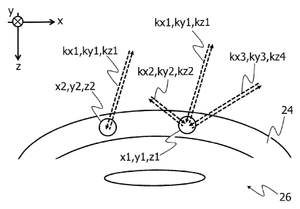
For example, both the first and the second beam 14, 18 are indicated as dashed
arrows in Fig. 3. In a first state of the beam guiding and focusing device 28,
the first
and the second beam 14, 18 enter a first focal position x1,y1,z1 along a first
direction 1(x1,ky1,kz1 and are scattered therefrom back into the opposite
direction of
kx1,ky1,1a1. In a second state of the beam guiding and focusing device 28, the
first
and the second beam 14, 18 enter the first focal position x1,y1,z1 along a
second
CA 02922415 2016-02-25
WO 2015/051854
PCT/EP2013/071323
19
direction 100,1w2,1Q2 and are scattered therefrom back into the opposite
direction of
lo(2,ky2,kz2. In a third state of the beam guiding and focusing device 28, the
first
and the second beam 14, 18 enter the first focal position x1,y1,z1 along a
third
direction lod,ky3,kz3 and are scattered therefrom back into the opposite
direction of
kx3,1w3,1c3. In a fourth state of the beam guiding and focusing device 28, the
first
and the second beam 14, 18 enter a second focal position x2,y2,z2 along the
first
direction kx1,1w1,kz1 and are scattered therefrom back into the opposite
direction of
led,kyl,kz1. The first direction Ic<1,1w1,kz1 may correspond to the x
direction, the
second direction lo<2,1w2,kz2 may correspond to the y direction and the third
direction kx3,ky3,kz3 may correspond to the z direction of the coordinate
system of
the coordinate system as shown in Figs. 1 and 3.
The control and analysis device 34 is configured to calculate a spatially
resolved
topological and morphological structure from the OCT data. For example, the
control
and analysis device 34 is configured to generate from the OCT data an image of
the
cornea 24 at or in the vicinity of the focal position x,y,z. Additionally, the
control and
analysis device 34 is configured to generate from the OCT data at the focal
position
x,y,z a local optical density n(x,y,z) (when n(x,y,z) is not disturbed by a
phonon) and
a local mass density p(x,y,z) of the cornea 24. For example, the control and
analysis
device 34 identifies by image processing from the OCT data, in which part of
the
inherent structure of the cornea 24 the focal position x,y,z is localized, and
associates
for this inherent structural part a corresponding local optical density
n(x,y,z) as well
as a corresponding local mass density p(x,y,z) of the cornea 24 by use of a
look-up
table stored in a memory (not shown) of the control and analysis device 34.
Hence,
for each point x,y,z within a topography/morphology of the cornea, the
corresponding local optical density n(x,y,z) and local mass density p(x,y,z)
of the
cornea 24 is determined.
The control and analysis device 34 is also configured to calculate spatially
and
directionally resolved elastomechanical and viscoelastic properties of the
cornea 24
from the BS data. For example, the control and analysis device 34 calculates
12
P 2
M1 ¨ = f
4. n2 3
and
CA 02922415 2016-02-25
WO 2015/051854
PCT/EP2013/071323
= p
" __________________ = f = Af
4. YI2 8
where:
- M1 is the real part of the complex longitudinal modulus M=M1+iM2 of the
cornea 24,
5 - M2 is the imaginary part of the complex longitudinal modulus M=M1+iM2
of the
cornea 24,
- A2 is the second wavelength of the second light beam 18,
- p=p(x,y,z) is the local mass density of the cornea 24 extracted from the OCT
data,
- n=n(x,y,z) is the local optical density of the cornea 24 also extracted from
the OCT
10 data,
- fB is the frequency shift of the Brillouin scattering caused side band of
the
backscattered second light beam 18 extracted from the BS data, and
- MB is the line width of the Brillouin scattering caused side band of the
backscattered second light beam 18 extracted from the BS data.
The control and analysis device 34 is further configured to spatially
correlate the OCT
data with the BS data such that for each spatial position x,y,z the
topological and
morphological structure of the cornea 24 is associated with the corresponding
elastomechanical and viscoelastic properties of the cornea 24.
As a result, for the same area of the cornea 24 it is known both the
morphology
(such as highly resolved local curving, thickness variations of the stroma,
thickness of
the epithelium dislocation of Bowman's membrane and the like) and correlated
therewith spatially and directionally resolved elastomechanical and
viscoelastic
parameters. Therefore, it can be extracted spatially resolved geometry of the
cornea
24 together with spatially and directionally resolved stiffness of the cornea
24.
Unless expressly stated otherwise, identical reference symbols in the Figures
stand
for identical or identically-acting elements. Also, an arbitrary combination
of the
features and/or modifications elucidated in the Figures in connection with
individual
embodiments is conceivable.