Note: Descriptions are shown in the official language in which they were submitted.
CA 02922534 2016-02-25
WO 2015/034532
PCT/US2013/058743
POWER SYSTEM FOR AN AIRCRAFT WITH DUAL HYBRID ENERGY SOURCES
BACKGROUND OF THE INVENTION
[0001] Power systems, especially power systems in aircraft, manage the
supplying of
power from power sources, such as batteries or generators, to electrical
loads. In aircraft,
gas turbine engines are used for propulsion of the aircraft, and typically
provide
mechanical power which ultimately powers a number of different accessories
such as
generators, starter/generators, permanent magnet alternators (PMA), fuel
pumps, and
hydraulic pumps, e.g., equipment for functions needed on an aircraft other
than
propulsion. For example, contemporary aircraft need electrical power for
avionics,
motors, and other electric equipment. A generator coupled with a gas turbine
engine will
convert the mechanical power of the engine into electrical energy needed to
power
accessories.
BRIEF DESCRIPTION OF THE INVENTION
[0002] A power system for an aircraft having a plurality of power-consuming
components, some of which have transient power requirements, resulting in the
aircraft
having a transient-state power requirement in addition to an average power
requirement,
with the transient-state power requirement being greater than the average
power
requirement. The power system includes at least one generator having a power
output
sufficient to supply the average power requirement, a power distribution buss
coupling
the generator to the power-consuming components, a non-battery power source, a
battery
power source, and a power controller selectively coupling the non-battery
power source
and the battery power source to the power distribution buss to satisfy the
transient power
requirements.
BRIEF DESCRIPTION OF THE DRAWINGS
[0003] In the drawings:
[0004] FIG. 1 is a top down schematic view of the aircraft and power system in
accordance with one embodiment of the invention.
[0005] FIG. 2 is a schematic view of the power system in accordance with one
embodiment of the invention.
1
CA 02922534 2016-02-25
WO 2015/034532
PCT/US2013/058743
[0006] FIG. 3 is a schematic view of the dual hybrid energy system of the
power system,
in accordance with one embodiment of the invention.
[0007] FIG. 4 is a graph showing a transient power response of the power
system, in
accordance with one embodiment of the invention.
DESCRIPTION OF EMBODIMENTS OF THE INVENTION
[0008] The described embodiments of the present invention are directed to an
electrical
power system for an aircraft, which enables production of electrical power
from a turbine
engine, preferably a gas turbine engine.
[0009] As shown in FIG. 1, an aircraft 2 is shown having at least one gas
turbine engine,
shown as a left engine system 12 and a right engine system 14. Alternatively,
the power
system may have fewer or additional engine systems. The left and right engine
systems
12, 14 may be substantially identical, and are shown further comprising power
sources,
such as a dual hybrid energy system (DHES) 16 and at least one electric
machine, such as
a generator 18. The aircraft is shown further comprising a plurality of power-
consuming
components, for instance, an actuator load 26, flight critical loads 27, and
non-flight
critical loads 28. Each of the electrical loads 26, 27, 28 are electrically
coupled with at
least one of the power sources 16, 18 such that the loads 26, 27, 28 are
powered by the
sources 16, 18.
[0010] In the aircraft 2, the operating left and right engine systems 12, 14
provides
mechanical energy which may be extracted via a spool, to provide driving force
for the
generator 18. The generator 18, in addition to the DHES 16, in turn, provides
the
generated power to the electrical loads 26, 27, 28 for load operations. It
will be
understood that while one embodiment of the invention is shown in an aircraft
environment, the invention is not so limited and has general application to
electrical
power systems in non-aircraft applications, such as other mobile applications
and non-
mobile industrial, commercial, and residential applications.
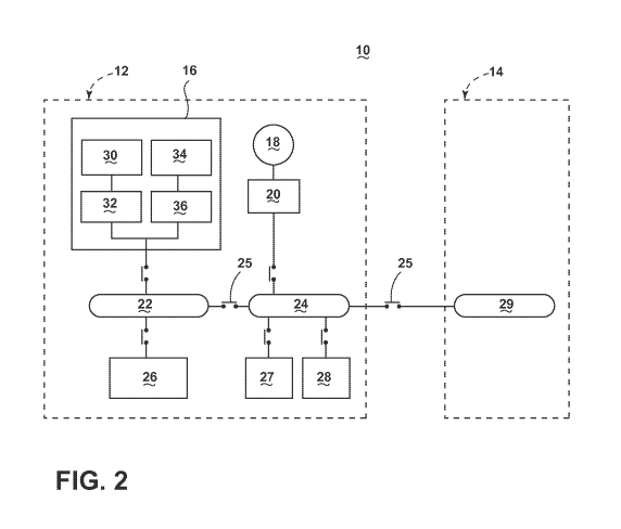
[0011] FIG. 2 illustrates a schematic block diagram of a power system 10 for
an aircraft
having multiple engine systems, shown including the left engine system 12 and
the right
engine system 14. The left and right engine systems 12, 14 may be
substantially
identical; therefore, only the left engine system 12 will be described in
detail for the sake
of brevity, with the understanding the description applies to all the engine
systems.
2
CA 02922534 2016-02-25
WO 2015/034532
PCT/US2013/058743
[0012] The left engine system 12 comprises the DHES 16, at least one generator
18, an
integrated converter/controller (ICC) 20, at least one power distribution
buss, shown
including a first DC power buss 22 and a second DC power buss 24, and the
actuator load
26, flight critical loads 27, and non-flight critical loads 28. The right
engine system 14 is
shown only comprising a DC power buss 29, but may duplicate many of the same
components of the right engine system 12. The first DC power buss 22 is
selectively
coupled with the DHES 16, the actuator load 26, and selectively coupled with
the second
DC power buss 24 via a selectively coupling link 25. The second DC power buss
24 is
further selectively coupled with the generator 18, via the ICC 20, the flight
critical loads
27, the non-flight critical loads 28, and selectively coupled with a
corresponding DC
power buss 29 of the right engine system 14 via a selectively coupling link
25.
[0013] At least a portion of the electrical loads 26, 27, 28 may have steady
state or
average power requirements, and at least a portion of the loads 26, 27, 28 may
have
transient power requirements due to transient operations, such as pulsing
loads or
RADAR. In this sense, the transient power requirements are greater than the
steady-state
or average power requirements. The selectively coupling link 25 may be any
physical or
electrical connection or disconnection device that allows or disallows
electrical coupling
between two components based on, for instance, predetermined characteristics.
In this
example, the selectively coupling link 25 may measure for a threshold voltage
on the first
DC power buss 22. If the measured voltage at the first DC power buss 22 falls
below the
threshold voltage, the selectively coupling link 25 may couple with the second
DC power
buss 24 to allow for sharing voltages between the busses 22, 24.
[0014] The DHES 16 further comprises a non-battery power source, shown as an
ultra-
capacitor 30, sequentially coupled with a power controller, such as a first DC
to DC
converter 32, and a battery power source, shown as a lithium ion (Li-Ion)
battery 34,
sequentially coupled with a second power controller, such as a DC to DC
converter 36.
The first and second DC to DC converters 32, 36 provide a common power output
which
is the output of the DHES 16 selectively coupled with the first DC power buss
22. One
example of the first and/or second DC to DC converter 32, 36 may comprise a
silicon
carbide (SiC) or Gallium Nitride (GaN) based, high bandwidth DC to DC
converter. SiC
or GaN may be selected based on their solid state material construction, their
ability to
handle large power levels in smaller and lighter form factors, and their high
speed
3
CA 02922534 2016-02-25
WO 2015/034532
PCT/US2013/058743
switching ability to perform electrical operations very quickly. Though SiC or
GaN based
DC to DC converters 32, 36 result in smaller and lighter form factors-based DC
to DC
converters may be preferred in cost sensitive applications.
[0015] The ultra-capacitor 30 may be configured to supply large amounts of DC
power
over a very short time before completely discharging, on the order of
hundredths of a
second. As an example, an easily realized 270 volt, 30 farad ultra-capacitor
bank, can
supply 200 kilowatts for greater than 1.0 s. Additionally, the ultra-capacitor
30 may be
recharged and discharged over many cycles without degradation of
charge/discharge
performance. The battery 34, conversely, may be configured to supply DC power
for a
longer period time than the ultra-capacitor 30, and may be recharged and
discharged over
many cycles, but the battery 34 may experience charge/discharge performance
degradation over the many cycle, or over time. As an example, a 270V battery
made
using available 5 ampere-hour cells can supply 50 kilowatt for about 1.8
minutes
[0016] Alternative non-battery and battery power sources are envisioned. For
instance,
an alternate non-battery power source may comprise a fuel cell, or an
emergency non-
battery power source. Additionally, the battery source may comprise the main
aircraft
battery, or an emergency aircraft battery. Furthermore, each of the non-
battery and
battery power sources may comprise more than one source, such as a bank of
capacitors
or a bank of batteries, or any combination of non-battery and battery power
sources.
[0017] The generator 18 is configured to generate a power supply, for example,
an AC
power output, from the mechanical energy supplied by an operating gas turbine
engine.
The AC power output is supplied to the ICC 20, which acts as a rectifier to
rectify the AC
power output to a DC power output, which is further supplied to the second DC
power
buss 24. While a generator 18 is shown, it is envisioned the generator 18 may
alternatively be a starter/generator, which also provides a starting function
for the left
engine system 12. In this embodiment, the DHES may supply power capable of
starting
the left engine system 12 via the starter/generator. In the above example of
the power
system 10, any AC power outputs are rectified to a DC power output, because
the
electrical loads 26, 27, 28 operate on DC power.
[0018] Additionally, both the ultra-capacitor 30 and the battery 34 are
configured to
supply DC power to each of their respective first and second DC to DC
converters 32, 36.
Each DC to DC converter 32, 36 is configured to receive a DC power input,
which may
4
CA 02922534 2016-02-25
WO 2015/034532
PCT/US2013/058743
be variable, and convert it to a known or predetermined DC power output. For
example,
the battery 34 may provide 28 VDC, which may then be converted by the second
DC to
DC converter 36 to a predetermined 270 VDC. Likewise, the ultra-capacitor may
provide
340 VDC, which may then be converted by the first DC to DC converter 32 to 270
VDC.
Alternative configurations are envisioned wherein the ultra-capacitor 30 and
the battery
34 each supply DC power with the same characteristics and only a single DC to
DC
converter 32 is necessary to convert he same DC power input to a predetermined
DC
power output. Additionally, alternate DC power outputs from the ultra-
capacitor 30 and
battery 34, as well as alternative DC power outputs from the first and second
DC to DC
converters 32, 36 are envisioned, so long as the first and second DC to DC
converters 32,
36 supply common DC power outputs.
[0019] The predetermined common DC power output of the first and second DC to
DC
converters 32, 36, and thus, the DC power output from the DHES 16, is supplied
to the
first DC power buss 22. The power system 10 is thus configured such that the
power
supplied by the DHES 16 and the power supplied by the generator 18, via the
ICC 20, is
the same, such as 270 VDC. In this sense, each of the first and second DC
power busses
22, 24 receive a similar DC power supply, and operate with the same electrical
characteristics.
[0020] Each of the first and second DC to DC converters 32, 36 also work in
reverse
operation as well. For instance, if either of the ultra-capacitor 30 and/or
battery 34 has
been discharged, the first DC power buss 22 may selectively supply DC power to
the
respective DC to DC converter 32, 36, which will convert the supplied DC power
to a DC
power output capable of recharging the respective ultra-capacitor 30 and/or
battery 34.
[0021] The first and second DC power busses 22, 24 may also be configured to
selectively couple with each other, via a selectively coupling link 25, or
selectively
couple with the DC power busses 29 of the right engine system 14, via a
selectively
coupling link 25, to share a common DC power supply to power system electrical
loads
26, 27, 28 (or any loads of the right engine system 14), during times where
the respective
power sources 16, 18 cannot provide sufficient power outputs to power all of
the loads
26, 27, 28 simultaneously. Additionally, one or more of the first and second
DC power
busses 22 may be configured to cut or stop supplying the DC power output to
non-flight
CA 02922534 2016-02-25
WO 2015/034532
PCT/US2013/058743
critical loads 28, in the event that insufficient power is supplied from the
DHES 16 and
generator 18 to power all of the electrical loads 26, 27, 28 simultaneously.
[0022] Each of the first and second DC power busses 22, 24 may be further
configured to
convert the DC power input to a different DC power output, as required by the
electrical
loads 26, 27, 28. For example, several non-flight critical loads 28 may
operate by 28
VDC. In this example, the second DC power buss 24 may be configured to convert
the
270 VDC power input to 28 VDC before selectively supplying it to the non-
flight critical
loads 28.
[0023] FIG. 3 illustrates a more detailed schematic view of the DHES 16. As
shown, the
DHES 16 further comprises a load spectrum selection filter 38, and each of the
first and
second DC to DC converters 32, 36 further comprises a respective first and
second
controller 40, 42. The DHES 16 allows for data communications, represented as
dotted
lines, such that the first controller 40 sends and receives a command signal
46 to and from
the second controller 42, receives an ultra-capacitor status signal 48,
representative of the
current status of the ultra-capacitor 30, for instance as the amount of power
in the ultra-
capacitor 30, from the ultra-capacitor 30, and receives a first filter signal
52 from the load
spectrum selection filter 38. The DHES 16 further allows for data
communications such
that the second controller 42 receives a battery status signal 50,
representative of the
current status of the battery 34, for instance as the amount of power in the
battery 34,
from the battery 34, and a second filter signal 54 from the load spectrum
selection filter
38.
[0024] The load spectrum selection filter 38 is additionally shown receiving a
DC power
buss signal 44 from the first DC power buss 22, representative of the
instantaneous and
collective DC power busses 22, 24 energy requirements. Alternatively, the load
spectrum
selection filter 38 may further receive signals from each DC power buss 22, 24
with each
signal being representative of each DC power buss 22, 24 energy requirements
to supply
the electrical loads 26, 27, 28. In this example, the load spectrum selection
filter 38 may
summate the energy requirements of all the DC power busses 22, 24 providing
signals.
Whereas the dotted lines represent data communications, the solid lines of
FIG. 3
represent power couplings such that each of the ultra-capacitor 30 and battery
34 allow
for bi-directional power transmission to and from each respective first and
second DC to
6
CA 02922534 2016-02-25
WO 2015/034532
PCT/US2013/058743
DC converter 32, 36, and each converter 32, 36 allows for selective bi-
directional power
transmission to and from the first DC power buss 22.
[0025] The power system 10 operates to supply the average and transient power
requirements to the electrical loads 26, 27, 28. In one embodiment of the
invention, the
generator 18 is designed, sized, and configured to provide a power output
sufficient to
supply the average power requirements of the power system 10, but it may not
be
designed, sized, and configured to provide a power output sufficient to supply
the
transient power requirements of the system 10. Stated another way, the
generator 18
power output may be insufficient to power the transient power requirements of
the power
system 10.
[0026] During the transient power requirements, additional power is supplied
to at least
one of the first or second DC power busses 22, 24 by the DHES 16 to account
for the
transient power requirements. The combination of power supplied by the
generator 18
and the DHES 16 is sufficient to account for the transient power requirements
with the
split determined to maximize the system performance such as minimizing its
weight,
maximizing its life etc. This occurs when at least one of the first and/or
second DC
power busses 22, 24 senses a transient power requirement occurring (i.e. the
busses 22, 24
senses insufficient power is being supplied to the electrical loads 26, 27,
28). At this
time, the first and/or second DC power busses 22, 24 sends the DC power buss
signal 44,
representing that the buss 22, 24 has an insufficient, or close to
insufficient amount of
power supply to power the electrical loads 26, 27, 28.
[0027] The DHES 16 operates to selectively supply power to the first DC power
buss 22
in response to the DC power buss signal 44. This occurs when the load spectrum
selection filter 38 first receives the DC power buss signal 44 representing
the
instantaneous energy requirements of the DC power busses 22, 24. The load
spectrum
selection filter 38 operates, for example, as a low pass filter to operatively
remove the
slowly varying energy requirements of the DC power buss signal 44. Stated
another way,
the load spectrum selection filter 38 removes the average power requirements
from the
energy requirements of the DC power busses 22, 24, leaving only the transient
power
requirements of the electrical loads 26, 27, 28. The transient power
requirements of the
DC power busses 22, 24, and are provided from the filter 38 to each of the
first and
second controllers 40, 42 as the first and second filter signals 52, 54.
Alternatively, the
7
CA 02922534 2016-02-25
WO 2015/034532
PCT/US2013/058743
load spectrum selection filter 38 may operate such that only transient power
requirements
over a predetermined or dynamic threshold will be provided as the first and
second filter
signals 52, 54.
[0028] The first and second controllers 40, 42 are in bi-directional
communication with
each other such that they may cooperatively control each respective first and
second DC
to DC converter 32, 36 to provide a sufficient DC power output from the DHES
16 to
account for the increased transient power requirements. In one example, the
load is
pulsing from no load to 240kW. The average load power is approximately 100
kilowatts,
which is supplied by the generator. When the load pulse occurs the first and
second filter
signals 52, 54 are provided to each respective first and second controllers
40, 42,
indicating that the first DC power buss 22 needs to provide an additional 140
kilowatts of
power due to transient power requirements above the average value. The first
controller
40 may receive the ultra-capacitor status signal 48, indicating that the ultra-
capacitor 30
may provide 120 kilowatts of power by discharging. The second controller 42
may
receive the battery status signal 50 indicating the battery 34 may provide 20
kilowatts of
power by discharging.
[0029] The bi-directional communication between the first and second
controllers 40, 42
determines how much additional power each of the ultra-capacitor 30 and
battery 34 will
provide to account for the transient power requirements. In this example, the
first
controller 40 may determine the ultra-capacitor 30 will discharge the full 120
kilowatts,
and may instruct the second controller 42 to discharge 20 kilowatts from the
battery 34.
In another example, each of the ultra-capacitor 30 and battery 34 may
discharge 70
kilowatts, or the battery 34 may discharge 120 kilowatts while the ultra-
capacitor
discharges 20 kilowatts. These instances are non-limiting examples of DHES 16
operation.
[0030] The DHES 16 may operate such that the first controller 40 discharges
the ultra-
capacitor 30 whenever possible to account for as much of the transient power
requirements as possible. In another instance, if 400 Watts of transient power
requirements are needed, and the ultra-capacitor is capable of discharging 800
Watts, the
first controller 40 will discharge the ultra-capacitor 30, and the battery 34
will not be
discharged at all. Similarly, in another instance, if 800 Watts of transient
power
requirements are needed, and the ultra-capacitor may discharge 800 Watts, the
first
8
CA 02922534 2016-02-25
WO 2015/034532
PCT/US2013/058743
controller 40 will discharge the ultra-capacitor 30, and the battery 34 will
not be
discharged at all. In this example, only in instances where the discharging of
the ultra-
capacitor 30 will be insufficient to account for the transient power
requirements will the
battery 34 be discharged. Stated another way, the power system 10 may
selectively
couple the ultra-capacitor 30 to at least one of the first or second DC power
busses 22, 24
prior to selective coupling of the battery 34 to the busses 22, 24. This
priority of
providing power during transient power requirements allows the power system 10
to
repeatedly provide additional sufficient power for the aircraft while actively
preventing
degradation of charge/discharge performance of the battery 34, by only
discharging the
battery 34 when necessary to supplement the ultra-capacitor 30 discharge.
[0031] With a steady or average load, the first and/or second DC power busses
22, 24
send the DC power buss signal 44 to the load spectrum selection filter 38. The
filter 38
thus generates the first and second filter signals 52, 54 indicative that
power system 10 is
operating with an average power requirement. Each controller 40, 42 also
receives the
respective ultra-capacitor status signal 48 and battery status signal 50. In
the event either
the ultra-capacitor status signal 48 or battery status signal 50 indicates the
respective
power source is not fully charged, the respective first or second controller
40, 42
selectively operates the respective first or second DC to DC converter 32, 36
to allow for
the first DC power buss 22 to provide a DC power output which is converted to
the
proper DC voltage, to charge the respective source 30, 34. Once the ultra-
capacitor 30
and/or battery 34 is fully charged, the DHES 16 awaits a transient power
requirement.
[0032] FIG. 4 illustrates the power requirements of the power system 10 during
a
transient power requirement 60 followed by a steady-state power requirement
62. In this
graph, "P bat" represents the power discharge of the battery 34, "P ultrac"
represents the
power discharge of the ultra-capacitor 30, "P DHES" represents the power
discharge of
the DHES 16, and "P load" represents the power requirements of the transient
electrical
load or loads. As shown, at time to, no transient power requirements 62 exist.
At time -11,
a positive power transient occurs, and the DHES 16 begins supplying
supplemental power
to account for the transient power requirement 60. As shown, the majority of
the
supplemental power supplied comes from the ultra-capacitor 30 discharge in
this
embodiment of the invention. In between times ti and t2, while the transient
power
requirement 60 remains constant, the ultra-capacitor 30 discharges such that
it supplies a
9
CA 02922534 2016-02-25
WO 2015/034532
PCT/US2013/058743
large amount of supplemental power. During this same period, the battery 34 is
shown
supplying a small fraction of the power supplied by the ultra-capacitor 30 to
reduce
battery stress and maximize battery life.
[0033] At time t2, the load undergoes a new transient when it decreases to
zero load, and
thus, the power system is operating with an average power requirement 62.
During this
time, the DC power busses 22, 24 supply power to recharge the ultra-capacitor
30 and
battery 34, shown having a negative power value due to recharging, as the DHES
16 tries
to keep the load on the generator equal to the value just prior to the t2 load
reduction
transient. The graph in FIG. 4 illustrates one example of the power system 10
operations,
and other operations are envisioned. In a typical generator 18, even an
oversized
generator capable of providing sufficient power to account for the transient
power
requirement, the generator 18 may not be able to respond fast enough to the
transient
power requirement, which may occur, for instance, for only several hundredths
of a
second.
[0034] Many other possible embodiments and configurations in addition to that
shown in
the above figures are contemplated by the present disclosure. For example, one
embodiment of the invention contemplates more than one generator 18 per engine
system
12, 14. In another embodiment of the invention, the power system 10 may
incorporate an
emergency power system, wherein the DHES may provide emergency power during
emergency operation. In yet another embodiment of the invention, the second
filter
signal 54 may be eliminated, and the first controller 40 may receive the first
filter signal
52, and then instruct the second controller 42 how to operate based on the
amount of
power the ultra-capacitor may supply. In yet another embodiment of the
invention, the
first and second controllers 40, 42 may be replaced by a single controller
which controls
all aspects controlled by both controllers 40, 42, and may additionally be
located in an
alternative location than disclosed, for example, as part of the filter 38, or
DC power
busses 22, 24. Additionally, any of the aforementioned signals 44, 48, 50, 52,
54 may be,
for instance, based on commonly used signal polling systems, or on a commonly
used
signal trigger systems. Additionally, the design and placement of the various
components
may be rearranged such that a number of different in-line configurations could
be
realized.
CA 02922534 2016-02-25
WO 2015/034532
PCT/US2013/058743
[0035] In yet another embodiment of the invention, it is envisioned that the
DC power
busses 22, 24 may alternatively be configured as one or more AC power busses,
and the
electrical loads 26, 27, 28 operate on AC power. In this embodiment, each of
the ultra-
capacitor 30, battery 34, and generator 18 will be configured with proper
converters
and/or inverters to be able to provide AC power at a proper voltage and
frequencies to the
AC power busses. Additionally, the converters and/or inverters selectively
coupling
ultra-capacitor 30 and battery 34 the to the AC power busses may be configured
to allow
for reverse conversion, so that each of the ultra-capacitor 30 and battery 34
may be
charged.
[0036] The embodiments disclosed herein provide a power system for an aircraft
configured to supply additional power to account for transient power
requirements.
When designing aircraft components, important factors to address are size,
weight, and
reliability. One advantage that may be realized in the above embodiments is
that the
above described embodiments have superior weight and size advantages over the
conventional type power systems. To provide a generator (alone) to account for
the
transient power requirements, the generator would need to be larger, resulting
in
increased size and weight. This increased size and weight may not be desirable
for the
transient power modes, which may occur infrequently. By allowing for a DHES to
provide for supplemental power during transient power requirements, the
configuration
may allow for a smaller and/or lighter generator which only has to supply
average power
requirements, rather than scale up to a larger and heavier generator to
account for stresses
on the power supply due to transient power requirements. The DHES also allows
for a
faster response than a typical generator, when supplying the additional power
to the
power system. Additionally, a smaller and/or lighter generator allows for an
extended life
of operation, which increases reliability of the system, and reduces
maintenance and
replacement costs. Reduced weight and size correlate to competitive advantages
during
flight.
[0037] Additionally, another advantage of the above described embodiments
allows for
less degradation in charging and discharging performance of the battery due to
the
priority discharging of the ultra-capacitor during transient power
requirements. Less
degradation of battery performance from the charging and discharging stresses
of use
11
CA 02922534 2016-02-25
WO 2015/034532
PCT/US2013/058743
increases the reliability and longevity of the battery system of the aircraft
and reduces
maintenance and replacement costs.
[0038] To the extent not already described, the different features and
structures of the
various embodiments may be used in combination with each other as desired.
That one
feature may not be illustrated in all of the embodiments is not meant to be
construed that
it may not be, but is done for brevity of description. Thus, the various
features of the
different embodiments may be mixed and matched as desired to form new
embodiments,
whether or not the new embodiments are expressly described. All combinations
or
permutations of features described herein are covered by this disclosure.
[0039] This written description uses examples to disclose the invention,
including the
best mode, and also to enable any person skilled in the art to practice the
invention,
including making and using any devices or systems and performing any
incorporated
methods. The patentable scope of the invention is defined by the claims, and
may include
other examples that occur to those skilled in the art. Such other examples are
intended to
be within the scope of the claims if they have structural elements that do not
differ from
the literal language of the claims, or if they include equivalent structural
elements with
insubstantial differences from the literal languages of the claims.
12