Note: Descriptions are shown in the official language in which they were submitted.
CA 02922574 2016-02-26
WO 2015/035456
PCT/AU2014/000901
1
"FRICTION-MODIFIED WEDGE STEMMING PLUGS"
Field of the Invention
The present invention relates to mining, and more specifically to wedge
stemming plugs for blocking off mining blast holes. The invention has
particular application for stemming underground, upward sloping blast holes;
however the product may also be applied to surface mining drill holes.
Background to the Invention
"Stemming" describes both the inert material, and the act of placing inert
material into a blast hole to contain the blast gases as much as possible on
detonation. Stemming relies on friction, cohesion, or bridging of the stemming
material to prevent rifling out of blast holes. The more the explosives are
constrained, the greater the work they are able to do. Explosives follow the
path of least resistance, and without stemming material large amounts of
energy are lost through rifling out the open collar of the drill hole. With
effective stemming in place, this removes that least resistance path and
causes more energy to be used breaking the rock adjacent to the blast hole.
Stemming need not be airtight. In
fact, in some circumstances it is
advantageous not to be airtight, for instance when blasting with emulsion
explosives. Emulsion explosives need to degas, and in doing this they will
expand provided there is no resistance to the gas escaping by pressure
build-up resulting from a sealed hole.
In underground metalliferous mining, blasting often occurs using overhead,
upward sloping blast holes. In these circumstances, it is difficult to stem
the
blast holes because of their angle of inclination. Co-pending International
Application No PCT/AU2013/000489 describes a method of using wedges to
stem a blast hole. One embodiment of a stemming plug with wedges
described in PCT AU2013/000489 does not include any dry grout material at
all in the plug. However this plug may be limited to stemming only with the
CA 02922574 2016-02-26
WO 2015/035456
PCT/AU2014/000901
2
amount of force one applies during installation. The friction on both wedges
in this configuration is equal, and this stemming plug may or may not wedge
itself in more securely under the dynamic loading of blast initiation.
US2008/0047455 describes a rock breaking cartridge which comprises a
tubular body that incorporates a stemming device therein. Upon activation,
the stemming device expands a portion of the tubular body in a radial sense.
A preferred embodiment of the stemming device in US2008/0047455
includes opposing wedges components made from wood or a suitable
plastics material. The wedge components have mating sloping faces, so that
when activated, (e.g. by a hammer blow applied to an end of one of the
wedge components) the sloping faces ride over each other to radially expand
the cartridge. The cartridge is thereby locked in position, with the expanded
portion of the tubular body frictionally engaged with the wall of the hole.
US2010/0276984 similarly discloses a self-stemming cartridge comprising a
cylindrical casing containing an accelerant and a stemming mechanism. The
stemming device in at least one aspect consists of a dowel rod cut into
separate dowels, one of which has opposing angled flat sides and the others
forming wedges. The cylindrical casing may have a high friction external
surface, such a sand paper.
The poor performance of most commercially available stemming devices at
present, leads most mines to not stem upholes at all. This results in higher
explosive use (and therefore cost), poor blast fragmentation, less
effectiveness of the explosive charge, and greater damage to surrounding
areas of the mine than would be the case with suitable stemming.
The present invention was developed with a view to providing a wedge
stemming plug and a method of using wedges to stem an overhead blast
hole, wherein the wedges will provide improved effectiveness compared to
the prior art devices noted above. Although the invention is particularly
useful
for stemming underground, upward sloping blast holes, it is also of use in
blocking drill holes for other purposes. For example, where drill rods are
broken and stuck in an upward sloping overhead drill hole, but with some risk
CA 02922574 2016-02-29
= PCT/AU2014/00090 I
Received 25/03/2015
3
that they may dislodge of their own accord and fall out unexpectedly. In this
instance the drill rods need to be anchored in the drill hole so that they
can't
inadvertently fall out when personnel are working below. The wedge-shaped
members described can be used as a safety barrier to block the drill rods in a
hole in these circumstances.
References to prior art in this specification are provided for illustrative
purposes only and are not to be taken as an admission that such prior art is
part of the common general knowledge in Australia or elsewhere.
Summary of the Invention
According to one aspect of the present invention there is provided a
stemming plug for stemming a blast hole in a mine, the plug comprising:
an active wedge-shaped member having a sloping face received in sliding
relationship with a matching face of a passive wedge-shaped member, the
passive wedge-shaped member being of greater mass than the active
wedge-shaped member wherein, in use, the passive wedge-shaped member
provides greater resistance to movement than the active wedge-shaped
member and the active wedge-shaped member is positioned nearest to an
explosive material in the blast hole and the passive wedge-shaped member
is positioned further from the explosive material in the blast hole; and,
the active wedge-shaped member having a friction reducing material
provided on at least part of its surface to reduce the sliding resistance of
the
active wedge-shaped member relative to the passive wedge-shaped
member-,
whereby, in use, when a shockvv'ave from initiation of the explosive material
in the blast hole encounters the active wedge-shaped member it acts as a
piston, sliding on the passive wedge-shaped member so that both wedge-
shaped members exert diametrically opposed forces against a wall of the
blast hole and are locked in place.
AMENDED SHEET
CA 02922574 2016-02-29
PCT/AL12014/000901
Received 25/03/2015
4
In one embodiment the active wedge-shaped member is coated with a
friction-reducing surface treatment. The friction-reducing surface treatment
may be PTFE paint, liquid or solid friction modifier. Alternatively the active
wedge-shaped member rnay be enclosed within a friction-reducing envelope
such as a plastic sleeve, in which the envelope provides a lower coefficient
of
friction than the surface of the active wedge-shaped member by itself,
Preferably the passive wedge-shaped member has a friction-increasing
material provided on at least part of its surface where it contacts the wall
of
the blast hole to increase the sliding resistance of the passive wedge-shaped
member relative to the active wedge-shaped member.
Preferably the wedge-shaped members are formed from a single cylindrical
elongate member cut through at an angle to form the pair of wedge-shaped
members. Preferably each end of the cylindrical elongate member is
substantially flat, having a surface that is substantially orthogonal to a
longitudinal axis of the cylindrical elongate member. Preferably the
cylindrical
elongate member is cut through at an acute angle of between about 55 and
85 . More preferably the cylindrical elongate member is cut through at an
acute angle of between about 75 and 85 .
Preferably the cylindrical elongate member forms a solid core of the plug.
Preferably the solid core is about 250mm to 600mm in length,
Preferably the stemming plug further comprises an outer liner having a first
inner join line and a second outer join line, the inner join line being made
of
water-soluble material and defining a first diameter of the liner which is
smaller than a second diameter defined by the second join line and is
adapted to be received in the blast hole. Typically the liner is made from a
water-absorbent material, with suitable friction-modifying properties to
provide grip in the blast hole during installation.
According to another aspect of the present invention there is provided a
stemming plug for stemming a blast hole in a mine, the plug comprising:
AMENDED SHEET
CA 02922574 2016-02-29
PCT/AU2014/000901
Received 25/03/2015
. 5
a flexible outer liner having a first inner join line and a second outer join
line,
the inner join line being made of water-soluble material and defining a first
diameter of the liner which is smaller than a second diameter defined by the
second join line and is adapted to be received in a blast hole; and,
a pair of elongate wedge-shaped members received in sliding relationship
with respect to each other within the outer liner, one of the wedge-shaped
members having a friction reducing material provided on at least part of its
surface to reduce the sliding resistance of the one wedge-shaped member
relative to the other wedge-shaped member;
wherein, in use, when the plug is immersed in water it dissolves the first
inner
join line, and when the plug is tamped into the blast hole the sleeve expands
to the second diameter and the wedge-shaped members slide relative to
each other so as to wedge into the blast hole and block the blast hole.
According to a further aspect of the present invention there is provided a
stemming plug for stemming a blast hole in a mine, the plug comprising;
a flexible outer liner adapted to be received in a blast hole; and,
a pair of elongate wedge-shaped members received in sliding relationship
with respect to each other within the liner, wherein one of the wedge-shaped
members has less mass than the other wedge-shaped member so that under
dynamic loading the lighter wedge-shaped member will accelerate faster than
the other, heavier wedge-shaped member; and,
wherein, in use, when the plug encounters a shockwave after initiation of an
explosive in the blast hole the lighter wedge-shaped member moves relative
to the heavier wedge-shaped member so as to wedge the pair of wedge-
shaped members into the blast hole and block the blast hole.
Preferably the one wedge-shaped member is an active wedge-shaped
member having a sloping face received in sliding relationship with a matching
face of the other wedge-shaped member, the other wedge-shaped member
being a passive wedge-shaped member wherein, in use, the active wedge-
AMENDED SHEET
CA 02922574 2016-02-29
PCT/A1.32014/000901
Received 25/03/2015
6
shaped member is positioned nearest to an explosive material in the blast
hole and the passive wedge-shaped member is positioned further from the
explosive material in the blast hole.
In one embodiment the active wedge-shaped member is coated with a
friction-reducing surface treatment. The friction-reducing surface treatment
may be PTFE paint, liquid or solid friction modifier. Alternatively the active
wedge-shaped member may be enclosed within a friction-reducing envelope,
such as a plastic sleeve, in which the envelope has a lower coefficient of
friction than the surface of the active wedge-shaped member by itself.
In another embodiment the stemming plug further comprises an installation
wedge-shaped member provided at a base of the stemming plug, and
wherein the passive wedge-shaped member also has a wedge-shaped base
whereby, in use, the installation wedge-shaped member is forced against the
passive wedge-shaped member during installation.
Preferably the wedge-shaped members are formed from a single cylindrical
elongate member cut through at an angle to form two or more wedge-shaped
members.
According to a still further aspect of the present invention there is provided
a
method of stemming a blast hole in a mine, the method comprising:
filling a flexible outer liner with a pair of elongate wedge-shaped members
received in sliding relationship with respect to each other to form a stemming
plug, the liner having a. first inner join line and a second outer join line,
the
inner join line being made of water-soluble material and defining a first
diameter of the liner which is smaller than a second diameter defined by the
second join line and is adapted to be received in a blast hole;
providing a friction reducing material on at least part of the surface of one
of
the wedge-shaped members, to reduce the sliding resistance of the one
wedge-shaped member relative to the other wedge-shaped member;
AMENDED SHEET
CA 02922574 2016-02-26
WO 2015/035456
PCT/AU2014/000901
7
providing one or more of the stemming plugs to a mine site ready for use in
the event that a blast hole needs to be blocked;
immersing one or more of the stemming plugs in water for a prescribed time
until the water dissolves the first inner join line;
inserting the one or more wetted stemming plugs in the blast hole; and,
jolting each stemming plug so that the liner expands to the second diameter
and the wedge-shaped members slide relative to each other so as to wedge
into the blast hole and block the blast hole.
Preferably the method further comprises the step of tamping the stemming
plug to firmly locate the wedge-shaped members in the blast hole.
Throughout the specification, unless the context requires otherwise, the word
"comprise" or variations such as "comprises" or "comprising", will be
understood to imply the inclusion of a stated integer or group of integers but
not the exclusion of any other integer or group of integers. Likewise the word
"preferably" or variations such as "preferred", will be understood to imply
that
a stated integer or group of integers is desirable but not essential to the
working of the invention.
Brief Description of the Drawings
The nature of the invention will be better understood from the following
detailed description of several specific embodiments of a wedge stemming
plug and method of stemming a mining blast hole using wedges, given by
way of example only, with reference to the accompanying drawings, in which:
Figure 1 is a cross-section of a stope in a metalliferous underground
mine, showing the preferred location of a wedge stemming plug in a
blast hole for preventing the explosives from rifling out of the blast hole;
Figure 2 is a graph showing the increase in force absorbed by the
wedge-shaped members of the stemming plug on a wall of the blast
CA 02922574 2016-02-26
WO 2015/035456 PCT/AU2014/000901
8
hole with increasing displacement;
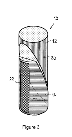
Figure 3 illustrates a first embodiment of a wedge stemming plug
according to the present invention;
Figure 4 illustrates a second embodiment of a wedge stemming plug
according to the present invention;
Figure 5 illustrates a third embodiment of a wedge stemming plug
according to the present invention;
Figure 6 is a cross-sectional view of a fourth embodiment of a wedge
stemming plug according to the present invention;
Figure 7 is a perspective view of the fourth embodiment of the wedge
stemming plug shown in Figure 6;
Figure 8 shows the wedge-shaped members of Figure 7 within a
partially cut-away elongate sleeve; and,
Figure 9 is a perspective view of a fifth embodiment of a wedge
stemming plug according to the present invention.
Detailed Description of Preferred Embodiments
A first embodiment of a stemming plug 10 in accordance with the invention,
for stemming a blast hole in a mine, is illustrated in Figure 3. The plug 10
comprises an active wedge-shaped member 12 having a sloping face
received in sliding relationship with a matching face of a passive wedge-
shaped member 14. In use, the active wedge-shaped member 12 is
positioned nearest to an explosive material in the blast hole, and the passive
wedge-shaped member 14 is positioned further from the explosive material in
the blast hole.
Figure 1 shows a cross section of a stope in a metalliferous underground
mine, with an upwardly extending, vertical blast hole 16. The stemming plug
10 is preferably located near the lower end of the blast hole 16, below
explosive material 18, for effectiveness in preventing the explosives from
CA 02922574 2016-02-26
WO 2015/035456
PCT/AU2014/000901
9
rifling out of the blast hole. Stemming contains the power of the explosive
blast to the location where it is needed (indicated by the arrows in Figure
1).
More effective use of wedging type arrangements for stemming and
otherwise blocking drill holes can be made by reducing the friction on the
active wedge-shaped member, increasing the friction on the passive wedge-
shaped member, or a combination of both.
In the stemming plug 10, the active wedge-shaped member 12 has a friction
reducing material provided on at least part of its surface to reduce the
sliding
resistance of the active wedge-shaped member 12 relative to the passive
wedge-shaped member 14. Preferably the active wedge-shaped member 10
is coated with a friction-reducing surface treatment 20. The friction-reducing
surface treatment may be PTFE paint, liquid or solid friction modifier.
In use, when a shock wave from initiation of the explosive material in the
blast hole encounters the active wedge-shaped member it acts as a piston,
sliding on the passive wedge-shaped member so that both wedge-shaped
members exert diametrically opposed forces against a wall of the blast hole
and are locked in place.
In this arrangement the passive wedge-shaped member 14 is further from the
explosive material 18, and the next to encounter the shockwave. The
passive wedge-shaped member 14 is preferably relatively stationary, or able
to offer greater resistance to movement, in comparison to the active wedge-
shaped member 12 for the pair to be effective. Increasing the resistance to
movement of the passive wedge-shaped member is achieved in
PCT/AU2013/000489 by backing that wedge up with a parcel of grout. The
grout increases the resistance to movement of the passive wedge-shaped
member through cohesion between the grout and the wall of the blast hole.
However there are other ways that the resistance to movement of the
passive wedge-shaped member can be increased. One is by applying a high
friction material, such as a surface coating (for example, a rubber coating),
to
the contact area between the passive wedge-shaped member and the wail of
CA 02922574 2016-02-26
WO 2015/035456
PCT/AU2014/000901
the hole. In Figure 3, the passive wedge-shaped member 14 has a high
friction material 22 applied to a surface thereof where the passive wedge-
shaped member 14 contacts the wall of the blast hole.
A further improvement in stemming effectiveness may be achieved by
5 increasing the mass of the passive wedge-shaped member relative to the
active wedge-shaped member, so that it offers greater resistance to
movement. It can be considered to have a greater stationary inertia. When
the combined wedges encounter the blasting force, the active wedge is
lighter and will therefore accelerate faster than the larger passive wedge. If
10 these circumstances prevail, the wedges will exert diametrically opposite
forces against the wall of the hole and lock in place, providing a maximum
amount of stemming resistance to the explosives.
Figure 4 shows a second embodiment of the stemming plug 30 where the
passive wedge-shaped member 34 is longer than the active wedge-shaped
member 32 so as to provide increased surface area in contact with the wall of
the blast hole. Lengthening the passive wedge-shaped member 34 has the
additional advantage of increasing the mass of the passive wedge-shaped
member. As with the previous embodiment, the active wedge-shaped
member 32 has a friction-reducing coating 20 on its surfaces. In this
embodiment, the passive wedge-shaped member 34 has greater resistance
to movement due to the greater surface area which is in contact with the wall
of the hole.
Also, in this instance, because the passive wedge-shaped member 34 has
greater mass, when the blasting force is applied to the combined wedge-
shaped members, the active wedge-shaped member 32, (with less mass),
will accelerate faster than the passive wedge-shaped member 34. In this
way the active wedge-shaped member 32 will apply a greater force to the
passive wedge-shaped member 34, and lock against the wall of the hole
harder, resisting the blasting forces to a greater extent.
It will be apparent that the maximum advantage is to be gained by:
= Reducing the friction on the active wedge;
CA 02922574 2016-02-26
WO 2015/035456 PCT/AU2014/000901
11
= Increasing the friction on the passive wedge; and,
= Having a heavier passive wedge-shaped member than active wedge-
shaped member.
Figure 5 shows a third embodiment of the stemming plug 40 which is similar
to the second embodiment 30, and therefore the same reference numerals
will be used to identify the like parts. As with the previous embodiment, the
passive wedge-shaped member 34 is of greater length, (and therefore has
greater mass) than the active wedge-shaped member 32. Furthermore the
active wedge-shaped member 32 has a friction-reducing surface treatment
20 applied to its surfaces. In this instance, the passive wedge-shaped
member 34 also has a high friction material 22 applied to a surface thereof
where the passive wedge-shaped member 34 contacts the wall of the blast
hole.
Because there is a difference in the relative frictional resistance of the
active
wedge-shaped member and passive wedge-shaped member, with the active
wedge-shaped member having the lower frictional resistance, under a
dynamic force the active wedge-shaped member pistons into the passive
wedge-shaped member further increasing the friction between the passive
wedge-shaped member and the wall of the hole.
This interaction compounds through the resistance being transferred from the
passive wedge to the active wedge. The greater the force applied to the
active wedge, causing displacement of the active wedge, the greater the
resistance provided by the passive wedge, as shown in Figure 2. This further
increases the frictional resistance between the passive wedge-shaped
member and the wall of the hole. This cycle continues until the shockwave
from the blast passes or the wedges fail under maximum load. In either
case, the wedges have provided the maximum amount of stemming to the
blast hole.
Figures 6 and 7 show a cross-sectional view and a perspective view
respectively of a fourth embodiment of the wedge stemming plug 50, which is
CA 02922574 2016-02-26
WO 2015/035456 PCT/AU2014/000901
12
similar to the first embodiment illustrated in Figure 3 and therefore the same
reference numerals will be used to identify the like parts. In this
embodiment,
the active wedge-shaped member 12 is enclosed within a friction-reducing
envelope, such as a plastic sleeve 52, in which the envelope provides a
lower coefficient of friction than the surface of the active wedge-shaped
member by itself. When the active wedge-shaped member 12 has the blast
force acting upon it, it is forced against the passive wedge-shaped member
14. The plastic sleeve 52 is long enough to allow for the sliding movement of
the active wedge-shaped member 12. The arrow in Figure 6 shows the
direction of movement.
Both the active and passive wedge-shaped members have a matching,
mating sliding surface at an acute angle to the direction of force from the
initiation of the explosive material. Ideally the wedge-shaped members are
cut from the same core material so that the sliding surface is identical on
each wedge. Preferably both of these faces are treated with a friction
reducing coating or arrangement, so that the sliding surfaces move freely. In
the event that the active wedge-shaped member is enveloped in a plastic
sleeve, this reduction in friction also applies to the passive wedge at this
sliding face even though it is not within the plastic sleeve.
Preferably the wedge stemming plug further comprises an outer liner 56, the
wedge-shaped members being received within the outer liner. The liner 56 is
similar to the elongate sleeve of porous material described in
PCT/AU2013/000489. The outer liner 56 preferably has a first inner join line
and a second outer join line, the inner join line being made of water-soluble
material and defining a first diameter of the liner which is smaller than a
second diameter defined by the second join line and is adapted to be
received in the blast hole.
Figure 8 shows the wedge-shaped members of Figure 7 within a partially cut-
away outer liner 56. Typically the liner 56 is made from a water-absorbent
material, with suitable friction properties to provide grip in the blast hole
during installation. Preferably the liner 56 is made from a lightweight,
CA 02922574 2016-02-26
WO 2015/035456 PCT/AU2014/000901
13
biodegradable material. Advantageously the liner 56 is made from hessian or
jute, which is a low cost, environmentally sustainable material.
The passive wedge-shaped member 14 is provided with a high friction
material 22 applied thereto, such as a rubber compound. Advantageously the
rubber compound 22 is applied so that is permeates the outer liner 56 along
the surface of the passive wedge-shaped member 14 where it contacts the
wall of the hole, so that the compound 22 contacts both the passive wedge-
shaped member 14 and the wall of the hole in use.
Preferably the wedge-shaped members are formed from a single cylindrical
elongate member cut through at an angle to form the pair of wedge-shaped
members, similar to the wedge-shaped members described in
PCT/AU2013/000489. Preferably each end of the cylindrical elongate
member is substantially flat, having a surface that is substantially
orthogonal
to a longitudinal axis of the cylindrical elongate member. Preferably the
cylindrical elongate member is cut through at an acute angle of between
about 55 and 85 . More preferably the cylindrical elongate member is cut
through at an acute angle of between about 75 and 85 .
Preferably the cylindrical elongate member forms a solid core of the plug.
Typically the solid core has an outer diameter about 10% less than the
nominal drill bit size to allow room for bit wear, and a further 3mm smaller
to
allow for a signal tube. Preferably the solid core is about 250mm to 600mm in
length. Typically the solid core of the plug is formed from cured grout
material. Preferably the solid core is a grout plug made of general purpose
(Portland) cement reinforced with fibres for additional strength and
toughness. Typically the reinforcing fibres are either one or a combination of
47mrn nnonofilannent poly fibres and 19mm monofilament fibres, of the kind
manufactured by Radmix and typically used in shotcrete applications.
A further possible configuration using the same philosophy is to have an
additional installation wedge at the base of the stemming plug. In this
configuration, a central passive wedge remains significantly longer and
heavier than either the active wedge or the installation wedge. Simple
CA 02922574 2016-02-26
WO 2015/035456
PCT/AU2014/000901
14
geometry and being made of the same materials means it as a minimum is
approximately twice the mass of the active wedge or the installation wedge.
Figure 9 illustrates a fifth embodiment of the wedge stemming plug 60, which
is similar to the previous embodiment illustrated in Figure 8 and therefore
the
same reference numerals will be used to identify the like parts and these will
not be described again in detail. The principal difference in this embodiment
is the addition of an installation wedge-shaped member 62 at the base of the
stemming plug 60. A central wedge-shaped member 64 is the passive
wedge-shaped member, and is approximately twice the mass of the active
wedge-shaped member 12. Instead of having a flat-faced base, as with the
previous passive wedge-shaped members 14 and 34, the central passive
wedge-shaped member 64 also has a wedge-shaped base.
The advantage of such a configuration is that it allows ease of installation,
whereby, in use, the installation wedge-shaped member 62 is forced against
the central passive wedge-shaped member 64 during installation. lt has the
advantage of being jolted against the passive wedge-shaped member 64,
typically of twice its own mass, allowing it to be more easily placed in
steeply
angled upholes. However the wedge stemming plug 60 can also be placed in
flat holes where gravity does not assist the locking of the wedges.
A further advantage is that the plug 60 is less likely to rattle loose in the
blast
hole if there is significant vibration from other holes being initiated around
it.
An even further advantage is that the active wedge-shaped member 12 in
this instance is not used to locate the plug, so it is freer to move in a
pistoning manner with the force of the initiating explosive material.
Additionally, if the wedge-shaped members are located relative to each other
as in Figure 9, on location in the blast hole the passive wedge-shaped
member 64 is already in a position to receive the active wedge-shaped
member 12 on initiation. That is, the central passive wedge-shaped member
64 is already forced against the wall of the blast hole and has frictional
resistance ready to receive the pistoning active wedge-shaped member 12.
CA 02922574 2016-02-26
WO 2015/035456
PCT/AU2014/000901
The angle of the sliding surfaces between the installation wedge-shaped
member 62 and the passive wedge-shaped member 64 need not be exactly
the same as that between the passive wedge-shaped member and the active
wedge-shaped member, but for all intents and purposes, it is similar.
5 Since the installation wedge-shaped member 62 is used primarily for
initially
locating the plug, it is required to grip the hole. In
this instance, the
installation wedge-shaped member 62 is free of friction-modifying materials
except for on the sliding surface which mates with the passive wedge-shaped
member 64. On this surface, and the matching surface on the passive
10 wedge-shaped member, friction-reducing materials would be advantageous.
In the instance of the plastic sleeve 52 being used in the plug 60, the
plastic
sleeve 52 would not encompass the installation wedge-shaped member 62,
but could go between the installation wedge-shaped member 62 and the
central passive wedge-shaped member 64, on the matching, sliding surface
15 (as shown in Figure 9).
Now that preferred embodiments of the wedge stemming plug and a method
of stemming a hole have with wedges have been described in detail, it will be
apparent that the described embodiments provide a number of advantages
over the prior art, including the following:
(i) The plugs are more effective than other uphole stemming products at
containing the forces produced upon detonation of the explosive
material.
(ii) They are cost effective being made of low cost materials.
(iii) They are very quick and easy to install.
(iv) No special installation tools are required.
(v) Modifying the frictional properties of the wedge-shaped members,
and providing a difference in mass between the wedge-shaped
members for different relative resistance characteristics, can
CA 02922574 2016-02-26
WO 2015/035456
PCT/AU2014/000901
16
improve the pistoning effect where the wedge nearest the blast is
forced into the adjacent wedge further from the blast.
(vi) The plug configuration also ensures the upper wedge-shaped
member transmits the larger proportion of the shockwave force into
resistance against the blast by the wedging action.
(vii) A further, significant advantage of this configuration is that the
wedge-shaped members can be made very economically and
simply from a previously cured grout plug.
It will be readily apparent to persons skilled in the relevant arts that
various
modifications and improvements may be made to the foregoing
embodiments, in addition to those already described, without departing from
the basic inventive concepts of the present invention. For example, whilst
hessian or jute has been described as the preferred material for making the
outer liner, the outer liner may be made from any suitable material.
Therefore, it will be appreciated that the scope of the invention is not
limited
to the specific embodiments described and is to be determined from the
appended claims.