Note: Descriptions are shown in the official language in which they were submitted.
CA 02922588 2016-02-26
,
=
Building module and method for utilizing thermal energy
[0001] The present invention relates to a building module, in
particular a facade
module, roof module or window module, for utilizing solar energy and/or for
thermal
insulation, having an inner pane and an outer pane, wherein an intermediate
space is
formed between the inner pane and the outer pane, a heat transfer element, in
particular
an absorber element, which is arranged in the intermediate space and has at
least one
functional surface for absorbing thermal radiation and/or for controlling the
temperature of
the intermediate space, and a fluid line in which a heat transport medium is
conducted,
wherein a thermal contact is formed between the heat transfer element and the
heat
transport medium in order to exchange heat between the heat transfer element
and the
heat transport medium.
[0002] The present invention further relates to a method for
producing a build-
ing module, in particular a facade module, roof module or window module, for
utilizing
solar energy and/or for thermal insulation, having the steps of: providing a
fluid line in
which a heat transport medium is conductable, providing a heat transfer
element, in
particular an absorber element, which has at least one functional surface for
absorbing
heat radiation and/or for controlling the temperature of ambient air, and
connecting an
inner pane and an outer pane to the fluid line such that an intermediate
space, in which
the heat transfer element is arranged, is formed between the inner pane and
the outer
pane.
[0003] Finally, the present invention relates to a heat
distribution arrangement
for a building having a plurality of building modules according to the present
invention and
a fluid system which, in order to exchange heat between the building modules,
connects
the fluid lines of the building modules at least thermally together.
[0004] Building modules of this type are usually fastened to
buildings and serve
to convert solar rays into thermal energy and/or electrical energy and to
utilize the thermal
and/or electrical energy obtained in this way in the building and/or to
thermally insulate the
building.
CA 02922588 2016-02-26
=
=
2
[0005] It is generally known from the prior art to arrange
solar collectors in win-
dows or in facade elements in order to convert the incident solar radiation
into thermal
energy. In this case, the solar collectors are usually in the form of elongate
slats in which
a fluid line is formed, a heat transport liquid flowing through said fluid
line in order to
transport away the heat which is produced in the solar collectors by the solar
rays and to
make it utilizable for heating for example a building interior. A window solar
collector of
this kind is known for example from DE 102 51 921 B4.
[0006] Alternatively, a building interior can also be heated by
means of solar
collector slats, as known from DE 28 30 745. In this case, the slats do not
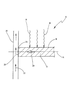
have a fluid line
in order to heat the building interior via a heat transport medium, but merely
have room air
of the building interior flowing around them in order to transport away the
heat that arises
in the slats as a result of the solar irradiation. In this case, the solar
collector slats are
arranged between two glass panes, wherein vents are formed in each case at the
lower
end of the glass panes and at the upper end of the glass panes in order to
allow cold air to
flow in between the glass panes and to allow warm air to flow out at the top
end.
[0007] Finally, it is known from DE 10 2008 047 327 B4 to form
solar collector
slats with a fluid system for heating a heat transport medium, with a
photovoltaic unit for
generating electrical energy, and with a further functional surface in order
for example to
reflect solar rays into the interior of a building.
[0008] A disadvantage with the solar collectors that are known
from the prior art
is that the collector slats are technically complicated and, on account of the
large diameter
brought about by the fluid line system, restrict the view through a window
equipped
therewith and at the same time greatly increase the thickness of the entire
window mod-
ule. Furthermore, it is a disadvantage that, in order to insulate the
particular building
interior, an additional insulating pane has to be provided or the intermediate
space in
which the collector slats are arranged has to be evacuated with a large
technical effort in
order to reduce the heat transmission through the pane, and the heat
transmission cannot
be set individually.
CA 02922588 2016-02-26
=
3
[0009] It is therefore the object of the present invention to
provide an improved
building module for utilizing solar energy, wherein the building module is
less technically
complicated and has heat transmission elements with a small overall size.
Furthermore, it
is the object of the invention to provide a building module with which the
heat transmission
through the building module can be set with low technical effort.
[0010] It is furthermore the object of the present invention to
provide a method
for producing such a building module.
[0011] This object is achieved in the case of the building
module mentioned at
the beginning in that the functional surface and the fluid line, to which the
thermal contact
is assigned, are arranged juxtaposed to one another when the functional
surface is
viewed in a perpendicular direction.
[0012] According to a second aspect, the abovementioned object
is achieved in
the case of the building module mentioned at the beginning in that the
intermediate space
is formed in a gastight manner and is filled with a gaseous medium so that
heat is ex-
changeable between the heat transport medium and the gaseous medium.
[0013] Finally, this object is achieved in the case of the
method mentioned at
the beginning in that a thermal contact is formed between the heat transfer
element and
the fluid line such that the functional surface and the fluid line are
arranged juxtaposed to
one another when the functional surface is viewed in a perpendicular
direction. According
to the invention, the expression "arranged juxtaposed to one another" is
understood as
meaning that the fluid line and the functional surface can be disposed
directly against one
another or can be arranged in a manner spaced apart from one another.
[0014] Since the functional surface of the heat transfer
element and the fluid
line to which the thermal contact is assigned are arranged juxtaposed to one
another, the
heat is exchanged in the lateral direction by means of heat conduction between
the
functional surface and the thermal contact, with the result that the heat
transfer element
can be formed without an integrated fluid line with a particularly small
diameter, can be
CA 02922588 2016-02-26
4
produced with low technical effort for example as an elongate metal element or
metal
plate and can be mounted with low technical effort. As a result, the technical
complexity of
the building module can be reduced overall and the installation space which is
necessary
for the heat transfer element can be reduced.
[0015] Since, according to the second aspect of the present invention,
the in-
termediate space is formed in a gastight manner and is filled with a gaseous
medium,
heat can be exchanged between the heat transport medium and the heat transfer
element
and between the functional surface and the gaseous medium such that the
gaseous
medium can be heated or cooled and the temperature of the gaseous medium can
be set
or adapted to an interior temperature, with the result that a flow of heat in
the inner pane
can be regulated. As a result, in particular the insulating action of the
building module can
be improved with low technical effort.
[0016] Therefore, the object of the present invention is fully achieved.
[0017] In a preferred embodiment, the heat transfer element is formed as
a
heat conductor for the thermal connection between the functional surface and
the thermal
contact.
[0018] As a result, the thermal connection between the functional
surface and
the thermal contact can be formed with low technical effort and can be
embodied in
particular with a small size.
[0019] It is furthermore preferred for the heat transfer element to be
formed of
an elongate element, wherein the thermal contact and the functional surface
are formed in
a manner offset with respect to one another in the axial direction of the heat
transfer
element.
[0020] As a result, in the embodiment as a window module, the view
through
the window module can be improved since the elongate elements do not cover the
entire
module area.
CA 02922588 2016-02-26
[0021] It is furthermore preferred for the thermal contact to be formed
on an end
section of the heat transfer element. In this case, it is particularly
preferred for the thermal
contact to be formed merely at the one end section of the heat transfer
element.
[0022] As a result, the heat transfer element can be mechanically
mounted at
the fluid line and at the same time form the thermal contact as heat transfer.
[0023] It is furthermore preferred for the thermal contact to be formed
at an end
face of the heat transfer element.
[0024] As a result, the thermal contact between the heat transfer
element and
the fluid line can be formed with simple means since the heat transfer element
has to be
fastened to the fluid line merely by way of its end face.
[0025] In a preferred embodiment, the heat transfer element has a free
end
section at which at least a part of the functional surface is formed.
[0026] As a result a view through the building module can be improved
since
the heat transfer element does not extend over the entire width of the
building module.
[0027] Alternatively, it is preferred for the heat transfer element to
have a ther-
mal contact at each of two opposite end sections, said thermal contacts each
being
assigned to a fluid line. In this case, it is particularly preferred for the
thermal contact to be
formed merely at the two end sections of the heat transfer element.
[0028] As a result, the transport of the thermal energy in the heat
transfer ele-
ment can be improved since two thermal contacts afford improved heat exchange
and two
thermal gradients arise in the heat transfer element.
[0029] It is furthermore preferred for the heat transfer element to be
fed through
the fluid line and to have a functional surface on each of the two sides of
the fluid line.
CA 02922588 2016-02-26
6
[0030] As a result, the technical effort for producing the heat transfer
elements
can be reduced since merely one heat transfer element has to be manufactured,
which
element projects out of the fluid line on both sides of the fluid line.
[0031] It is furthermore preferred for a plurality of heat transfer
elements which
are in contact with one another to be arranged in the intermediate space,
wherein longitu-
dinal axes of the heat transfer elements are arranged inclined to one another.
In other
words, the heat transfer elements form a kind of grid or mesh in order to
absorb the solar
radiation and emit it to the heat transport medium.
[0032] As a result, the heat exchange through the functional surface can
be im-
proved since the individual heat transport elements are in contact with one
another and
the functional surfaces are enlarged and distributed more regularly in the
building module.
[0033] It is furthermore preferred for the thermal contact to extend
into the fluid
line and to form convective heat transfer to the heat transport medium.
[0034] It is furthermore preferred for the heat transfer element to be
releasably
connectable to the fluid line in at least one axial end section.
[0035] As a result, the transport effort for the building module can be
reduced
considerably since the heat transfer elements can be transported in a
disassembled state.
[0036] It is furthermore preferred for the fluid line to have at least
one guide
strip extending in a longitudinal direction of the fluid line, the at least
one axial end section
of the heat transfer element being introducible into said guide strip.
[0037] As a result, the heat transfer element can be fixed to the fluid
line with lit-
tle assembly effort.
[0038] It is furthermore preferred for the axial end section to be
mounted so as
to be movable in the longitudinal direction of the fluid line.
CA 02922588 2016-02-26
7
[0039] As a result, a precise installation position of the heat transfer
element
can be set on site with little assembly effort.
[0040] It is furthermore preferred for the at least one axial end
section to be in-
troducible into the guide strip via an introduction opening in an axial end
section.
[0041] As a result, the heat transfer element can be plugged in easily
in the ax-
ial end section of the guide strip and be moved in the longitudinal direction
of the guide
strip into an end position, with the result that the assembly effort is
further reduced. As a
result, it is furthermore possible for a plurality of heat transfer elements
to be introduced
into the guide rail in the same way, with the result that the assembly effort
for the heat
transfer elements is further reduced.
[0042] It is furthermore preferred for a plurality of heat transfer
elements to be
mounted in the guide strip and to be spaced apart by means of spacer elements
which are
mounted in the guide strip.
[0043] As a result, the assembly effort and the technical effort for
exact posi-
tioning of the heat transfer elements in the guide rail is further reduced
since the heat
transfer elements and the spacer elements have to be plugged into the guide
strip from
the axial end section merely in an alternate manner.
[0044] As a result, the heat transfer between the absorber element and
the heat
transport medium can be improved since an area of the thermal contact around
which the
heat transport medium flows is increased.
[0045] It is furthermore preferred for the inner pane and the outer pane
to be
connected together by means of a connecting element which forms a frame of the
building
module, wherein the fluid line is integrated into the frame at least on one
side of the solar
energy module.
CA 02922588 2016-02-26
8
[0046] As a result, a particularly compact structural form of the
building module
can be achieved, wherein the fluid line is integrated in the frame so as not
to be visible
from the outside.
[0047] It is furthermore preferred for the outer pane to be formed from
a materi-
al that is transparent to visible light and for the surface of the inner pane
which faces the
intermediate space to have an infrared reflection layer in order to reflect
the incoming
infrared rays into the intermediate space.
[0048] As a result, the efficiency of infrared absorption can be
increased since
infrared radiation which is not absorbed by the functional surface or does not
strike the
functional surface when the solar rays are incident is reflected by the
infrared reflection
layer and can be absorbed for example by a rear side of the heat transfer
elements. As a
result, an efficiency-increasing heat accumulation can be formed in the
intermediate
space.
[0049] In a preferred embodiment, an infrared reflection layer is
arranged on a
surface of the outer pane which faces the intermediate space in order to
reflect infrared
rays into the intermediate space.
[0050] As a result, infrared rays which are reflected out of the
intermediate
space or by the surface of the inner pane can be reflected back into the
intermediate
space, with the result that the efficiency of infrared absorption can be
increased.
[0051] It is furthermore preferred for the fluid line to be assigned a
heat accu-
mulator in order to take up and store heat from the heat transport medium and
to emit
stored heat to the heat transport medium. Alternatively or in combination with
the heat
accumulator, a heat pump can be provided in order to utilize the thermal
energy and to
convert it for example into electrical energy.
[0052] As a result, thermal energy can be stored during solar
irradiation and, at
a later time when solar irradiation is reduced on account of the weather or
time of day, the
CA 02922588 2016-02-26
9
heat is returned to the heat transport medium in order to utilize the thermal
energy in a
demand-oriented manner.
[0053] It is furthermore preferred for the fluid line to be connected to
a heat
pump in order to dissipate heat from the heat transport medium and/or supply
heat to the
transport medium.
[0054] As a result, it is also possible to dissipate small quantities of
heat from
the heat transport medium or for the heat transport medium to be heated by
small quanti-
ties of heat.
[0055] It is furthermore preferred for a cross-sectional area of the
heat transfer
element to have a smaller diameter than a cross-sectional area of the fluid
line.
[0056] It is furthermore preferred for the heat transfer element to have
an elon-
gate module body with a polygonal cross section on which a plurality of
functional surfac-
es are formed.
[0057] As a result, for example different functional surfaces can be
utilized in a
demand-oriented manner for different functions. In particular, the different
functional
surfaces can be oriented in this case in a demand-oriented manner in order to
utilize the
incident solar rays differently.
[0058] It is particularly preferred in this case for a photovoltaic unit
to be ar-
ranged on at least one of the functional surfaces.
[0059] As a result, the incident solar rays can be converted into
electrical ener-
gy and thus the efficiency of the building module can be enhanced.
[0060] It is furthermore preferred in this case for at least one of the
functional
surfaces to have a reflective surface.
CA 02922588 2016-02-26
[0061] As a result, the incident solar rays can be deflected into an
interior of a
building or be reflected outward by the solar energy module in order either to
accordingly
illuminate the interior of the building or to reduce the solar irradiation.
[0062] It is generally preferred for the heat transfer element to be
configured as
a solid body. In this case, the expression "solid body" should be understood
as meaning
that no cavities are formed in the heat transfer element.
[0063] As a result, the heat transfer by heat conduction within the heat
transfer
element can be improved and thus the exchange of heat between the functional
surface
and the heat transport medium can be increased.
[0064] In the method according to the invention, it is particularly
preferred for an
axial end of the heat transfer element to be connected to a guide rail of the
guide strip.
[0065] As a result, the assembly effort and the effort for positioning
the heat
transfer elements can be reduced.
[0066] It is furthermore preferred for the axial end of the heat
transfer element
to be introduced into the guide strip at an axial end of the guide strip.
[0067] As a result, the heat transfer element can be assembled on the
axial end
section of the guide strip by simply being plugged in, without further holding
mechanisms
needing to be provided.
[0068] It is furthermore preferred for a plurality of heat transfer
elements and a
plurality of spacer elements to be introduced alternately into the guide strip
in order to
space apart the heat transfer elements in an installed state.
[0069] As a result, the assembly effort and the positioning effort for
the heat
transfer elements can be further reduced since the heat transfer elements and
the spacer
CA 02922588 2016-02-26
11
elements merely have to be plugged alternately into the introduction opening
in the guide
strip.
[0070] By way of the present invention, a building module having a heat
trans-
fer element which is arranged between the inner pane and the outer pane can be
provided
overall in a compact structural form, with the result that overall the
production effort is
reduced and at the same time the view through the building module is improved.
This is
achieved according to the invention in that the heat transfer element merely
exchanges
heat between the functional surface and the thermal contact arranged on an end
section
of the heat transfer element by means of heat conduction and thus the heat
transfer
element merely has to be formed from a stable and thermally conductive
material. The
fluid line in which the heat transport medium is conducted is in this case
formed separate-
ly from the functional surface and is connected to the end section or to two
opposite axial
end sections of the heat transfer element merely via the thermal contact. As a
result, it is
possible to omit a complicated fluid line in the heat transfer element, with
the result that
the heat transfer element is less technically complicated and at the same time
can be
manufactured in a compact structural form. In an alternative embodiment or in
a particular
embodiment, the thermal contact and the functional surface are arranged
juxtaposed to
one another when the functional surface is viewed in a perpendicular
direction. In other
words, the thermal contact and the functional surface do not overlap when the
functional
surface is viewed in a perpendicular direction.
[0071] Furthermore, according to the second aspect of the present
invention, a
flow of heat through the solar energy module can be reduced when heat is
transferred
from the heat transport medium to the functional surface and from the
functional surface
to the gaseous medium in order to set a temperature of the gaseous medium in
the
intermediate space. As a result, the flow of heat through the inner pane can
be regulated,
with the result that in particular the insulation action of the entire
building module can be
improved.
[0072] It goes without saying that the features and properties of the
building
module according to the invention also apply or are applicable in a
corresponding manner
to the method according to the invention for producing the building module.
CA 02922588 2016-02-26
12
[0073] It goes without saying that the abovementioned features and those
yet to
be explained below are usable not only in the combination given in each case
but also in
other combinations or on their own without departing from the scope of the
present
invention.
[0074] Exemplary embodiments of the invention are illustrated in the
drawing
and explained in more detail in the following description. In the drawing:
Fig. 1 shows a schematic partial view of a building module for utilizing
solar
energy;
Fig. 2 shows a schematic sectional side view of the building module from
fig. 1;
Fig. 3 shows a schematic sectional side view of a building module for
regulat-
ing the flow of heat;
Fig. 4 shows a schematic view of the building module and of an
associated flu-
id system for explaining the operation of the building module;
Fig. 5a shows a schematic view of an embodiment of the heat transfer elements
having a free axial end;
Fig. 5b shows a schematic view of an embodiment of the heat transfer elements
having two-sided thermal contact;
Fig. 6 shows a schematic partial view of the building module for
explaining an
embodiment of the thermal contact between the heat transfer element
and heat transport medium;
Fig. 7 shows a schematic partial view for explaining an alternative
embodiment
of the thermal contact between the heat transfer elements and the heat
transport medium;
CA 02922588 2016-02-26
13
Fig. 8a shows a schematic partial view of the building module having heat
trans-
fer elements which have a free axial end;
Fig. 8b shows a schematic side view of the building module from fig. 8a;
Fig. 9 shows a schematic sectional side view of the building module
having
heat transfer elements which have a plurality of functional surfaces and
a polygonal cross-sectional area;
Figs 10a, b
show schematic sectional views of fluid lines having (a) guide strip(s) for
connecting the heat transfer elements; and
Fig. 11 shows a schematic side view for explaining the mounting of the
heat
transfer elements by means of spacer elements.
[0075] Fig. 1 illustrates a schematic partial view of a building module
which has
the overall designation 10. The building module 10 has an inner pane (not
illustrated here)
and an outer pane (not illustrated here) arranged parallel thereto, said outer
pane extend-
ing parallel to the plane of the drawing in fig. 1 and being explained in more
detail in the
following text. Such building modules 10 serve to clad a building, for example
as a facade
module, roof module or window module and can be in the form of a solar energy
module
and/or of an insulation module 10.
[0076] The building module 10 has a heat transfer element 12, or an
absorber
element 12, which is in the form of an elongate element and has a longitudinal
axis 14. On
an outer surface, the absorber element 12 has a functional surface 16 which is
configured
to absorb solar rays 18. The functional surface 16 is in thermal contact with
the absorber
element 12 so that the solar rays 18 absorbed by the functional surface 16
heat the
absorber element 12.
CA 02922588 2016-02-26
14
[0077] The building module 10 furthermore has a fluid line 20 in which a
heat
transport medium 22 is conducted. The fluid line 20 and the functional surface
16 are
arranged juxtaposed to one another when the functional surface 16 is seen in a
perpen-
dicular direction, or in a perpendicular projection of the functional surface
16.
[0078] The absorber element 12 is in thermal contact with the heat
transport
medium 22 at an axial end 24 by means of a thermal contact 26, in order to
exchange
heat between the absorber element 12 and the heat transport medium 22. In this
case,
the section of the fluid line 20 on which the thermal contact 26 is formed is
arranged
juxtaposed to the functional surface 16 when the functional surface 16 is
viewed in a
perpendicular direction. Furthermore, the absorber element 12 is mounted on
the fluid line
20 at the axial end 24.
[0079] The absorber element 12 is in the form of a heat conductor such
that
heat, which is generated in the functional surface 16 or in the absorber
element 12 by the
incident solar radiation, is transported by heat conduction to the thermal
contact 26 and is
emitted via convection to the heat transport medium 22 by means of the thermal
contact
26. Since the thermal contact 26 is formed at the axial end 24 of the absorber
element 12
and the functional surface 16 is formed along the length of the absorber
element 12, a
flow of heat 28 is produced by heat conduction in the absorber element 12,
said flow of
heat running in the axial direction of the absorber element 12 or parallel to
the longitudinal
axis 14.
[0080] In other words, the thermal contact 26 and the functional surface
16 are
arranged juxtaposed to one another or in a manner offset with respect to one
another in
the axial direction of the absorber element 12, or the functional surface 16
and the fluid
line 20 are arranged partially or completely juxtaposed to one another or in a
manner
offset with respect to one another when the functional surface 16 is viewed in
a perpen-
dicular direction. Put another way, the thermal contact 26 is formed merely on
a lateral
end section when the functional surface 16 is viewed in a perpendicular
direction.
CA 02922588 2016-02-26
[0081] The absorber element 12 is preferably in the form of a solid
body, i.e. the
absorber element 12 preferably does not have any cavities, in order to allow
heat conduc-
tion that is as good as possible in the axial direction. The absorber element
12 is formed
from a material with good heat conductivity, for example from a metal such as
copper or
aluminum. The heat transport medium 22 is guided past the thermal contact 26
orthogo-
nally to the longitudinal axis 14 in order to allow heat exchange between the
heat
transport medium 22 and the thermal contact 26.
[0082] Since heat transport takes place between the functional surface
16 and
the thermal contact 26 by heat conduction, the absorber element 12 can be
manufactured
in a particularly compact structural form and with little technical effort and
be arranged
between the inner pane and the outer pane of a window so that the view through
the
panes is impaired only a little. The heat transport medium 22 heated in this
way can be
utilized for example to heat an interior of a building, or the heat can be
stored in order to
heat the absorber element 12 in the event of relatively low solar irradiation
18, as is
explained in more detail below.
[0083] The heat transfer element 12, or the absorber element 12, can
have any
desired form, in particular a round, square or rectangular base area. As an
alternative to
the elongate form described here, the heat transfer element 12 can also be in
the form of
a plate which is in contact with the fluid line 20 at a lateral edge by means
of the thermal
contact 26 and at the same time is mechanically mounted on the fluid line 20.
In this case,
the fluid line 20 and the functional surface 16 are arranged juxtaposed to one
another or in
a manner laterally offset with respect to one another in a perpendicular
projection of the
functional surface 16.
[0084] In a preferred embodiment, the functional surface 16 is blackened
or an-
odized in order to improve the heat transfer to the functional surface 16.
[0085] Fig. 2 shows the building module 10 from fig. 1 in a schematic
sectional
side view. Identical elements are designated by the same reference numerals,
with only
particular features being explained here.
=
CA 02922588 2016-02-26
16
[0086] The building module 10 has an inner pane 30 and an outer pane 32,
which are arranged parallel to one another and are connected together by means
of
connecting elements 34. Formed between the inner pane 30 and the outer pane 32
is an
intermediate space 36, in which the absorber elements 12 are arranged.
[0087] The longitudinal axes 14 of the absorber elements 12 extend
substan-
tially parallel to the inner pane 30 and the outer pane 32 and perpendicular
to the plane of
the drawing in the illustration in fig. 2.
[0088] The inner pane 30 is in the form of an insulating glass pane and
has two
separate panes 38, 40 which are separated from one another by a vacuum 42 or a
gas
filling. Alternatively, the pane 30 can also be in the form of a single pane.
[0089] Arranged on a surface 46, facing the intermediate space 36, of
the inner
pane 30 is an infrared reflection layer 48 in order to reflect infrared
radiation or other
wavelengths of the incident solar rays 18 into the intermediate space 36 or
onto the
functional surfaces 16 of the absorber elements 12. Arranged on a surface 47,
facing the
intermediate space 36, of the outer pane 32 is an infrared reflection layer 49
in order to
reflect reflected infrared radiation or other wavelengths into the
intermediate space 36.
The reflection layers 48, 49 are configured so as to be transparent for
visible light.
[0090] The outer pane 32 is formed in a transparent manner in order to
transmit
the solar rays 18 into the intermediate space 36 such that the solar rays 18
striking the
functional surface 16 can heat the absorber elements 12. Infrared radiation of
the solar
rays 18 which strike the inner pane 30 through the intermediate space 36 are
reflected by
the infrared reflection layer 48 and reflected at least partially onto the
functional surfaces
16 of the absorber elements 12. The infrared rays reflected in this way can be
reflected by
the second infrared reflection layer 49 in the intermediate space 36 in order
in this way to
generate a heat accumulation. As a result, the efficiency of the utilization
of the incident
solar rays 18 can be increased.
CA 02922588 2016-02-26
17
[0091] The building module 10 is preferably arranged on buildings and
serves
as a facade module, roof module or window module in order to accordingly
utilize the
incident solar energy. In this case, the inner pane 30 faces an outer wall of
the building or
an interior of the building and the outer pane 32 faces a surrounding area of
the building.
It is possible for the inner pane 30 to be formed in a nontransparent manner
when used as
a facade module or to be formed in a transparent manner when used as a window
mod-
ule.
[0092] Fig. 3 shows a schematic sectional side view of the building
module 10.
Identical elements are designated by identical reference numerals, with only
particular
features being explained here.
[0093] In the function illustrated in fig. 3, the building module 10
serves for insu-
lating an interior or the building generally from an external area, wherein
the interior or in
the internal area has an internal temperature TI and the external area has an
external
temperature TA. In the situation illustrated here, the external temperature TA
is lower than
the internal temperature TI and so, under normal circumstances, for example
when a
normal insulating glass pane or normal insulation is used, a flow of heat from
inside to
outside would form.
[0094] In the embodiment illustrated here, the intermediate space 36 is
closed
off in a gastight manner by the inner pane 30, the outer pane 32 and the
connecting
elements 34, and filled with a gaseous medium, for example an inert gas such
as argon.
In the situation illustrated in fig. 3, thermal energy is transferred from the
heat transport
medium 22 via the thermal contact 26 to the heat transfer elements 12, such
that heat is
emitted to the gaseous medium via the functional surfaces 16, as is indicated
by arrows
50. As a result, an intermediate-space temperature TZ of the gaseous medium in
the
intermediate space 36 is increased and adapted to the internal temperature TI.
As a
result, a temperature gradient between the internal area and the intermediate
space 36
can be reduced, such that an inner heat flow 52 that arises on account of the
temperature
gradient through the inner pane 30 is reduced. Furthermore, an outer heat flow
54 through
the outer pane 32 arises in accordance with the temperature gradient between
the inter-
mediate-space temperature TZ and the external temperature TA. As a result of
the
CA 02922588 2016-02-26
18
intermediate-space temperature TZ being adapted or raised to the internal
temperature TI,
the inner heat flow 52 can be reduced very greatly, with the result that the
heat loss from
the interior can be reduced very greatly, or the interior can be insulated
very well from the
external area.
[0095] In this process, thermal energy that was generated by the solar
rays 18
and was buffer-stored for example in a heat accumulator is preferably used in
the heat
transport medium 22. As a result, solar energy can be used and buffer-stored
and utilized
for insulating the interior from the external area. In one particular
embodiment, the heat
transport medium 22 can also be heated by an additional energy source in order
to
accordingly raise the intermediate-space temperature TZ and thus to achieve
improved
insulation of the interior from the external area.
[0096] In a similar manner, the gaseous medium can also be cooled by the
heat
transfer elements 12, or heat can be transferred from the gaseous medium to
the heat
transport medium 22 by the heat transfer elements 12 in order to cool the
gaseous
medium and thus the intermediate space 36. As a result, the inner heat flow 52
can be
increased, with the result that the internal temperature TI can be reduced and
thus the
interior can be cooled or air-conditioned. In this process, the heat transport
medium 22
can be cooled for example by a cooling system.
[0097] Fig. 4 schematically illustrates the building module 10 with a
fluid sys-
tem. Identical elements are designated by identical reference numerals, with
only the
particular features being explained here.
[0098] The building module 10 has three of the heat transfer elements
12,
which are arranged between the inner pane 30 and the outer pane 32 and extend
over the
entire width of the building module 10. The building module 10 forms a
building window in
the embodiment illustrated in fig. 4.
[0099] The building module 10 has a frame 60 which mounts the inner pane
30
and the outer pane 32. Arranged in the frame 60 is the fluid line 20, in which
the heat
CA 02922588 2016-02-26
19
transport medium 22 is conducted, said heat transport medium 22 being in
thermal
contact with the three heat transfer elements 12. The heat transport medium 22
is ther-
mally connected to in each case one of the heat transfer elements 12 in each
case by one
of the thermal contacts 26. The fluid line 20 is thermally separated from the
panes 30, 32
by means of a spacer, in order to improve thermal insulation and to reduce
mechanical
stresses.
[00100] The fluid line 20 is part of a fluid system which has the overall
designa-
tion 62 in fig. 4. The fluid system 62 has a fluid circuit and a heat
exchanger 64 in order to
circulate the heat transport medium 22 and accordingly dissipate heat from the
heat
transfer elements 12 or supply heat to the heat transfer elements 12. The heat
exchanger
64 exchanges heat with a thermal system (not illustrated here), for example an
interior
heating system for heating the interior of the building, a heat accumulator
for storing the
thermal energy absorbed by the heat transfer elements 12, or a heat pump for
dissipating
or supplying thermal energy. The heat exchanger 64 has a pump (not illustrated
in more
detail here), in order to pump the heat transport medium 22 around in the
fluid system 62.
The heat exchange between the heat exchanger 64 and the heat transfer elements
12
preferably takes place in this case via setting of a mass flow of the heat
transport medium
22 in the fluid line 20. Arranged in the intermediate space 36 is a
temperature sensor, and
on the basis of the intermediate-space temperature TZ measured in this way,
the mass
flow or the pump output is set.
[00101] In this way, thermal energy can be dissipated from the heat transfer
el-
ements 12 using simple means in order to accordingly utilize the thermal
energy, or
thermal energy can be supplied to the heat transfer elements 12 in order to
heat the
intermediate space 36 and thus to reduce the inner heat flow 52, or the
intermediate
space 36 can be cooled by removal of heat. In a particular embodiment, the
thermal
energy can also be utilized to cool the interiors, for example by means of a
heat pump.
[00102] In one particular embodiment, a number of the housing modules 10 are
connected via the fluid system 62 and/or the heat exchanger in order to
exchange thermal
energy between the building modules 10. In this case, for example solar energy
can be
transferred from building modules 10 that are irradiated to modules 10 that
are not irradi-
CA 02922588 2016-02-26
ated, for example modules 10 facing away from the sun, in order to reduce the
inner heat
flow 52 there and to insulate the building.
[00103] In fig. 4, the fluid line 20 is formed on one side in the frame 60. It
goes
without saying that the fluid line 20 can also be formed on a number of or all
sides of the
frame 60. Furthermore, different fluid lines 20 which are assigned to
different fluid systems
62 can be formed in the frame 60.
[00104] Fig. 5a schematically illustrates an embodiment of the heat transfer
ele-
ments 12, or of the absorber elements 12. In this case, the heat transfer
elements 12 each
have the axial end 24 on which the thermal contact 26 is formed, in order to
exchange
heat between the heat transfer elements 12 and the heat transport medium 22.
The heat
transfer elements 12 furthermore each have a free end 66 which is opposite the
axial end
24. As a result, solar energy can be absorbed by the functional surface 16 or
heat can be
emitted from the functional surface 16 to the intermediate space 36, wherein
at the same
time a central section of a window formed in such a way remains free, thereby
allowing an
improved view through the window. The thermal contact 26 is formed merely at
the axial
end 24. Thus, in the heat transfer element 12 in fig. 5a, the heat transport
28 is formed by
heat conduction merely in an axial direction.
[00105] Fig. 5b illustrates an alternative embodiment of the heat transfer ele-
ments 12, or of the absorber elements 12. In this case, the heat transfer
elements have
the thermal contact 26 at the axial end 24 for exchanging heat energy with the
heat
transport medium 22. Furthermore, the heat transfer elements 12 each have a
further
thermal contact 70 at the end 68 opposite the axial end 24, said further
thermal contact 70
preferably being identical to the thermal contact 26. The thermal contact 70
is assigned to
a further fluid line 72, which can be connected to the first fluid line 20.
[00106] The thermal contacts 26, 70 are formed merely at the axial ends 24,
68.
As a result, in each case two heat flows 28 are formed by heat conduction in
the heat
transfer elements 12, said heat flows 28 being oriented in opposite directions
toward the
thermal contacts 26, 70.
CA 02922588 2016-02-26
21
[00107] In a section between the thermal contacts 26, 70, the heat transfer
ele-
ments 12 can have a compensation element for compensating for thermal
expansion.
[00108] In a particular embodiment, the thermal contact 26 is formed on an
axial
section of the heat transfer element 12, said axial section being formed in
the axial
direction between two functional surfaces 16.
[00109] Fig. 6 illustrates a schematic partial view of a building module 10
having
the frame 60 in order to explain the thermal contact 26. In the embodiment
illustrated in
fig. 6, the heat transfer elements 12 project into the fluid line 20 such that
an enlarged
surface area is formed as the thermal contact 26. As a result, the heat
transfer between
the heat transfer element 12 and the heat transport medium 22 can be improved.
[00110] In this embodiment, the thermal contacts 26 can be formed with a
ribbed
structure in order to enlarge a surface area of the thermal contact 26 and
thereby to
improve the heat transfer.
[00111] Fig. 7 schematically illustrates an alternative embodiment of the
thermal
contact 26.
[00112] The heat transfer elements 12 are in this case connected externally to
the fluid line 20 so that the heat is transferred from the heat transfer
element 12 to the
fluid line 20 and from the fluid line 20 to the heat transport medium 22. In
this case, the
outer wall of the fluid line 20 and a contact surface between the heat
transfer element 12
and the fluid line 20 forms the thermal contact 26. The advantage of this
embodiment of
the thermal contact 26 is that the fluid line 20 can be sealed off with less
technical effort
and the contact can be made with the absorber elements 12 with little effort.
For example,
the heat transfer elements 12 can be welded to the fluid line 20 in this
embodiment.
[00113] In one particular embodiment, the fluid line 20 can have indentations
into
which the end sections 24 of the heat transfer elements 12 are introduced and
form the
CA 02922588 2016-02-26
22
thermal contact 26 with the fluid line 20. As a result, it is possible to omit
complicated
sealing of the fluid line 20.
[00114] In one particular embodiment, the thermal contact 26 is formed in an
elastic manner, for example by a thermal paste or a resilient contact in order
to compen-
sate the thermal expansion of the heat transfer elements 12. In a further
embodiment, the
fluid lines 20 are mounted in a movable manner in order to compensate the
thermal
expansion of the heat transfer elements 12.
[00115] Fig. 8a illustrates a schematic partial view of the building module 10
hav-
ing heat transfer elements 12, or absorber elements 12, from the embodiment in
fig. 5a. In
this case, the heat transfer elements 12 are in thermal contact with the fluid
line 20 by
means of the respective end 24. The respective free end 66 projects into the
intermediate
space 36 such that an internal area 74 of the solar energy module 10 remains
free and
allows a slightly restricted view through the panes 30, 32.
[00116] In this embodiment, the heat transfer elements 12 are formed both on a
vertical side of the frame 60 and on a horizontal side of the frame 60. As a
result, the
efficiency of the building module 10 can be increased.
[00117] In a further embodiment, the absorber elements 12 can also be arranged
inclined or obliquely with respect to one another and be connected together
such that a
grid or a mesh of heat transfer elements 12 is formed.
[00118] Fig. 8b illustrates a side view of the frame 60 of the building module
10
from fig. 8a. Identical elements are designated by identical reference
numerals, with
merely the particular features being explained here.
[00119] The base area of the heat transfer elements 12, or of the absorber ele-
ments 12, is formed in an elongate or rectangular manner in this embodiment,
such that
the heat transfer elements 12 are in the form of horizontally arranged plates.
Alternatively,
CA 02922588 2016-02-26
23
these plate-like heat transfer elements 12 can also be arranged
perpendicularly or parallel
to a longitudinal axis of the respective frame element or the associated fluid
line 20.
[00120] Fig. 9 illustrates a particular embodiment of the building module 10
hav-
ing absorber elements 12 which have a polygonal cross section. In this case,
the cross
section has a planar functional surface 76 and two curved functional surfaces
78, 80. The
absorber elements 12 can in this case be mounted so as to be rotatable about
the longi-
tudinal axis 14 and can accordingly be oriented with respect to the solar rays
18. In this
case, the straight functional surface 76 can be oriented such that the solar
rays 18 strike
the straight functional surface 76 orthogonally. In a preferred embodiment, a
photovoltaic
unit is arranged on the straight functional surface 76 in order to generate
electrical energy
by way of the incident solar radiation 18. The functional surfaces 78, 80 are
formed so as
to reflect and/or to absorb the incident solar rays 18, in order to illuminate
the interior
and/or to heat the heat transport medium 22. In a simplified variant, the
absorber ele-
ments 12 can also be mounted in a fixed manner.
[00121] The functional surface 78 is in this case formed in a concave manner
and the functional surface 80 is formed in a convex manner.
[00122] Figs 10a and b each illustrate schematic sectional illustrations of
embod-
iments of the fluid line 20 and the heat transfer elements 12. Identical
elements are
designated by identical reference numerals, with merely the particular
features being
explained here.
[00123] The fluid line 20 in fig. 10a has a guide strip 82 which extends in a
longi-
tudinal direction of the fluid line 20 on the outer side of the fluid line 20.
The guide strip 82
has two opposite L-shaped guide sections. The guide strip 82 is configured to
receive a
connecting section 84, which is formed at the axial end 24 of the heat
transfer element 12,
and to accordingly mount and fix the heat transfer element 12 in a lateral
direction trans-
versely to the longitudinal direction of the fluid line 20. In the embodiment
illustrated here,
the guide section 84 has lateral protrusions 86 which engage behind the L-
shaped guide
sections or guide grooves of the guide strip 82 in order to mount the heat
transfer element
CA 02922588 2016-02-26
24
12. In an alternative embodiment, the axial end 24 does not have lateral
protrusions 86
and is formed in a substantially rectilinear manner, wherein, for axial
guidance, the fluid
line 20 serves as an axial stop.
[00124] Formed at an axial end of the fluid line 20, or of the guide strip 82,
is an
insertion opening into which the guide section 84 of the axial end 24 of the
heat transfer
element 12 is introduced into the guide strip 82 and is then moved in the
axial direction in
the guide strip 82 in order to assemble the heat transfer element 12.
[00125] Only one axial end 24 of the heat transfer element 10 is illustrated
in fig.
10a, for example for heat transfer elements 12 having an opposite free end 66.
It goes
without saying that the guide strip 82 and the guide section 84 can also be
formed at
opposite ends of the heat transfer element 12 in order to mount the heat
transfer element
12 on both sides.
[00126] Fig. 10b schematically illustrates an alternative embodiment of the
fluid
line 20 having guide strips 82 on both sides. Identical elements are
designated by identi-
cal reference numerals, with merely the particular features being explained
here.
[00127] On opposite sides, the fluid line 20 has in each case one of the guide
strips 82 in which two connecting sections 84 of two heat transfer elements 12
can
accordingly engage in order to accordingly mount the heat transfer elements
12.
[00128] During assembly, the heat transfer elements 12 are accordingly guided
through the introduction opening into the guide strip 82 and are spaced apart
from one
another by means of a spacer element, which is likewise introduced into the
guide strip
82, and accordingly supported with respect to one another. As a result, the
heat transfer
elements 12 can be mounted in a fixed position and can be assembled with low
technical
effort. The thermal contact 26 is then formed by a separate thermal contact
element 88 or
by a thermally conductive paste 88.
CA 02922588 2016-02-26
[00129] Fig. 11 illustrates a schematic side view of the guide strip 82.
Identical
elements are designated by identical reference numerals, with merely the
particular
features being explained here.
[00130] The heat transfer elements 12 and spacer elements 90 are introduced
alternately into the guide strip 82, as is indicated by arrows 92, in order to
accordingly
space apart the heat transfer elements 12 and to support them with respect to
one
another. The spacer elements 90 in this case accordingly have an outer shape
that is
complementary to the heat transfer elements 12, such that the heat transfer
elements 12
can accordingly be mounted in a play-free and fixed manner. As a result of the
inherent
weight of the heat transfer elements 12, the heat transfer elements 12 and the
spacer
elements 90 are pressed against one another, with the result that the thermal
contact
between the heat transfer elements 12 and the spacer elements 90 is improved.
[00131] As a result, simple assembly of the heat transfer elements 12 is
possible
by simple alternate plugging in of the heat transfer elements and spacer
elements 90. In
one particular embodiment, the heat transfer elements 12 and the spacer
elements 90 are
connected thermally together for example by means of a thermal conductive
paste 88 and
the spacer elements 90 are furthermore connected thermally to the fluid line
20 such that
the heat transfer between the heat transfer element 12 and the fluid 22 in the
fluid line 20
is improved.