Note: Descriptions are shown in the official language in which they were submitted.
CA 02922635 2016-02-26
WO 2014/035365 PCT/US2012/052492
SYSTEM AND METHOD FOR PLASMA GENERATION
FIELD OF THE INVENTION
[0001] Embodiments of the present invention relate to the field of plasma
generation and, in
particular, to the generation of plasma contained within a boundary without a
container.
BACKGROUND INFORMATION
[0002] Plasmas have long been the subject of research and investigation and
continue to be
the focus of many academic and industrial studies. However, while plasma is
understood to be
the most common form of matter in the universe, its use as a technology with
widespread
industrial applicability has been limited.
[0003] The use of plasmas in industry has traditionally been limited by
various practical
considerations. Plasmas are generally accompanied by thermal pressure
gradients. Because many
plasmas operate with high energy, the air comprising the plasma becomes hot
and expands.
Thus, any increase in plasma energy is typically accompanied by an increase in
plasma volume.
Plasmas with energies that have been useful in industry typically have had
volumes so large that
they are cumbersome.
[0004] In addition, plasmas typically generate strong electromagnetic and
RF interference,
making plasma-based devices largely incompatible with other electronic
devices. Without the
ability to control the interference generated by a plasma-based device, the
operation of many
electronic devices in the vicinity of the plasma-based device becomes
needlessly compromised.
[0005] Plasmas have also typically required great amounts of power for
their operation.
Because of the high energies typically associated with plasma use, large power
supplies have
traditionally been required to operate plasmas, making plasmas unavailable in
portable or mobile
applications and available only for applications with the resources to
generate the requisite
power.
[0006] Also, plasmas developed for industrial use have typically not
generated enough
physical force to be effective in stopping a projectile. Because most
industrially developed
plasmas have random force vectors associated with them, the use of plasma as
physical shielding
has been unavailable.
1
CA 02922635 2016-02-26
WO 2014/035365 PCT/US2012/052492
SUMMARY OF THE INVENTION
[0007] According to an embodiment of the present invention, a system for
generating a
plasma may include a first electrode; a second electrode disposed adjacent the
first electrode; a
first power supply for supplying power at the second electrode; a second power
supply for
generating a magnetic field; and a sequencer for coordinating a discharge of
power from the first
power supply and a discharge of power from the second power supply. The first
power supply
may be configured such that the discharge of power from the first power supply
generates a
plasma between the first electrode and the second electrode. The second power
supply may be
configured such that the magnetic field generated by the discharge of power
from the second
power supply rotates the plasma.
[0008] The sequencer may trigger the first power supply and the second
power supply such
that a peak output of the first power supply occurs at substantially the same
time as a peak output
of the second power supply. Also, the sequencer may trigger the first power
supply and the
second power supply such that a peak output of the first power supply occurs
within
approximately one millisecond of a peak output of the second power supply.
[0009] The system may further include an impedance circuit disposed between
the first
power supply and the second electrode. The impedance circuit may match an
impedance of the
first power supply to an impedance of the second electrode and a gap between
the first electrode
and the second electrode.
[0010] The first power supply may include a third power supply and a fourth
power supply.
The third power supply may supply a voltage and the fourth power supply may
supply a current.
[0011] The second electrode may be disposed within a boundary of the first
electrode. The
first electrode may be configured as a loop or ring. The first power supply
may be connected to
a first side of the impedance circuit and the second electrode may be
connected to a second side
of the impedance circuit.
[0012] The system may further include a ring magnet and windings
surrounding the ring
magnet. The second power supply may discharge power into the windings. The
system may
further include a detection device for detecting an object in a vicinity of
the first electrode. The
detection device may trigger the sequencer and may initiate a modulation of
the first power
supply.
2
CA 02922635 2016-02-26
WO 2014/035365 PCT/US2012/052492
[0013] According to an embodiment of the present invention, a method for
generating a
plasma may include providing a first electrode; providing a second electrode
disposed adjacent
the first electrode; supplying power to the second electrode with a first
power supply; generating
a magnetic field with a second power supply; and coordinating a discharge of
power from the
first power supply and a discharge of power from the second power supply. The
discharge of
power from the first power supply may generate a plasma between the first
electrode and the
second electrode. The magnetic field resulting from the discharge of power
from the second
power supply may rotate the plasma.
[0014] The step of coordinating may include causing a peak output of the
first power supply
to occur at substantially the same time as a peak output of the second power
supply. The step of
coordinating may include causing the peak output of the first power supply to
occur within
approximately one millisecond of the peak output of the second power supply.
[0015] The method may further include disposing an impedance circuit
between the first
power supply and the second electrode. The impedance circuit may match an
impedance of the
first power supply to an impedance of the second electrode and a gap between
the first electrode
and the second electrode.
[0016] Providing a second electrode may include disposing the second
electrode within a
boundary of the first electrode. The first electrode may be configured as a
loop.
[0017] With the foregoing invention, a free-standing protective plasma
field may be
generated between the first and second electrodes to thereby protect an
interior space or zone
within the plasma field. This plasma field and the shape and physical
characteristics thereof may
be varied and specifically designed by varying the physical structure of first
and second
electrodes as well as the structure of the magnet unit and the electromagnetic
field generated
thereby.
BRIEF DESCRIPTION OF THE DRAWINGS
[0018] A detailed description of embodiments of the invention will be made
with reference
to the accompanying drawings, wherein like numerals designate corresponding
parts in the
several figures.
3
CA 02922635 2016-02-26
WO 2014/035365 PCT/US2012/052492
[0019] FIG. 1 shows a system for plasma generation according to an
embodiment of the
present invention.
[0020] FIG. 2A shows a side view of an electromagnetic field generator
according to an
embodiment of the present invention.
[0021] FIG. 2B shows a force diagram according to an embodiment of the
present invention.
[0022] FIG. 3A shows a side view of an electromagnetic field generator
according to another
embodiment of the present invention.
[0023] FIG. 3B shows a force diagram according to another embodiment of the
present
invention.
[0024] FIG. 4A shows a timing relationship between power supplies according
to an
embodiment of the present invention.
[0025] FIG. 4B shows a timing relationship between power supplies according
to another
embodiment of the present invention.
[0026] FIG. 5 shows an impedance matching network according to an
embodiment of the
present invention.
[0027] FIG. 6 shows a particle or projectile deflection using a plasma
according to
embodiments of the present invention.
[0028] FIG. 7 shows a system for plasma generation according to another
embodiment of the
present invention.
[0029] FIG. 8 shows a method for initiating a plasma and plasma field
according to an
embodiment of the present invention.
[0030] FIG. 9 shows the basic process involved in forming plasma.
[0031] FIGS. 10A and 10B show, respectively, a prior art tokamak fusion
reactor and the
electromagnetic fields that the reactor generates.
[0032] FIG. 11 shows a system for projecting and electromagnetically
confining a stabile,
thin, free-standing wall of plasma in a cone or rod-shaped form that can
effectively function as a
defensive shield.
4
CA 02922635 2016-02-26
WO 2014/035365 PCT/US2012/052492
[0033] FIG. 12 shows the interaction of the particle/plasma beam with the
electromagnetic
field generated by the EMF generator.
[0034] FIG. 13 shows the various forces that interact with and allow for
the generation of a
stabile, thin sheet of plasma around the perimeter of a defined area.
[0035] FIGS. 14A-14E show the operational steps of a plasma-based defensive
shield system
incorporating a system for remotely detecting incoming projectiles.
[0036] FIG. 15 shows an additional embodiment of a plasma-based defensive
shield system
that utilizes the ground as one of the electrodes.
[0037] FIG. 16 shows an additional embodiment of a plasma-based defensive
shield system
that utilizes a rod-shaped EMF generator.
DETAILED DESCRIPTION
[0038] In the following description of preferred embodiments, reference is
made to the
accompanying drawings which form a part hereof, and in which is shown by way
of illustration
specific embodiments in which the invention may be practiced. It is to be
understood that other
embodiments may be utilized and structural changes may be made without
departing from the
scope of the preferred embodiments of the present invention.
[0039] Fig. 1 shows a system for plasma generation 10 according to an
embodiment of the
present invention. The system 10 shown in Fig. 1 includes, but is not limited
to, a first electrode
12, a second electrode 14, a deflection field power supply 20, a current power
supply 16, an
initiator supply 18 and a sequencer 24. The system 10 of Fig. 1 may also
include a voltage
power supply 26 and an impedance matching network 22.
[0040] In the embodiment of the invention shown in Fig. 1, the first
electrode 12 and the
second electrode 14 may be configured in a variety of ways. For example, the
first electrode 12
maybe a positive electrode in the form of a loop or annular ring while the
second electrode 14
may be a negative electrode disposed in the center of the first electrode 12.
However, the first
electrode 12 and the second electrode 14 may be placed in any configuration
that facilitates a
discharge of power and the forming of a plasma between the first electrode and
the second
electrode.
CA 02922635 2016-02-26
WO 2014/035365 PCT/US2012/052492
[0041] The first electrode 12 and the second electrode 14 may be fabricated
from a variety of
materials. For example, according to an embodiment of the present invention,
the first electrode
12 may be made from copper while the second electrode 14 may be made from
tungsten.
However, the first electrode 12 and the second electrode 14 may be fabricated
from any
electrically conductive material.
[0042] One or more power supplies may be connected to the electrodes. For
example, in the
system 10 shown in Fig. 1, a current power supply 16 and an initiator supply
18 are connected to
the second electrode 14. Although the embodiment of the invention shown in
Fig. 1 includes
two power supplies, i.e., the current power supply 16 and the initiator supply
18, to provide
power at the second electrode 14, embodiments of the invention may use one or
more power
supplies to provide power to the second electrode 14. For example, a single
power supply may
be used to provide voltage and current to the second electrode 14. In
alternative embodiments,
one power supply may be used to provide voltage to the second electrode 14
while a plurality of
power supplies may be used to provide current to a second electrode 14. In
other alternative
embodiments, a plurality of power supplies may be used to provide a voltage to
the second
electrode 14 while a single power supply may be used to supply current to the
second electrode
14.
[0043] The current power supply 16 and the initiator supply 18 may be
chosen to provide
sufficient power to cause a discharge of power and formation of a plasma
between the second
electrode 14 and the first electrode 12. For example, the current power supply
16 and the
initiator supply 18 may be chosen such that current travels from the second
electrode 14 to the
first electrode 12, generating a plasma 28 (represented in Fig. 1 by an arrow
showing the
direction of plasma current flow) in the space between the second electrode 14
and the first
electrode 12. The power supply or supplies used to provide power to the second
electrode 14
and generate the plasma 28 may be any of a variety of power supply types. For
example, the
power supply or power supplies may be an AC supply, a DC supply, a pulsed DC
supply, a
linear supply, a switching supply or the like.
[0044] According to an embodiment of the present invention, the current
power supply 16
maybe a 450 volt DC power supply capable of sourcing 30 amps. The initiator
supply 18 may be
a 45 kilovolt DC power supply. The initiator supply 18 may be configured as a
Marx baffl( or
6
CA 02922635 2016-02-26
WO 2014/035365 PCT/US2012/052492
other type of network capable of generating a high voltage. The initiator
supply 18 may also be
configured to source sufficient current, such as 30 amps, for example.
[0045] The deflection field power supply 20 may be used to supply power for
generating a
magnetic field that rotates the plasma 28 about the circumference of the first
electrode 12. The
deflection field power supply 20 may be an AC supply, a DC supply, a pulsed DC
supply, a
linear supply, a switching supply or the like. According to an embodiment of
the present
invention, the deflection field power supply 20 may be a 900 volt DC power
supply capable of
sourcing 1 amp.
[0046] The deflection field power supply 20 may supply power to a variety
of electrical
configurations to generate a magnetic field. For example, Fig. 2a shows a side
view of an
electromagnetic field (EMF) generator 11 that may be powered by the deflection
field power
supply 20 according to an embodiment of the present invention. In Fig. 2a, an
electromagnet
core 32, which may be a solid core, for example, is wound with windings 34
which may be
connected to the deflection field power supply 20. When the windings 34 are
energized by the
deflection field power supply 20, a magnetic field is produced that generates
a force which acts
on the plasma 28 existing between the first electrode 12 and the second
electrode 14. An
insulator 30, such as a mica insulator, for example, may be disposed between
the electromagnet
core 32 and the first electrode 12 and the second electrode 14. The first
electrode 12 may be
attached to the insulator 30 using one or more connectors 13. According to an
embodiment of
the present invention, the first electrode 12 is attached to the insulator 30
with four, evenly
spaced connectors 13 that facilitate balancing the inductance of the first
electrode 12.
[0047] Fig. 2b shows a force diagram associated with the first electrode 12
and the second
electrode 14 when a plasma is simultaneously generated with a magnetic field.
In Fig. 2b, the
plasma 28 has been induced in the air gap between the first electrode 12 and
the second electrode
14 by appropriately powering the current power supply 16 and the initiator
supply 18, as will be
explained in greater detail below. The first electrode 12 and the second
electrode 14 are shielded
from the electromagnet formed by core 32 and windings 34 by the insulator 30.
Energizing the
electromagnet 32 and 34 causes a Lorentz force 36 (represented in Fig. 2b by
an arrow showing
the direction of plasma movement) to act upon the plasma 28. Thus, the plasma
28 will rotate in
the direction of the force 36 much in the same way a rotor in an
electromagnetic motor rotates
7
CA 02922635 2016-02-26
WO 2014/035365 PCT/US2012/052492
due to the force generated by the electromagnet in the motor. However, in the
embodiment of
the invention shown in Fig. 2b, the plasma, i.e., "the charged air," acts as
the rotor. As can be
seen in Fig. 2a, the plasma 28 forms a "dome" over the electromagnetic field
generator 11.
[0048] Fig. 3a shows a side view of an electromagnetic field generator 11
that may be
powered by the deflection field power supply 20 according to another
embodiment of the present
invention. In Fig. 3a, a ring magnet 42 is wound with windings 40 which may be
connected to
the deflection field power supply 20. The ring magnet 42 may be any of a
variety of magnet
types and may be configured as a simple dipole magnet.
[0049] When the windings 40 are energized by the deflection field power
supply 20, a
magnetic field is produced that produces a force which acts on the plasma 28
existing between
the first electrode 12 and the second electrode 14. In the embodiment of the
invention shown in
Fig. 3a, the first electrode 12 and the second electrode 14 may be disposed
within the interior of
the ring magnet 42.
[0050] Fig. 3b shows a force diagram associated with the first electrode 12
and the second
electrode 14 when a plasma is simultaneously generated with a magnetic field.
In Fig. 3b, the
plasma 28 has been induced in the air between the first electrode 12 and the
second electrode 14
by appropriately powering the current power supply 16 and the initiator supply
18, as will be
explained in greater detail below. Energizing the windings 40 of the ring
magnet 42 causes a
Lorentz force 36 to act upon the plasma 28. Due to the high current levels in
the plasma 28, the
plasma may be accelerated rapidly, resulting in a "sheet" of plasma. Also, due
to the effects of
angular momentum and inertial confinement, rotating charged particles may be
locked in an
orbital path around the second electrode 14. The velocity of the particles,
coupled with magnetic
pressure gradients and magnetic, or reverse-field, "pinch" effects, associated
with the magnetic
field generated by the deflection field power supply 20 act to form a plasma
boundary which
prevents charged particles from escaping the boundary of the plasma.
[0051] In operation, a flux generated by the ring magnet 42 may be aligned
with the current
discharge of the current power supply 16 while a magnetic field rise and fall
time generated by
the ring magnet 42 may be synchronized with the same current discharge of the
current power
supply 16 so that saturation of the core of the ring magnet 42 coincides with
population inversion
of the plasma 28. During population inversion of the plasma 28, typically over
one-half of the
8
CA 02922635 2016-02-26
WO 2014/035365 PCT/US2012/052492
atoms in the gas existing between the first electrode 12 and the second
electrode 14 may be
charged or ionized. Because ionized particles will interact with the magnetic
field generated by
the deflection field power supply 20 and the ring magnet 42, it is desirable
that as many atoms as
possible in the gas existing between the first electrode 12 and the second
electrode 14 become
charged.
[0052] Also, the charged or ionized atoms exhibit a "metastable" lifetime,
i.e., a time during
which a charged atom will retain its charge before losing its charge by
emitting a photon or other
means. Accordingly, in order to maximize charging of the atoms in the gas
between the first
electrode 12 and the second electrode 14, it may be desirable that as many
atoms as possible in
the gas between the first electrode 12 and the second electrode 14 become
charged or ionized
(population inversion) before the metastable lifetime is reached by the first
atoms to become
charged. To achieve this result, energy sufficient to cause population
inversion may be imparted
to the plasma 28 in a relatively short period of time. For example, according
to an embodiment
of the present invention, energy may be imparted to the plasma 28 from the
various power
supplies in about 1 millisecond. Doing so may permit maximum deflection of the
plasma 28 by
the magnetic field generated by the deflection field power supply 20 and the
ring magnet 42 and
allow for maximum acceleration of the charged particles making up the plasma
28. Upon
achieving critical acceleration, charged particles pass an inertial
confinement threshold at the
moment of maximum magnetic pinch, confining the plasma in all axes
simultaneously,
producing a flat circular plasma sheet with a force vector concentrated in a
radial direction.
[0053] Returning back to Fig. 1, the sequencer 24 may be used to coordinate
the timing of
the current power supply 16, the initiator supply 18 and the deflection field
power supply 20 so
that ionic saturation of the plasma 28 coincides with magnetic field
saturation and flux
alignment. For example, the sequencer 24 may be used to provide timing signals
to each of the
power supplies in the system 10 so that the plasma 28 is effectively induced
between the first
electrode 12 and the second electrode 14 and is caused to rotate about the
circumference of the
first electrode 12 in response to the magnetic field generated by the
deflection field power supply
20 and the ring magnet 42. The sequencer 24 may include discrete devices or
may include a
microcontroller, microprocessor and the like or may include a combination of
discrete devices
and microcontrollers to generate the timing signals that coordinate the
discharge of power from
the current power supply 16, the initiator supply 18 and the deflection field
power supply 20.
9
CA 02922635 2016-02-26
WO 2014/035365 PCT/US2012/052492
For example, according to an embodiment of the present invention, the
sequencer 24 may
include a plurality of monostable multivibrators (i.e., one-shots) configured
in a manner to
appropriately sequence the discharge of power from the current power supply
16, the initiator
supply 18 and the deflection field power supply 20. According to another
embodiment of the
present invention, the sequencer 24 may include a self-contained
microcontroller programmed to
appropriately sequence the discharge of power from the current power supply
16, the initiator
supply 18 and the deflection field power supply 20.
[0054] Fig. 4a shows a timing relationship between the output 50 of the
deflection field
power supply 20 and the output 52 of the initiator supply 18. According to an
embodiment of
the present invention, a trigger pulse maintains a plasma conduit between the
first electrode 12
and the second electrode 14 until the current power supply 16 fully discharges
into the circuit
that includes the second electrode 14 and the air or other gaseous gap between
the first electrode
12 and the second electrode 14. As can be seen in Fig. 4a, according to an
embodiment of the
present invention, the peak output 52 of the initiator supply 18 occurs within
about a one
millisecond window of the peak output 50 (corresponding to full width-half
maximum (FWHM)
of the peak output 50) of the deflection field power supply 20. Similarly, in
Fig. 4b, the peak
output 52 of the initiator supply 18 occurs within about a one millisecond
window of the peak
output 54 of the current power supply 16. By sequencing the initiator supply
18, the current
power supply 16 and the deflection field power supply 20 with the proper
timing, population
inversion and ionic saturation of the plasma 28 coincides with saturation of
the magnetic field
and the alignment of the flux generated by the deflection field power supply
20 and the ring
magnet 42.
[0055] Referring back to Fig. 1, the voltage power supply 26 may be used to
charge the
initiator supply 18. For example, the voltage power supply 26 may be a 9000
volt power supply.
In applications where the peak voltage output of the initiator supply 18 is
such that generation of
the requisite voltage at the second electrode 14 with the proper timing and
sufficient efficiency is
difficult with a single supply, the voltage power supply 26 may be used to
"pre-charge" the
initiator supply 18. According to an embodiment of the present invention, the
initiator supply 18
may include a bank of one hundred 450V capacitors, such as electrolytic
capacitors, for example,
organized as five banks of twenty capacitors. The voltage power supply 26 may
charge each
CA 02922635 2016-02-26
WO 2014/035365 PCT/US2012/052492
baffl( to 9000V for a total of 45kV which can then be discharged in series
using high speed
switches or the like when triggered by the sequencer 24.
[0056] Thus, according to an embodiment of the present invention, the
initiator supply 18
may supply high voltage, low current power to the second electrode 14 while
the current power
supply 16 may supply low voltage, high current power to the second electrode
14. The low
voltage, high current power supplied by the current power supply 16 may be
triggered by the
initiator supply 18, which itself may be charged by the voltage power supply
28. When the
initiator supply 18 generates a trigger pulse, a plasma may be formed between
the first electrode
12 and the second electrode 14, creating a low resistance discharge path for
the current power
supply 16.
[0057] Fig. 5 shows a schematic diagram of the impedance matching network
22 according
to an embodiment of the present invention. An impedance matching network may
be desirable
in order to maximize the transfer of power from the current power supply 16 to
the circuit made
up of the second electrode 14 and the gap between the first electrode 12 and
the second electrode
14, thus facilitating the coincidence of population inversion and ionic
saturation of the plasma 28
with saturation of the magnetic field and the alignment of the flux generated
by the deflection
field power supply 20 and the ring magnet 42. The impedance matching network
22 may
include a parallel connection of diode 60-resistor 64 and resistor 62
elements.
[0058] According to an embodiment of the present invention, nine sections
of the diode 60-
resistor 64 and resistor 62 network may be connected in parallel. The
impedance matching
network 22 may facilitate an efficient discharge of current from the current
power supply 16 to a
circuit made up of the second electrode 14 and the gap between the first
electrode 12 and the
second electrode 14. The diodes 60 may be chosen for high reverse voltage
characteristics. For
example, according to an embodiment of the present invention, the diodes 60
may be high
voltage diodes capable of withstanding reverse voltages up to or exceeding 45
KV and also
capable of withstanding surge currents of up to 200 amps and more for periods
of more than 8
milliseconds. Similarly, the resistors 62 may be chosen for high power
handling capabilities and
matching of the impedance of the second electrode and the air gap or other
gaseous gap between
the first electrode 12 and the second electrode 14. Also, according to an
embodiment of the
present invention, the resistors 62 may have a value of 0.005 ohms. Also,
according to an
11
CA 02922635 2016-02-26
WO 2014/035365 PCT/US2012/052492
embodiment of the present invention, the resistors 64 may have a value of 44
Mohms.
Additional impedance matching elements may be connected in series or in
parallel with the diode
60-resistor 64 and resistor 62 network and chosen to match the impedance of
the second
electrode and the air gap or other gaseous gap between the first electrode 12
and the second
electrode 14 making up the path for the flow of plasma 28 current.
[0059] Fig. 6 shows a particle deflection using the plasma 28 generated by
embodiments of
the present invention. In Fig. 6, a particle 70 is acted upon by the plasma
28. Using
embodiments of the present invention, by operating the current power supply
16, the initiator
supply 18 and the deflection field supply 20 in such a way that the energy of
the plasma 28 as it
rotates about the circumference of the first electrode 12 is greater than the
energy of the
particle 70 as the particle 70 enters the plasma, the force of the plasma 28
changes the direction
of the particle 70 when the particle 70 meets the plasma 28 so that the
particle 70 moves in a
direction parallel to the field of plasma 28 rotation. Thus, the particle 70
assumes a rotational
velocity and is effectively precluded from reaching the center of the plasma
28. By properly
adjusting the energy of the plasma 28 to the energy of the particle 70, the
particle 70 may be
deflected from its original path and may leave the plasma 28 at a velocity
slower than its original
velocity and in a direction away from its original direction. Thus, anything
existing at the center
of the plasma 28 may be effectively shielded by the plasma 28.
[0060] Fig. 7 shows a system for plasma generation 10 according to another
embodiment of
the present invention. The system 10 shown in Fig. 7 is similar to that shown
in Fig. 1 except
that the system 10 shown in Fig. 7 includes a sensor 80 and a projectile
detection circuit 82. The
sensor 80 and the projectile detection circuit 82 may be used to detect
particles before they enter
a boundary of the plasma 28 field and trigger a sequence of events that
generates a plasma 28
field in sufficient time to deflect a projectile or other particle.
[0061] The sensor 80 may be any of a variety of individual sensors or
sensor arrays with
projectile or particle detection capabilities. For example, according to an
embodiment of the
present invention, the sensor 80 may be an optical reflective obstacle
detection system using
fiber optics and infrared sensors. Information relating to a projectile that
has upset the optics of
the sensor 80 may be fed to the projectile detection circuit 82. Information
from the projectile
12
CA 02922635 2016-02-26
WO 2014/035365 PCT/US2012/052492
detection circuit 82 may, in turn, be fed to the sequencer 24 to synchronize
generation of the
plasma 28 field so that incoming projectiles or particles are deflected.
[0062] The system 10 shown in Fig. 7 may also include a feedback path 84
from the vicinity
of the first electrode 12 to the current power supply 16. The feedback path 84
may be used to
sense the quality of the air (such as the number and/or type of particulates
in the air, for example)
around the first electrode 12 so that the impedance matching network 22 may be
adjusted to an
optimal impedance for current discharge.
[0063] Fig. 8 shows a method for initiating a plasma 28 and plasma 28 field
according to an
embodiment of the present invention. At step 90, a trigger event is received.
According to an
embodiment of the present invention, the trigger event may be the detection of
a projectile by the
sensor 80. At step 92, a sequencing signal is generated for the deflection
field power supply 20.
The sequencing signal may be a pulse from the sequencer 24. Subsequent to
generation of the
sequencing signal for the deflection field power supply 20, a sequencing
signal is generated for
the initiator supply 18. As was the case for the deflection field power supply
20, the sequencing
signal for the initiator supply 18 may be a pulse from the sequencer 24. As
was explained in
connection with Fig. 4a and Fig. 4b, the sequencing signals are generated such
that peak outputs
of the power supplies occur at substantially the same time. At step 96, a
modulation signal may
be generated for the current power supply 16.
[0064] Based on the above discussion, the present invention is seen to
disclose a system and
method for generating a wall or sheet of plasma that can effectively function
as a defensive
shield or "force field". Unlike previous methods of plasma confinement which
require the
plasma to be enclosed within a physical structure, the present invention is
able to generate and
confine plasma into a stabile, free-standing "wall" that can be projected out
onto an area that is
not enclosed by a physical structure and has a shape that may be shaped as
desired.
Consequently, it is believed the present invention is able to produce a plasma-
based defensive
shield that can be projected around the perimeter of an area so as to protect
any objects or
inhabitants within that area. When the defensive shield is in place, it is
believed objects and
projectiles such as high-speed projectiles (e.g. bullets) directed toward the
protected area deflect
off of the plasma wall forming the defensive shield.
13
CA 02922635 2016-02-26
WO 2014/035365 PCT/US2012/052492
[0065] As already disclosed, the underlying principle of the defensive
shield is the
generation and projection of plasma that is electromagnetically confined and
shaped to form a
free-standing wall or barrier. Plasma is typically considered the fourth state
of matter, the other
three being solids, liquids and gas. By definition, plasma is a distinct state
of matter containing a
significant number of electrically charged particles that affect both the
electrical properties and
behavior of the matter.
[0066] A typical gas is comprised of molecules, which in turn are comprised
of atoms
containing positive charges in the nucleus which are surrounded by an equal
number of
negatively charged electrons. As a result of the equal number of positive and
negative charges,
each atom is electrically neutral. As illustrated in Fig. 9, a gas becomes
plasma when the
addition of energy, such as heat, first causes the gas molecules 100 to
disassociate or break into
atoms 102. Continued addition of energy subsequently ionizes the atoms,
causing them to
release some or all of their electrons. The remaining parts of the atoms are
left with a positive
charge, while the detached negative electrons are free to move about. When
enough atoms are
ionized to significantly affect the electrical characteristics of the gas, it
becomes a plasma 104.
[0067] Due to its unique properties, plasma is frequently used in
industrial applications (e.g.
plasma torch for cutting and welding) as well as scientific research (e.g. the
study of nuclear
fusion). However, regardless of the application or setting, a key factor in
the use of plasma is the
ability to confine and control it.
[0068] The general concept of utilizing electromagnetic fields (EMF) to
control and confine
plasma is not new. For example, scientists researching the process of nuclear
fusion frequently
utilize a device known as a tokamak, which is a fusion reactor designed to
generate high-energy
plasma that can be heated to temperatures as high as one hundred million
degrees Celsius. The
extreme heat speeds up the nuclei of the plasma, thereby increasing the chance
that two nuclei,
both with positive charges that would normally repel one another, can collide
and fuse.
[0069] As illustrated in Fig. 10A, the tokamak 110 is a donut-shaped
structure (toms)
designed to contain high energy plasma 112 that circulates within the interior
of the tokamak.
Due to its extremely high temperature, the plasma 112 circulating within the
tokamak must be
prevented from coming into contact with the walls of the structure. This is
accomplished by
electromagnetically confining the plasma to the center of the interior of the
structure. This
14
CA 02922635 2016-02-26
WO 2014/035365 PCT/US2012/052492
electromagnetic confinement is achieved by the use of multiple electromagnets
that encompass
or surround the donut-shaped structure. Specifically, a first set of
electromagnets 114 are
mounted upon and run around the torus in the long direction (known as the
toroidal direction),
while a plurality of electromagnets 116 are evenly spaced upon and run around
the torus in the
short direction (known as the poloidal direction). As illustrated in Fig. 10B,
the resultant toroidal
magnetic field 118 generated by electromagnets 116 combines with the poloidal
magnetic field
120 generated by electromagnets 114 to form a helical magnetic field 122 that
spirals around the
torus and "traps" the plasma within the center of the interior.
[0070] As illustrated in Fig. 10A, typical prior art devices such as the
tokamak 110 do not
generate free-standing plasma fields. Instead, these devices are designed to
generate plasma
within the confines of a sealed container. Furthermore, in order for the
tokamak 110 and similar
prior art devices to achieve electromagnetic confinement of the plasma within
the central interior
of the container and away from the walls of the device, they require a
plurality of electromagnets
configured to encompass or surround the entire device.
[0071] As previously discussed, unlike prior devices and methods for
confining plasma, the
present invention does not generate and confine plasma within a sealed
container. Instead, the
present application discloses a device and method for electromagnetically
confining plasma in
such a manner as to form a free-standing plasma wall or barrier that can be
projected over an
area in order to function, for example, as a defensive shield. Furthermore,
unlike the prior art,
the disclosed method and corresponding device do not require multiple
electromagnets
positioned in such a manner as to envelop or surround all sides of the area to
which the plasma is
to be confined. Instead, as discussed above, and as will be further elaborated
on below, the
inventive method and device is capable of operating with a single
electromagnet, for example,
positioned to one side of the area to which the plasma is to be confined.
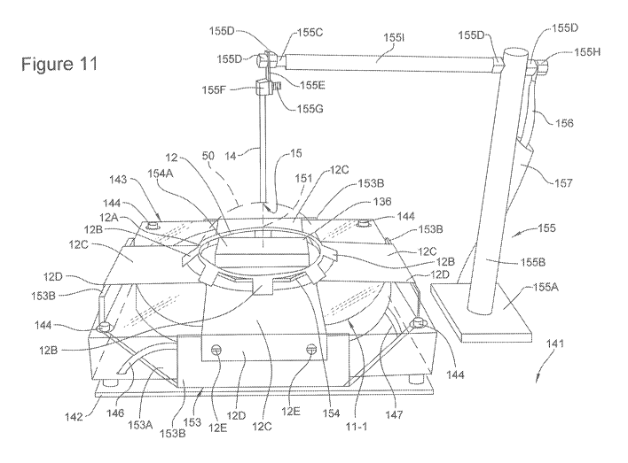
[0072] Fig. 11 illustrates one exemplary embodiment of a system 140 for
plasma generation
that is capable of projecting a plasma-based defensive shield 150 around an
object or area. For
reference sake, the same item numbers used for the system 10 illustrated in
Fig. 1 will also be
used for the system 140 illustrated in Fig. 11 whenever possible.
[0073] More particularly as to the system 140, this system 140 is
configured for positioning
on a base 141. This base 141 for test purposes would be a table but in
application, could be a
CA 02922635 2016-02-26
WO 2014/035365 PCT/US2012/052492
static structure such as a building or a mobile structure such as a vehicle,
airplane or the like.
The system includes a bottom support plate 142 formed of an insulative
plexiglass. This bottom
support plate 142 includes an insulative housing or container 143 positioned
on the top thereof
which preferably comprises top, bottom and side walls that are formed of
sheets of plexiglass
bolted together at the corners through connectors 144. Preferably this housing
143 defines an
enclosed, hollow box although other suitable shapes are possible depending
upon the ultimate
geometric shape of the plasma field 150 being generated and the components
therefor.
[0074] The housing 143 includes an annular EMF generator 11-1 which
comprises a solid
core and a plurality of windings 34-1 wound about the core. These windings 34-
1 are energized
by the deflection field power supply 20 through cables 146 and 147 that are
electrically
connected to the power supply 20 and energize the windings 34-1 to produce the
desired
electromagnetic field. The field generator 11-1 thereby defines an
electromagnet having a
central vertical axis 151 as seen in Figure 11. When energized, the field
generator 34-1 defines
an electromagnetic field 152 which will be described in further detail
hereinafter relative to
Figure 12.
[0075] The system 140 further includes a field generator plate 153 that is
formed of steel and
includes a bottom plate 153A as well as four upstanding side walls 153B. The
bottom plate
153A is disposed vertically between the upper surface of the bottom plate 142
as well as the
opposing bottom surface of the housing 143 while the side plates 153B project
vertically
upwardly and exteriorly of the side faces of this housing 143 such that the
housing 143 nests
within the plate 153. This field generator plate 153 cooperates with and
affects the
electromagnetic field 152 generated by the field generator 11-1 to thereby
assist in defining the
shape and characteristics of this electromagnetic field as will be discussed
in further detail
hereinafter.
[0076] The system 14 further includes the electrodes 12 and 14. More
particularly, the first
electrode 12 in the illustrated embodiment is defined by an annular ring 12A
of conductive wire
or rod material, preferably formed of copper. This electrode ring 12A is
disposed in a vertically
raised position by upstanding support flanges 12B also formed of conductive
copper. These
flanges 12B project downwardly and outwardly and are affixed to horizontal
electrode plates
12C which overly the top surface of the housing 143 and terminate at
downwardly projecting
16
CA 02922635 2016-02-26
WO 2014/035365 PCT/US2012/052492
connector flanges 12D. These connector flanges 12D are fastened to the
upstanding side plates
153 by suitable fasteners 12E. It is noted that all of these components of the
first electrode 12,
namely components 12A-12E are all fixedly joined together and electrically
connected together
and furthermore are electrically coupled to the field generator plate 153 by
their abutting
surfaces. This plate 153 is furthermore connected to the negative terminal of
the second
electrode 12 by an electrical cable attached to this plate 153. As such, the
plate 153 not only
affects the magnetic field but also is part of the electrical circuit to which
the first electrode 12 is
connected.
[0077] As to the electrode ring 12A, this ring 12A encircles or bounds a
center region in
which is disposed an insulative support stand 154 on which an object 155 may
be positioned.
This object 155 is diagrammatically represented as a rectangular box but may
represent any
object or article being protected by the plasma field 150. For example, this
object 155 may be
any one of various objects such as flammable or electrical objects or other
physical structures
which may be disposed in this position without being affected or destroyed by
the surrounding
plasma field 150. Furthermore, while the stand 154 is offset downwardly or
sidewardly relative
to the electrode ring 12A, the stand 154 also may be raised so as to lie
coplanar with the ring
12A.
[0078] As to the second electrode 14, this electrode 14 is suspended above
the stand 154 by a
support assembly 155. This support assembly 155 includes a base plate 155A
which physically
supports an insulative support boom 155B that projects upwardly and is spaced
sidewardly of the
housing 143. On the upper end of the boom 155B, an electrically conductive
support arm or rod
155C is affixed in cantilevered relation so as to project sidewardly outwardly
over and above the
first electrode 12. This support arm 155C is connected to the support boom
155B by suitable
fasteners 155D. The outer distal or free end of the support rod 155C includes
additional
clamping nuts 155D by which an electrically conductive hanger plate 155E is
suspended. This
hanger plate 155E includes a support collar 155F on the bottom end thereof in
which the rod-like
electrode 14 is received and then affixed thereto by a set screw 155G.
Therefore, the second
electrode 14 is electrically connected to the support arm 155C.
[0079] This support arm 155C further has an inner proximal end that has an
electrical supply
cable 156 connected thereto by an additional fastener 155H. An insulator tube
1551 surrounds
17
CA 02922635 2016-02-26
WO 2014/035365 PCT/US2012/052492
the arm 155C between the proximal and distal ends. The cable 156 extends
downwardly into an
insulative tube 157 and thereby is connected to the initiator supply 18 and
current power supply
16 in accord with the diagram of Figure 1. As such, this electrode 14 is
suspended concentrically
above the first electrode 12 in vertically spaced relation.
[0080] Before turning to the operation of the system 140, it will be
understood that the
relative vertical positions of the first and second electrodes 12 and 14
define the overall height of
the plasma field 150 and that these relative vertical positions may be
adjusted or varied to vary
the overall height of the field 150. It has been shown that the electrode 14
may also be placed
generally downwardly in the plane of the electrode ring 12A to define a plasma
field 150 that has
the shape of a flat circular disk rather than the dome shaped plasma field 150
described in further
detail hereinafter.
[0081] Furthermore, the overall diameter of the electrode ring 12A may also
be varied
inwardly or outwardly to further vary the dimension of the plasma field 150.
By shaping the
electrode ring 12A and varying the relative positions of the electrodes 12 and
14, the plasma
field 150 may be varied in its size, shape and overall characteristics.
[0082] Furthermore, the plasma field 150 as discussed in further detail
hereinafter is
governed by the electromagnetic magnetic field 152 in which it is generated
such that the overall
construction of the EMF field generator 11-1 may also be varied to vary the
characteristics of the
plasma field 150. In the illustrated embodiment of Figure 11, this EMF field
is affected by the
positioning of the side plates 153A as well as the overall field
characteristics generated by the
specific EMF field generator 11-1 including the physical structure of the
windings 34-1. The
physical structure of the EMF field generator 11-1 furthermore may be varied
to generate
alternative magnetic field characteristics which thereby vary the
characteristics and shape of the
plasma field 150.
[0083] With the foregoing arrangement, the electrodes 12 and 14 thereby are
electrically
operated in accord with the circuit diagram of Figure 1 and the disclosure
provided above.
[0084] Upon activation of the system 140, a relatively large voltage
difference between
suspended electrode 14 and circular electrode 12 is initially established in
order to initiate a
breakdown of the air gap between the two electrodes, thereby initiating
generation of plasma.
18
CA 02922635 2016-02-26
WO 2014/035365 PCT/US2012/052492
For example, the circular electrode is grounded, while a 150 KV voltage is
applied to the
suspended electrode 14.
[0085] At roughly the same time that an initial voltage is applied to
electrode 14, the EMF
generator 11-1 contained within housing 128 is powered up. Consequently, EMF
generator 11-1
begins to establish an electromagnetic field 152, which is graphically
represented in Fig. 12 as
magnetic field tenser lines. This electromagnetic field 152 and its
characteristics are defined and
shaped by the components of the EMF generator 11-1 described above relative to
Figure 11.
[0086] A particle beam begins to emit from the suspended electrode 14 due
to the high
voltage difference that initially exists between electrodes 12 and 14. In the
current embodiment,
the tip 15 of suspended electrode 14 is cut or shaped to be flat. As a result,
the induced particle
beam emits from the side of the electrode tip 15, thereby directing the beam
more
perpendicularly into the electromagnetic field 152 generated by EMF generator
11-1. If the tip
15 were pointed instead of flat, the particle beam would project more straight
down instead of
perpendicularly into the electromagnetic field 152.
[0087] The induced particle beam initiates the production of plasma by
heating the air and
causing the various gas molecules to dissociate and ionize. If no external
electromagnetic field
152 was present, the particle/plasma beam would generally travel in a straight
line from the tip
15 of suspended electrode 14 to a point on the circular electrode 12 located
on the surface of
housing 128. However, because of the presence of the electromagnetic field 152
generated by
EMF generator 11-1, the particle/plasma beam bends as it travels downward and
outward to the
circular electrode 12. This curved displacement of the particle/plasma beam is
explained by the
Lorentz Force Law, which prescribes that a magnetic field exerts a force upon
an electric charge,
such as a charged or ionized particle, as that charge moves through the
magnetic field. As a
result of these Lorentz forces, such as forces 36 described previously
relative to Figure 26, the
particle/plasma beam curves as it travels, resulting in the path of the beam
to be more circular.
[0088] Plasma begins to build-up as the air continues to heat, resulting in
an increasing
number of gas molecules to dissociate and then ionize to form free positively
and negatively
charged particles. Population inversion eventually occurs when the number of
particles existing
in an excited state (ionized state) exceeds the number of non-ionized
particles occupying a lower
energy state. The process continues until the plasma has reached a state of
near-total popular
19
CA 02922635 2016-02-26
WO 2014/035365 PCT/US2012/052492
inversion and ionic saturation, with the number of ionized or charged
particles greatly exceeding
the number of non-charged particles (e.g., a ratio of eight charged particles
to every non-charged
particle).
[0089] As near-total population inversion occurs, the plasma beam traveling
between the two
electrodes 12 and 14 begins to spiral or rotate about the central axis of the
EMF generator 11-1,
which coincides with the center of the circular electrode 12 and the axis of
the suspended
electrode 14. This rotation of the plasma beam is again the result of Lorentz
forces 36 created by
the electromagnetic field 152 acting on the charged particles of the plasma
beam. As a
consequence of this rotation, the plasma beam generally forms a cone or domed-
shaped field of
plasma with the electrode 14 being on an initiator side of the plasma and the
electrode 12 being
on a receptor side.
[0090] Various forces act upon and influence the movement of the generated
plasma field.
As a result of a balancing of these forces, the plasma field forms a cone or
semi-spherical shaped
sheet or wall of plasma 150 (Figure 12) that rotates about the central axis
151 of the EMF
generator 11-1. These various forces will be discussed with reference to Fig.
13, which depicts a
cross-sectional view of a stabile, cone or dome-shaped wall of plasma.
[0091] Combined thermodynamic and centrifugal forces 160 acting upon the
plasma try to
push out and expand the plasma field 150. The thermodynamic forces are the
intrinsic result of
the heated plasma, and always act to try to expand the plasma field radially
outwardly. As the
plasma field 150 is rotating, it also is subject to centrifugal forces, which
act to also try to expand
the plasma field outwardly.
[0092] The electromagnetic field 152 generated by EMF generator 11-1 also
creates forces
164 that act upon the plasma. Specifically, the electromagnetic field 152
creates Lorentz forces
that act upon the charged plasma particles in a manner that both urge the
plasma to expand
outward as well as push the plasma in. From another perspective, the Lorentz
forces can be seen
as trying to position the plasma field along a specific curved plane that
coincides with the
strongest point of the electromagnetic field 152, thereby imparting greater
spatial and
dimensional stability to the plasma field.
[0093] In addition to forces caused by external magnetic fields, the plasma
150 is also
subject to forces associated with an intrinsic electromagnetic field generated
by the plasma itself.
CA 02922635 2016-02-26
WO 2014/035365 PCT/US2012/052492
As described by Maxwell's Laws, magnetic forces arise due to the movement of
an electrical
charge. Specifically, an electric current flowing through the plasma results
in the creation of an
associated electromagnetic field. This electromagnetic field intrinsic to the
plasma leads to the
creation of additional Lorentz forces that act back upon the plasma. This
phenomenon is
generally referred to as the pinch effect, which prescribes that when an
electric current is passed
through a gaseous plasma, a magnetic field is set up that tends to force the
current-carrying
particles together. The resultant forces 168 of the pinch effect leads to the
plasma to become
compressed or contract in upon itself
[0094] In the above example, a balancing of thermodynamic and centrifugal
forces with the
various Lorentz forces associated with the intrinsic and extrinsic
electromagnetic fields results in
a stabile, thin, cone or rod-shaped wall or sheet of plasma 150. Furthermore,
the interior of the
cone-shaped plasma field 150 not only remains unaffected, but becomes
protected by the wall of
plasma to thereby define an interior protection zone or space 169 disposed
interiorly of or
adjacent to the plasma field 150. The system 140 also could be configured with
the protection
zone being defined by the side of the plasma 150 nearest the electrode 14.
[0095] As previously noted, a sufficiently high enough voltage is initially
applied to
suspended electrode 14 by voltage initiator supply 18 in order to initiate the
formation of plasma.
A sufficient amount of current must also be initially provided to electrode 14
by current power
supply 16 in order to assure that the plasma field 150 starts off with
sufficiently high enough
current levels that exceed a predetermined pinch effect threshold. This
assures that the plasma
field 150 will be subject to the pinch effect from the beginning of its
formation, which is
necessary for the creation of a wall of plasma around the area 169 while not
affecting the interior
of the area 169 or articles disposed in this region.
[0096] Once initiated, the plasma defense shield 150 can be kept in a
steady state with a
substantially lower level of voltage at electrode 14. Accordingly, voltage
levels at electrode 14
only need to be high for initiation of the plasma defense shield. For example,
initiation of a
plasma field may require the application of 150 KV at electrode 14, but once
the field is formed,
it can be maintained with only 800 V at electrode 14.
[0097] As previously discussed, prior systems for electromagnetically
confining plasma,
such as the tokamak, are designed to work with extremely hot, high-energy
plasmas.
21
CA 02922635 2016-02-26
WO 2014/035365 PCT/US2012/052492
Furthermore, these previous systems are configured to encourage particle
collisions, which
results in the generation of even more energy/heat. In contrast, the present
invention as
described in the embodiment above produces a very efficient plasma field.
Specifically, the
present invention is able to reach population inversion and ionic saturation
levels where current
is flowing through the plasma, but the plasma particles are not colliding or
interacting with each
other. Instead, the plasma particles effectively move/rotate in unison.
Compared to prior
systems, the present invention creates a stabile plasma field that loses very
little energy due to
the generation of heat or radiation (i.e., light). Instead, a majority of the
plasma energy gets
turned into rotational forces. By energizing all the atoms to the same energy
level and trapping
them with a magnetic field to a very confined area, the plasma mass starts to
behave like an
armature of an electric motor, with a majority of the energy being applied to
"turn the armature"
or rotate the plasma.
[0098] Accordingly, the present invention is seen to disclose a system and
method for
confining plasma by electromagnetic fields. In addition, the disclosed system
and method
provides for the generation of an efficient and effective defensive shield or
"force field",
whereby a stable, thin sheet of plasma can be projected around the perimeter
of an area much
like a wall, while not adversely affecting anything within the interior of the
area either physically
or electrically. Furthermore, the rapid rotary motion of the plasma particles
as well as the
density of the field produces a pressure gradient that effectively functions
like a solid wall of air
through which an object cannot pass without deflection or damage.
[0099] According to one embodiment, a plasma defense shield could be
continuously
projected around an area needing protection. Alternatively, as previously
mentioned, the system
could incorporate some form of monitoring system capable of detecting incoming
ballistic
projectiles. Such a monitoring system may simply involve the constant
projection of a very low
power plasma field that would be unable to stop projectiles but could be
efficiently maintained
for long periods of time. As an incoming projectile begins to cross the plasma
field, the
impedance of the field would fluctuate. A monitoring circuit detects such
changes in impedance
and, while the projectile was still entering the field, increases the power
level of the plasma field
to the point where it would effectively function as a defensive barrier.
22
CA 02922635 2016-02-26
WO 2014/035365 PCT/US2012/052492
[00100] Alternatively, a plasma-based defensive shield system 200 as described
above could
be combined with a more elaborate military detection system 202 that is
capable of detecting
projectiles 204 by various remote monitoring means such as radar. As
illustrated in Fig. 14A,
such a system would typically keep the plasma-based defensive shield 206
inactive. However, as
illustrated in Fig. 14B, upon detection of an incoming projectile 204, the
system would activate
the shield 206 for a brief period of time, maintaining it until the projectile
has impacted the
shield and be deflected and/or destroyed. See Figs. 14C and 14D. Once the
threat has passed,
the system 200 would automatically deactivate the defensive shield 206. See
Fig. 14E.
[00101] According to an alternative embodiment of the present invention, the
circular or
negative electrode 12 could be replaced by any grounded structure, including
the earth 210 itself
Such a configuration, as illustrated in Fig. 15, would allow for a more
effective and practical
means of protecting non-stationary objects, such as a vehicle 212, with a
plasma-based defensive
shield.
[00102] According to another embodiment, an example of which is also
illustrated in Fig. 15,
the electrode 14 that is typically positioned above the object being protected
could be replaced
with a microwave laser or ultraviolet laser 214 or any other means for
initiating a plasma field.
[00103] In the embodiments described above, a ring-shaped electromagnet was
utilized as the
EMF generator 11. In such embodiments, only the portion of the electromagnetic
field projected
above one pole of the magnet is effectively utilized to aid in the containment
of the plasma field.
However, according to a further embodiment, the ring-shaped electromagnet is
replaced with a
rod-shaped electromagnet that can be completely contained within the vehicle
or object being
protected. See the illustrative example of Fig. 16, which depicts a vehicle
230 incorporating a
plasma-based defensive shield system. Contained within the vehicle is a rod-
shaped
electromagnet 240. When activated, the rod-shaped electromagnet generates an
electromagnetic
field 242 that projects out from both poles of the magnet 240 and could be
used to confine and
shape a plasma-based defensive shield around the entire vehicle 230.
[00104] It is also believed possible to project a plasma-based defensive
shield around any
shaped object in such a manner that the thin sheet of plasma making up the
defensive shield
closely follows the contours of the object. For instance, the object could be
covered in a super
23
CA 02922635 2016-02-26
WO 2014/035365 PCT/US2012/052492
conductor "skin" that allowed for the generation of an electromagnetic
containment field
immediately adjacent the object's surface.
[00105] The primary embodiment above discloses the generation of a defensive
shield by
establishing a stable, free-standing "wall" of plasma roughly shaped in the
form of a cone or
cylinder. Thus, according to a prior example, a ground-based vehicle such as a
taffl( could be
effectively protected by the generation of a conical-shaped plasma-based
defensive shield.
According to an alternative embodiment previously discussed, a more spherical-
shaped
defensive shield can be generated by a system utilizing a rod-shaped EMF
generator. Such a
spherical-shaped field may be more appropriate for the protection of flying
craft such as an
airplane as the defensive shield could completely envelop the plane. Beyond
conical and
spherical-shaped defensive shields, it is believed the present application can
be configured to
generate a defensive shield of numerous other sizes and shapes depending on
the relative
placement of the system components, i.e., electrodes, as well as the size and
shape of the external
electromagnetic field being utilized to shape and confine the plasma field.
[00106] Beyond three-dimensional shapes, the present invention is also capable
of generating
a two-dimensional defensive shield. Specifically, a stabile wall of plasma can
be
electromagnetically confined to form a flat or planar, disc-shaped defensive
shield. Such a
shaped plasma field can be achieved by the combined effects of an
appropriately shaped external
electromagnetic field with, for example, the placement of the two electrodes
12 and 14 within the
same plane so that a particle/plasma beam either projects from side to side or
radially outward.
The resultant disc-shaped defensive shield could be projected across a defined
opening or
entrance to function as a barrier. Possible uses for a "flat" plasma-based
barrier are numerous,
and include, for example, a plasma-based "door" or "window" that could quickly
be projected
into place in order to secure a room or corridor from the passage of physical
objects as well as
atmospheric containment.
[00107] Unlike prior electromagnetic plasma confinement applications such as
those found in
fusion reactors, the present invention generates a relatively efficient plasma
field in which little
energy is lost in the form of heat or radiation. As a result of this
efficiency, a plasma-based
defensive shield in accordance with the present invention can be generated
with relatively low
power requirements. For example, operation of a small system capable of
generating a six inch
24
CA 02922635 2016-02-26
WO 2014/035365 PCT/US2012/052492
diameter plasma-based defensive field may require around 500 Watts and could
be readily
powered by a standard 120 Volt household outlet or other low voltage power
source.
[00108] According to another exemplary embodiment, a plasma-based defensive
shield
system could be configured with some form of projectile detection system, as
previously
discussed, that is capable of momentarily activating the defensive shield at
the appropriate time
necessary for deflecting an incoming projectile. In such an arrangement, the
defensive shield
would typically be inactive, and as such, the system would require little
energy. Upon detection
of an incoming projectile, the system would only require a burst of energy to
briefly project a
plasma field capable of deflecting the projectile. In the above arrangement,
the system could be
powered by a relatively low voltage source by incorporating a Marx generator
or other
functionally equivalent component that is capable of briefly producing a high
energy pulse but be
charged by a lower voltage source.
[00109] In a further embodiment, a larger system could be configured to
generate a 24 foot
diameter defensive shield capable of protecting a land-based vehicle such as a
tank. The
estimated power requirements for this larger system could be a minimum of 10-
15 Kilowatts to
generate a stabile field, with the power requirements increasing depending on
the mass and
kinetic energy of the projectile being deflected. A defensive shield system
such as that above
could readily be accommodated by a modern-day tank, which typically
incorporates generators
capable of producing 40-50 Kilowatts.
[00110] Even significantly larger and more powerful plasma-based defensive
shields should
already be achievable with the current state of technology. As the present
invention need only
briefly project a stabile wall of plasma in order to protect an object or area
from projectiles, the
system would require a power source capable of generating pulses of high
energy. Such
requirements are already achievable with the advent of newer power sources
used in applications
such as high-end military railguns. Once such existing power source, for
example, is the
compensated pulsed alternator (compulsator), which can produce extremely high
amounts of
energy for brief periods of time (e.g. 500 Megawatt pulse of energy).
[00111] While particular embodiments of the present invention have been shown
and
described, it will be obvious to those skilled in the art that the invention
is not limited to the
CA 02922635 2016-02-26
WO 2014/035365
PCT/US2012/052492
particular embodiments shown and described and that changes and modifications
may be made
without departing from the spirit and scope of the appended claims.
26