Note: Descriptions are shown in the official language in which they were submitted.
CA 02922787 2016-03-04
Apparatus and Method for Providing an Interstitial Space
Field of the Invention
The present invention relates to the provision of a monitorable interstitial
space between a
surface of a wall and skin attached to the wall, and in particular to the
provision of monitorable
interstitial spaces around pipes.
Background of the Invention
The advantage of providing twin walls for tanks, such as fuel storage tanks,
by constructing a
monitorable interstitial space between the twin walls is understood and a
number of systems are .
available for providing twin walls. Typically, the integrity of the tank is
monitored by subjecting the
space between the twin walls to a vacuum. If the vacuum fails this indicates
that one of the twin
walls has become porous, for example through mechanical piercing of one of the
walls or through
corrosion.
Some examples of solutions to the above-described problem are described below.
The publication WO 00/32394 describes a method of lining a fuel storage tank
in which a
keying means is applied to the surface of a tank. A corrosion barrier is then
applied to the keying
means. An interstitial grid is then applied to the tank and pliable glass
reinforced plastics material is
laid onto the grid. The glass reinforced plastics material is then exposed to
ultra violet rays to cure
the material and form a hardened inner liner shell for the tank.
An apparatus and method for lining a tank so as provide a monitorable
interstitial space is
described in GB2444486. This apparatus uses sheet material having adhesive
applied to both sides to
attach itself and the other components of the lining to the wall of a tank.
The apparatus and method
described in this invention have been found to be particularly effective in
the lining of underground
and above-ground storage tanks used for storing fuel, acids and other fluids.
1
CA 02922787 2016-03-04
Pipelines are susceptible to corrosion. If a pipeline were to become porous
the
environmental damage resulting could be much worse than that occurring in the
case of a leaking in
tank, since in the case of a pipeline the volume of fluid is not limited in
the same way as it is with a
tank.
In some environments it is necessary to insulate pipelines. Corrosion of the
outer surface of
the pipeline can be a particular problem where pipelines are insulated. This
is because condensation
occurs on the surface of the pipeline and builds up between the surface
thereof and the insulation.
Whilst the apparatus and methods described above in connection with providing
monitor
able interstitial space for tanks are not limited to tanks, and could
theoretically be applied to
pipelines, to do so is not straightforward.
In the case of a tank the environment where the work is carried out is self-
contained,
substantially stable, and controllable. For outdoor pipelines this is not the
case and prevailing
environmental conditions may either severely limit, or prevent the use of the
components of the
above-described apparatus and the equipment required for their installation.
It would therefore be desirable to provide an apparatus and method for
providing an
interstitial space between two walls, one of which may be the wall of a pipe
or pipeline.
Summary of the Invention
According to an aspect of the present invention there is provided an apparatus
for providing
an interstitial space to the surface of a wall, the apparatus comprising:
i. an adhesive layer;
a layer of fluid impervious and weather proof material in the form of a tape,
the tape partially
overlapping itself; =
a layer of spacer material situated between the surface of the tape facing the
wall and the
surface of the adhesive layer distal from the wall;
2
CA 02922787 2016-03-04
and wherein the spacer material has ends which are encapsulated, the apparatus
providing a sealed
interstitial space.
Preferably, the sealed interstitial space is monitorable and more preferably,
a monitoring
means is provided for monitoring the integrity of the sealed interstitial
space.
It is preferred that the sealed interstitial space is subjected to a vacuum
and more preferably,
a vacuum monitoring means is connected to the sealed interstitial space.
The wall may be part of a pipeline. Preferably, the surface of the wall is an
outer surface.
The apparatus may comprise a layer of fluid impervious material between the
fluid
impervious and weather proof tape and the spacer layer. The fluid impervious
material may be a foil
such as metallic (for example aluminium) or plastic foil. The fluid impervious
material may be in
sheet or tape form.
The adhesive layer may be provided by a material that is impregnated with
adhesive, such as
a paper based material impregnated with adhesive. Alternatively, an adhesive
may be sprayed or
otherwise applied to the surface of the wall, or the adhesive may be applied
to the side of the spacer
layer that is to face the outside of the wall, either as a pre-applied
adhesive or during construction of
the apparatus.
A further layer may be provided, in particular where a fluid impervious foil
is used. The
layer is a reinforcement layer situated between the fluid impervious foil and
the fluid impervious and
weather proof tape. The reinforcement layer is preferably a scrim layer and
more preferably the
scrim layer fibre glass or polymer such as polyester and is preferably woven.
The scrim layer may be
in the form of a tape. Alternatively, the reinforcement layer may be a tape
such as a non-permeating
tape, typically with adhesive on one side thereof.
The fluid impervious and weather proof material tape may be a self-
amalgamating tape.
3
CA 02922787 2016-03-04
The apparatus may be applied to only a part of a wall. In the case of a
pipeline, the
apparatus may only be applied where there is a need to be able to monitor the
integrity of the pipe,
for example over weld seams.
A layer of insulation may be provided to the side of the apparatus distal from
the wall to
which the apparatus is applied.
According to another aspect of the invention there is provided a method of
providing an
interstitial space to the surface of a wall comprising the steps of building
up the elements of the
apparatus of the first aspect of the invention on the surface of a wall.
Preferably, the method comprises applying a vacuum to the interstitial space,
and more
preferably the step of monitoring the vacuum.
According to another aspect of the invention there is provided a wall having
an apparatus
according to the first aspect of the invention applied thereto.
Brief Description of the Drawings
In the drawings, which illustrate preferred embodiments of the invention, and
are by way of
example:
Figure 1 is a schematic representation of a pipeline having an apparatus
according to the
invention applied to the outer surface thereof;
Figure 2 is a schematic representation of a pipeline having an apparatus
according to another
embodiment of the invention applied to the outer surface thereof;
Figure 3 is a schematic representation of a pipeline having an apparatus
according to another
embodiment of the invention applied to the outer surface thereof;
Figure 4 is an exploded view of the apparatus illustrated in Figure 1 in a
partial state of
assembly;
4
CA 02922787 2016-03-04
Figure 5 is a cross-sectional elevation of an insulated pipeline according to
another
embodiment of the invention; and
Figure 6 illustrates a further embodiment of the apparatus of the invention.
Detailed Description of the Preferred Embodiments
Referring now to Figure 1, there is shown a pipeline 1 to which the apparatus
of the
invention is attached. The apparatus comprises a plurality of layers. The
first layer 2 provides an
adhesive to which the second layer 3 is attached.
In the illustrated example, the first layer 2 is formed by a layer of flexible
material 2 coated
with adhesive on both sides thereof. In the present example the flexible
material is a paper
impregnated with adhesive. Each side of the flexible material 2 is typically
covered with a layer of
peel-off material which when peeled off reveals the sticky surface. The peel-
off layer is removed
from one surface of the flexible material 2 and that surface is presented up
to and press on to the
outer surface of the wall 1. With the peel-off material removed from the other
surface of the flexible
material 2 of the first layer, the second layer 2, which is a layer of non-
woven grid material 3 is
attached to the surface of the flexible material 2 of the first layer that is
distal from the outer surface
of the pipeline 1. The non-woven grid is open and highly permeable, and in the
present example a
thermoplastic. The adhesive applied to the surface of the flexible material 2
is sufficient to hold the
layer of non-woven grid material 3 onto the flexible material 2. However,
additional adhesive, either
in a layer or in spots may be provided between the flexible material 2 and the
non-woven grid
material 3.
A third layer 4 is formed by a fluid impervious layer comprising a foil sheet
having adhesive
applied to at least one side thereof. Prior to attachment of the foil sheet to
the non-woven grid 3 a
peel off layer is removed from the adhesive covering one side of the foil
sheet. This adhesive
attaches the foil sheet to the non-woven grid 3.
CA 02922787 2016-03-04
A fourth sealing layer 5 is formed by wrapping a fluid impervious and weather
proof tape
around the pipeline, over the top of the previously applied payers. The fluid
impervious tape utilised
in the illustrated example is a self-amalgamating tape, that is when the tape
is stretched or tensioned
over itself as it is wrapped around the pipeline, the overlapping regions of
the tap unite or
amalgamate to form a continuous weather-proof layer. In an alternative, the
tape may be provided
with has adhesive to one side thereof, this adhesive providing for the the
tape to attach to the foil 4
and where the tape overlaps, to itself.
Figure 2 illustrates another embodiment of the invention in which an
additional layer 6 is
provided between the fluid impervious foil sheet 4 and the fluid impervious
tape 5. The layer 6
comprises a scrim layer, which in the present example is formed of woven fibre
glass or polymer
such as polyester. In the embodiment illustrated in Figure 2, the scrim layer
is a separate layer that is
attached to the foil sheet 4 by a suitable adhesive. The adhesive may be
provided on the underside of
the scrim layer or on the outer side of the foil sheet. In either case, the
adhesive would be covered
with a peel off layer covering the adhesive until it is required. As an
alternative to a scrim layer, the
layer 6 may be a tape, such as non-permeating tape. Typically, such a non-
permeating tape would
have adhesive to one side thereof.
The function of the layer 6 is to protect the foil 4 from forces exerted
thereon by the tape 5
during its application, which forces might tear the foil 4.
The function of the non-woven grid material 3 together with the layers of
material between
which it is sandwiched is to provide a monitorable interstitial space.
Monitoring is typically achieved
by applying a vacuum to the interstitial space and monitoring the vacuum. If
the wall 1 of the tank
or the outer layer of the composite material is compromised the vacuum will
fail.
Figure 3 illustrates another alternative embodiment of the invention. In this
embodiment
the foil sheet 4 is omitted. The tape 5 is therefore applied directly over the
non-woven grid material
3.
6
CA 02922787 2016-03-04
In Figure 4 it can be seen that the layer 4 extends beyond the layer of non-
woven grid
material 3. The foil sheet is pressed on to the adhesive provided by the layer
2, thereby encapsulating
the layer 3. In the embodiment illustrated in Figure 3, where the foil sheet 4
is omitted, the tape 5
would extend beyond the end of the layer 3, encapsulating this layer.
By encapsulating the layer 3, a sealed interstitial space is formed to which a
vacuum may be
applied.
The layers 2, 3,4 and 6 may be applied either in the form of sheet material or
each layer may
be formed of tape. The advantage of providing each layer as a tape is that the
application of each
layer to the pipeline may be performed using tape applicators. This is also
the case for the fluid
impervious tape 5. The function of tape applicators, also known as tape
wrappers is known in the
art.
The advantage of using a fluid impervious tape is that application of the tape
can be carried
out in almost any weather conditions and either without specialist equipment
or with specialist
equipment that is simple to operate and can be used in most weather
conditions.
Figure 5 iLlustrates an insulated pipeline where a layer of insulation 7 is
situated to the
outside of the fluid impervious tape 5.
By providing a vacuum between the insulation 7 and the outer surface of the
pipeline 1,
condensation on the outer surface of the pipeline 1 is very much reduced
because the moisture
containing air is evacuated from the air space adjacent the outer surface of
the pipeline 1.
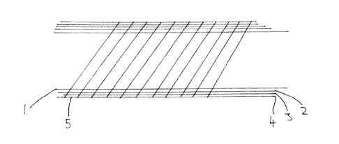
Figure 6 illustrates an embodiment of the invention where the apparatus is
applied only to a
small part of a pipeline 1. The apparatus comprises a layer of adhesive 2, a
layer 3 of spacer material
and fluid impervious and weather proof tape 5. The adhesive layer 2 extends
beyond the peripheral
edge of the layer 3 of spacer material. The tape 5 is held down by the
adhesive 2. The adhesive layer
2 may extend beneath the layer 3 or may simply surround the layer 3. Where the
latter is the case, the
adhesive may be provided on the underside of the tape 5. The tape may be
wrapped around the
7
CA 02922787 2016-03-04
pipeline, but the monitoratble interstitial space only may only be provided
for a small part of the
pipeline. In such an embodiment the adhesive layer 2 and the layer 3 of spacer
material would be as
shown in Figure 6 but the tape 5 would be as shown in Figure 1.
In all the above-described embodiments, where a surface is corroded, the
corrosion would
be repaired before applying the apparatus of the invention. This may involve
blasting, grinding or
sanding back to bare metal and may also involve a protective paint or resin.
All of the features disclosed in this specification (including any
accompanying claims,
abstract and drawings), and/or all of the steps of any method or process so
disclosed, may be
combined in any combination, except combinations where at least some of such
features and/or
steps are mutually exclusive.
Each feature disclosed in this specification (including any accompanying
claims, abstract and
drawings), may be replaced by alternative features serving the same,
equivalent or similar purpose,
unless expressly stated otherwise. Thus, unless expressly stated otherwise
each feature disclosed is
one example of a generic series of equivalent or similar features.
8