Note: Descriptions are shown in the official language in which they were submitted.
CA 02922920 2016-02-29
WO 2015/028821 PCT/GB2014/052634
Flood Defence Barrier
The present invention relates to flood defence barriers, particularly those
which can be
deployed quickly and easily and can be removed from the deployment site
without leaving
behind contaminated fill material.
Flooding is a growing problem in many parts of the world. It is commonly dealt
with by
erecting barriers to keep rising water levels out of certain areas. Such
barriers generally
have to be erected quickly and easily, especially as weather conditions are
often adverse
just before flooding occurs. Additionally, there is often little or no prior
warning of flooding
and so it would be beneficial to be able to use materials readily available at
the site at which
the barriers are to be deployed.
Commonly used flood barriers comprise bags filled with soil or sand, which are
then
wrapped in a water impermeable material such as polyethylene, This process can
be time
consuming and cannot be guaranteed to result in a strong, fully water
impermeable barrier. It
is common for small gaps to occur in between the bags, especially at their
base. Water can
then pass through these gaps, resulting in leakage. The amount of water
passing through
the barrier depends on the force of the flood, though it can be significant.
The force of the
water can also create a channel in the ground underneath the barrier, thereby
increasing the
amount of water that can pass through the barrier.
Once the flooding has subsided, disposal of the material that was used to fill
the bags also
becomes problematic. The fill material is generally contaminated with
materials such as
sewage that are present in the floodwater, which seeps into the bag during the
flooding.
Unfortunately, it is common practice to remove the barriers by simply cutting
open the bags
and removing the contaminated fill material, which is generally left at the
site. This practice
has both environmental and safety consequences for the surrounding area.
EP1731678 discloses a flood barrier comprising a plurality of individual
compartments.
These compartments are attached by screws, nails, clamps or the like, which
extend
between adjacent side walls of adjacent individual compartments. A plurality
of individual
compartments can be connected to form a unit and two units can be attached
together in the
same manner as the individual compartments within each unit are connected,
i.e. using
screws, nails, clamps or the like.
1
CA 02922920 2016-02-29
WO 2015/028821 PCT/GB2014/052634
Whilst this offers some improvements, there is still a need for a flood
barrier that is quick and
easy to erect, with improved leakage resistance and that allows removai of the
contaminated
fill material from the site.
The present invention provides a flood defence barrier comprising:
a. a first plurality of individual compartments connected together and
provided
with a continuous length of water impermeable material extending across the
individual compartments along at least one side of the barrier;
b. a second plurality of individual compartments connected together and
provided with a continuous length of water impermeable material extending
across the individual compartments along at least one side of the barrier; and
c. fastening means for fastening the first plurality of individual
compartments to
the second plurality of individual compartments.
The fastening means may comprise any suitable fastening means, such as eyelets
made of,
for example, plastic or metal on each plurality of individual compartments,
which are then
connected by means such as a cable tie. The cable ties may be made of, for
example, metal
or plastic and may be releasable or non-releasable, Alternatively, other means
such as a
water impermeable zip (for example the MaxiGrip MX 20), VelcroTm or C-rings (C-
shaped
metal staples that are then deformed into a circle, thereby connecting the two
compartments) can be used. Any number of such fastening means may be used at
each join
to connect two individual compartments together.
The individual compartments in each plurality may also be connected via
fastening means
such as those described above. Again, any number of such fastening means may
be used at
each join to connect two individual compartments together. When eyelets arid
cable ties, or
C-rings, are used, there are preferably four fastening means evenly spaced
along each joint
between the two individual compartments. In other words, there are four
fastening means at
the front of the barrier between each individual compartment and four
fastening means at the
back of the barrier between each individual compartment.
The present invention also provides a flood defence barrier comprising a first
plurality of
individual compartments connected by a first, non-releasable fastening means,
wherein the
plurality of individual compartments comprises at least one second,
releasable, fastening
means effective for releasabiy fastening the first plurality of individual
compartments to a
second plurality of individual compartments.
2
CA 02922920 2016-02-29
WO 2015/028821 PCT/GB2014/052634
By releasable, it is meant that the fastening means can be unfastened without
destruction of
the means, such that the means can be re-fastened after said unfastening. in
contrast, non-
releasable fastening means can only be unfastened either by destruction of the
means or
their removal from the barrier, so that they cannot subsequently be re-
fastened. In one
embodiment, the first, non-releasable fastening means comprises a continuous
length of
material, which may be water impermeable.
Used herein, reference to a "fastening means" refers to the fastening means
for fastening
the first plurality of individual compartments to the second plurality of
individual
compartments. Preferably, the fastening means may be provided on at least one
of the
compartments of a plurality of individual compartments. The at least one
compartment
provided with a fastening means may be an end compartment. Additionally or
alternatively,
the complementary fastening means of a second plurality of individual
compartments may be
on an end compartment. Preferably the fastening means can be fastened and
optionally also
unfastened without the need for additional equipment.
The individual compartments of the present invention are self-contained units,
which are
connected by a non-releasable fastening means, which may be a continuous
length of water
impermeable material extending across the individual compartments along at
least one side
of the barrier. Preferably, the individual compartments are bags. Each
individual
compartment preferably comprises side walls and a base. Preferably, the
individual
compartments are designed to tessellate and so may, for example, be cuboid. At
least part
of each individual compartment may comprise a water impermeable material. The
term "side
walls adjacent to another individual compartment" used herein refers to
adjacent side walls
of adjacent individual compartments that face one another.
Some or all of the individual compartments can contain a fill material.
Preferably, all of the
individual compartments contain a fill material. The NI material may be
selected from sand,
earth, soil, stones, rocks, rubble, concrete, debris and combinations of two
or more thereof.
This fill material provides stability to the barrier and is preferably a
material found naturally
around the deployment site.
A means for preventing a fill material from falling between adjacent
individual compartments
may be present. This is particularly important when the fill material is being
introduced to the
compartments, especially when the fill material is a fine material such as
sand. This means
may comprise a material extending between the compartments and fastened to the
inside of
each of the side walls adjacent to the other individual compartment. The
material may be
fastened by, for example, staples or stitches. Optionally, the means may be
attached to the
3
CA 02922920 2016-02-29
WO 2015/028821
PCT/GB2014/052634
inside of one of the side walls adjacent to the other individual compartment
and can
subsequently be attached to the other side wall.
The flood defence barrier is preferably self-supporting. The flood defence
barrier is therefore
capable of standing erect before the fin material is inserted. In order to
achieve this, some or
ail of the individual compartments may be made of a stiff fabric. Additionally
or alternatively,
some or all of the individual compartments may be made of polypropylene
Further, some or
ail of the individual compartments may comprise a stiffening material to
provide or enhance
rigidity. The stiffening rnaterial may be present on ail sides of the
individual compartment.
The stiffening material may be any suitable material and may comprise one or
more of a
geogrid, wood and/or polypropylene. By geogrid, it is meant a material that is
conventionally
used for grass or soil reinforcement. Preferably, correx is used to provide or
enhance rigidity.
This stiffening material can be inserted as one or more panels. The panels may
be placed
against the inside of a side wall of an individual compartment, or may be
inserted into a
pocket formed within a side wall of an individual compartment. The pocket can
then be
closed, sealing in the panel. Two adjacent panels may be used on each of two
opposite side
walls, such that the side walls can fold at a point along their length. This
allows the barrier to
concertina when not filled. Additionally or alternatively, the side walls
adjacent to another
individual compartment may comprise one panel, while the side walls
perpendicular thereto
may comprise two panels, such that the perpendicular side walls can fold to
allow the barrier
to be compressed. The panels may not extend along the entire length of the
side wall, which
allows the walls to fold and thereby allows the barrier to be compressed.
Alternatively, the material can be rolled into a cylinder and placed within a
compartment,
such that it expands to the width of the compartment but maintains a
cylindrical shape.
Some or all of the individual compartments may comprise an openable base. This
allows the
fill material to be easily released from the individual compartments once the
barrier is
dismantled. Preferably, the base remains closed until such an openable feature
is used, so
that the compartments, including the fill material, can be removed from the
site of
deployment. The fill material can then be released as and when is appropriate.
However, the
base is preferably flat and/or smooth, so as to minimise potential passages
for water
underneath the plurality of individual compartments. Any suitable means may be
used to
allow the openable base to open. In one arrangement, the openable base may
comprise an
opening which is held closed by a toggle mechanism or the like that can be
released to allow
the opening to open.
4
CA 02922920 2016-02-29
WO 2015/028821
PCT/GB2014/052634
Further, some or all of the individual compartments may comprise a lifting
means. Such a
lifting means may comprise handles on the top edges of the inddual
compartments. The
lifting means helps the individual compartments to be removed from the flood
barrier once
the flood has subsided.
The plurality of individual compartments may comprise any number of individual
compartments. Preferably, the number is between 2 and 15, more preferably
between 5 and
12 and even more preferably, 10.
The plurality of inddual compartments may be arranged side-by-side, so as to
form a line
of individual compartments that is one compartment deep. In this linear
embodiment, the
plurality of individual compartments has two long sides, which extend along
the length of all
of the individual compartments and two short sides, which are equal to the
depth of a single
compartment. In this embodiment, a continuous length of water impermeable
material may
extend along at least one of the long sides. The fastening means for fastening
the plurality of
individual compartments to a second plurality of individual compartments is
preferably at one
or both ends of the long side and may be pieced on the long side and/or on the
short side.
The flood defence barrier is preferably water impermeable along the entirety
of one of its
sides. This means that the point at which a first plurality of individual
compartments is
fastened to a second plurality of individual compartments is water
impermeable. In the linear
embodiment discussed above, this side is preferably one of the long sides. The
opposite
side of the plurality of individual compartments to the water impermeable side
is preferably
water permeable. This means that the floodwater will be stopped by the
barrier, but that any
water that does leak into the individual compartments can then escape. In a
further
embodiment, the water impermeable side is differently coloured to the opposite
side. This
allows easy identification of the direction in which the barrier should face,
as well as making
it obvious that one of the plurality of individual compartments in a barrier
comprising multiple
pluralities has been placed the incorrect way round. Additionally or
alternatively, the
fastening means for fastening the first plurality of individual compartments
to the second
plurality of individual compartments rnay be arranged such that it is not
possible to attach
two pluralities of individual compartments in the wrong configuration.
The first, non-releasable fastening means may comprise screws, nails, clamps
and the like.
Alternatively, the first, non-releasable fastening means may comprise a water
impermeable
material extending along a side of the plurality of individual compartments,
which may be
connected to at least some of the individual compartments by stitches, staples
or the like.
This side may be an external side of the plurality of individual compartments
and may also
be a side perpendicular to a side of an individual compartment which is
adjacent to another
CA 02922920 2016-02-29
WO 2015/028821
PCT/GB2014/052634
vidual compartment. In the iinear embodiment discussed above, this side is
preferably
one of the long sides, In one embodiment, a second length of material extends
along a side
opposite that along which the water impermeable material extends. This second
material
may be water permeable. The water impermeable material may be used to connect
all of the
individual compartments in the plurality. The water impermeable material
preferably extends
along a side of every individual compartment in the plurality.
The water impermeable material may extend beyonci the side of the plurality of
individual
compartments such that it can cover the fastening means for fastening the
first plurality of
individual compartments to the second plurality of individual compartments. in
one
embodiment, the material comprises the fastening means to attach the first
plurality of
individual compartments to a second plurality of individual compartments.
Preferably, the
material may extend underneath the or each plurality of individual
compartments. This
reduces the leakage through the barrier, by reducing the formation of channels
in the ground
caused by the water and thereby reducing the passage of floodwater underneath
the barrier.
It may therefore be preferable to include a separate section of material on
the water
impermeable side of the plurality of individual compartments that extends
underneath the
barrier,
The fastening means for fastening the first plurality of individual
compartments to the second
plurality of individual compartments may comprise screws, nails, clamps and
the like. The
fastening means for fastening the first plurality of individual compartments
to the second
plurality of individual compartments may also or alternatively comprise means
that can be
unfastened without destruction of the means, such that the means can be re-
fastened after
said unfastening. In one embodiment, the fastening means for fastening the
first plurality of
individual compartments to the second plurality of individual compartments may
be one or
more of a zip, buckles or other arrangements. The fastening means for
fastening the first
plurality of individual compartments to the second plurality of individual
compartments may
be water impermeable. A plurality of buckles may be used and preferably, two
or three
buckles are used. Such fastening means are generally expensive and so
incorporating these
fastening means once every plurality of individual compartments reduces cost
compared to
barriers in which a fastening means is included between each individual
compartment. The
fastening means is preferably covered by a section of material, which is
preferably water
impermeable and acts to further reduce leakage through the barrier, This
section of material
may or may not comprise the water impermeable material, as discussed above,
The same or
different fastening means may be used at each point where the fastening means
is present.
6
CA 02922920 2016-02-29
WO 2015/028821 PCT/GB2014/052634
Preferably, both buckles and a zip are used. The buckles may be attached to
each end of
two piuralities of individual compartments and may take a majority of the
stress of holding
the two pluralities together, which would make it easier to close the zip. The
zip may be
attached to a section of material covering the buckles and provides improved
water
impermeability as well as an additional fastening means. The section of
material may or may
not comprise the water impermeable material of one or both of the pluralities
of individual
compartments.
When the fastening means is present on the water impermeable material, the
fastening
means itself preferably acts to create a water impermeable seal. For example,
water
impermeable zips such as the MaxiGrip MX 20 can be used.
The fastening means for fastening the first plurality of individual
compartments to the second
plurality of individual compartments may be provided only on one side of the
plurality of
individual compartments. Alternatively, the fastening means for fastening the
first plurality of
individual compartments to the second plurality of individual compartments are
provided on
opposite sides of the plurality of individual compartments. in the linear
embodiment
discussed above, the water impermeable material may extend along one or both
of the long
sides. The fastening means for fastening the first plurality of individual
compartments to the
second plurality of individual compartments may be present on one or both of
the short
sides, or on the long side close to one or both of the short sides.
Additionally or alternatively,
the fastening means for fastening the first plurality of individual
compartments to the second
plurality of individual compartments may be present on one or both of the long
sides, or on
the short side close to one or both of the long sides.
Additionally, there may also be fastening means (releasable or otherwise) as
described
above between adjacent individual compartments within the or each plurality of
individual
compartments. This may provide increased strength and stability to the barrier
and such
fastening means may also be used to pull the compartments together before they
are filled,
and/or while in the case of a releasable fastening) making it easier to remove
the individual
compartments separately from the plurality of individual compartments when
disassembling
the flood defence barrier. For example in some embodiments of the invention
releasable
fastening means, such as buckles or zips, may be provided between individual
compartments in the or each plurality of individual compartments.
Conveniently, such
fastening means may be provided on the compartments on the opposite side of
the barrier
from the continuous sheet of water impermeable material.
To further reduce leakage, the flood defence barrier of the present invention
may further
comprise a compressible member extending at least part of the distance from
the top to the
7
CA 02922920 2016-02-29
WO 2015/028821 PCT/GB2014/052634
bottom of at least one side of the plurality of individual compartments.
Addonally or
alternatively, the flood defence barrier may comprise a compressible member
extending at
least part of the distance along the base of at least one side of the
plurality of individual
compartments. In the linear embodiment discussed above, the compressible
member is
preferably on one or both of the short sides of the plurality of individual
compartments.
Said compressible member may comprise foam and may further comprise a hollow
foam
tube. Preferably, the compressible member is resiliently compressible. In a
further
embodiment, a compressible member extending at least part of a distance along
one side of
a plurality of individual compartments is offset from a compressible member
extending at
least part of a corresponding distance along an adjacent side of a second
plurality of
individual compartments when the two are attached by a fastening means for
fastening the
first plurality of individual compartments to the second plurality of
individual compartments.
The compressible member is preferably compressed against a surface adjacent
the side of
the plurality of individual compartments (which may be another plurality of
individual
compartments) as the individual compartment on which it is placed is filled
with a fill material.
This acts to further decrease leakage as the compressible member forms a water
impermeable seal. Preferably, leakage is reduced by around 10%.
The flood defence barrier according to the present invention may comprise any
number of
pluralities of individual compartments. Preferably, there are more than two
pluralities of
individual compartments. This provides a barrier of adjustable length,
depending on the
requirements of the deployment site
Also provided is a method for deploying a flood defence barrier according to
the present
invention, comprising transporting the folded plurality of individual
compartments to a
deployment site, unfolding the plurality of individual compartments and
filling each individual
compartment with a fill material, before or after which the plurality of
individual compartments
is attached to another group of one or more individual compartments by the
fastening means
for fastening the first plurality of individual compartments to the second
plurality of individual
compartments. In an embodiment, an individual compartment at the end of the
flood defence
barrier is filled with a fill material and tension is subsequently applied to
the opposite end of
the flood defence barrier so as to unfold and erect the plurality of
individual compartments.
Alternatively, the pluralities of individual compartments may be provided at
the deployment
site erected and optionally also filled.
When the flood defence barrier of the present invention is to be removed, the
fastening
means for fastening the first plurality of individual compartments to the
second plurality of
8
CA 02922920 2016-02-29
WO 2015/028821
PCT/GB2014/052634
individual compartments may be released, so as to separate the pluralities of
inddual
compartments. in an embodiment, the water impermeable material is destroyed so
as to
separate the individual compartments. Each individual compartment may then be
removed
and taken away from the site separately. The fill material in each individual
compartment
may be released at the site, or may be released once the individual
compartment has been
taken away from the site.
Also provided is the use of a flood defence barrier according to the present
invention as a
barrier against elemental forces, such as flooding.
Any of the above embodiments of the present invention may further comprise a
lid extending
at least partially over the top of one or more of the individual compartments.
This lid prevents
the fill material from accidentally being removed from the compartment, for
example by water
or wind. Removal of the fill material would mean that the barrier becornes
lighter and so can
be more easily displaced.
Preferably, the lid extends over the entirety of the top of the individual
compartment. The lid
may be fastened to the individual compartment using any suitable means. The
lid itself may
comprise any suitable material, in one embodiment, the lid is at least
partially formed by the
water impermeable material extending from the side of the barrier at least
partially over the
top of the barrier. in this embodiment, at least a portion of the impermeable
material may be
taller than the one or more individual compartments along which it extends, so
that it can
reach over the top of one or more of the compartments, thereby creating a lid.
The barrier may also include a reflective material, which increases the
visibility of the barrier
in the dark. Preferably, this reflective material is on the rear of the
barrier, on the opposite
side to the water impermeable material. The reflective material may be at any
suitable
position, such as on the lifting means, the lid or the individual compartments
themselves,
One or more embodiments of the invention are described further hereinafter, by
way of
example only, with reference to the accompanying drawings in which:
Figure I demonstrates the top view of a plurality of individual compartments;
Figure 2 demonstrates the front view of the plurality of individual
compartments as shown in
Figure 1, adjacent to a second plurality of individual compartments;
Figure 3 demonstrates the back view of the plurality of individual
compartments as shown in
Figure 1, adjacent to a second plurality of individual compartments;
9
CA 02922920 2016-02-29
WO 2015/028821
PCT/GB2014/052634
Figure 4 demonstrates the top view of a plurality of individual compartments
adjacent to
another plurality of inddual compartments and further comprising compressible
members;
Figure 5 demonstrates the side view of a plurality of individual compartments
adjacent to
another plurality of individual compartments and further comprising
compressible members;
Figure 6 shows the flood barrier of the present invention when deployed
against floodwater:
Figure 7 demonstrates the plurality of individual compartments shown in Figure
1, further
comprising stiffening rneans;
Figure 8 demonstrates the front view of the plurality of individual
compartments shown in
Figure 2, further comprising means for preventing a fill material from falling
between
adjacent individual compartments;
Figure 9 demonstrates a rear view of a further embodiment of the present
invention,
comprising a lid extending over the top of the individual compartments; and
Figure 10 demonstrates a side view of one of the individual compartments shown
in Figure
9,
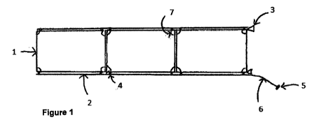
Looking at the drawings in more detail, Figure 1 demonstrates the top view of
a plurality of
individual compartments 1, connected by a continuous length of water
impermeable material
2, in this embodiment, the water impermeable material 2 comprises stitches 4
to attach the
material to the individual compartments 1. Fastening means 3 are present on
the end
compartment of the plurality of individual compartments 1, in the form of
buckles. An
additional fastening means is shown as a zip 5 on the end of a section of
material 6, which is
an extension of the water impermeable material 2. Also illustrated are lifting
means 7, in the
form of handles at each corner of the individual compartments 1,
Figure 2 demonstrates the front view of the plurality of individual
compartments 1 as shown
in Figure 1, adjacent to a second plurality of individual compartments 1, The
individual
compartments 1 in each plurality are connected by a water impermeable material
2. The
fastening means 3 in this case comprising three buckles) are present on both
end
compartments of each plurality of individual compartments 1, The section of
material 6 will
extend over the fastening means 3 and will be attached to the adjacent
plurality of individual
compartments 1 using the zip 5, thereby reducing leakage of floodwater between
the
pluralities of individual compartments 1,
Figure 3 demonstrates the back view of the plurality of individual
compartments 1 as shown
in Figure 1, adjacent to a second pluraiity of individual compartments 1, The
individual
CA 02922920 2016-02-29
WO 2015/028821
PCT/GB2014/052634
compartments I in each plurality are connected by a water impermeable material
2. The
fastening means 3 (in this case comprising three buckles) are present on both
end
compartments of each plurality of individual compartments 1.
Figure 4 demonstrates the top view of a plurality of individual compartments 1
adjacent to
another plurality of individual compartments 1, each of which are connected by
a water
impermeable material 2. Both individual compartments 1 comprise a fastening
means 3.
Each individual compartment I further comprises a compressible member 9
extending the
distance from the top to the bottom of the side of the individual compartment
1, in this
embodiment, the two compressible members 9 are offset from one another. One of
the
individual compartments 1 further comprises a compressible member 8 extending
part of the
distance along the base of the individual compartment I .
Figure 5 demonstrates the side view of the plurality of individual
compartments 1 as
demonstrated in Figure 4. Again, this figure shows a plurality of individual
compartments I
adjacent to another plurality of individual compartments 1, each of which are
connected by a
water impermeable material 2. Both individual compartments 1 comprise a
fastening means
3. Each individual compartment 1 further comprises a compressible member 9
extending the
distance from the top to the bottom of the side of the individual compartment
1. One of the
individual compartments 1 further comprises a compressible member 8 extending
part of the
distance along the base of the individual compartment I.
Figure 6 shows the flood barrier of the present invention when deployed
against floodwater
11. The individual compartment 1 is placed on the ground 10, with the water
impermeable
material 2 facing the floodwater 11, An opposite length of material 16 extends
along the side
opposite the water impermeable material and is preferably water permeable. In
this
embodiment, a section of the water impermeable material 2 extends underneath
the
individual compartment I to further reduce leakages. The two compressible
members 8, 9
are also illustrated.
Figure 7 demonstrates the plurality of individual compartments 1 shown in
Figure 1, further
comprising stiffening means 12, 13, Stiffening means 13 extend along the side
walls of the
individual compartments adjacent to another individual compartment and
comprise a single
panel placed against the inside of the side wall. Stiffening means 12 extend
along the side
walls perpendicular to the side walls adjacent to another individual
compartment. Two
stiffening means 12 are placed adjacent one another to extend along the full
length of the
inside of the side wall. This allows the perpendicular side wall to fold in
the middle, allowing
the plurality of individual compartments 1 to collapse.
11
CA 02922920 2016-02-29
WO 2015/028821
PCT/GB2014/052634
Figure 8 demonstrates the front view of the plurality of individual
compartments 1 shown in
Figure 2, further comprising a means for preventing a fill material from
falling between
adjacent individual compartments 14. The means 14 comprises a material
extending
between adjacent individual compartments 1 and fastened to the inside of each
of the
adjacent side was, The means 14 is fastened by fastening means 15, which may
comprise
stitches or staples.
Figure 9 demonstrates a rear view of a plurality of individual compartments 21
according to a
further aspect of the present invention, which comprises a lid 22 extending
over the top of
each of the individual compartments 21. Lid 22 comprises a top portion 22a and
a front
portion 22b that extends along the front side of the individual compartments
21, The front
portion 22b is a water impermeabie material comprising polythene that extends
along the
front side of the individual compartments 21. The lid 22 then reaches over the
top of the
individual compartments 21 to form the top portion 22a, so that the front
portion 22b and the
top portion 22a are continuous. It is this top portion 22a that prevents the
fill material from
accidentally being removed from the individual compartment 21. The edge of the
top portion
22a furthest away from the front portion 22b is then attached to the
individual compartments
21 by Velcro,
Figure 10 demonstrates a side view of one of the plurality of individual
compartments 21
shown in Figure 9, Front portion 22b of the lid 22 is shown extending along
the height of the
individual compartment 21 and underneath it. This provides a means for
anchoring the lid
material, as well as providing a waterproof front to the individual
compartment 21. Front
portion 22b also extends over the top of the individual compartment 21 to form
the top
portion 22a of the lid 22. Also shown are lifting means 27 in the form of
handles at either side
of the individual compartment 21.
Figure 10 also demonstrates an enlarged view of the top corner of the
individual
compartment 21, in which the material of the lid 22 extends over the top of
the individual
compartment 21 and is stapled to the inside thereof using staples 23.
12