Note: Descriptions are shown in the official language in which they were submitted.
CA 02923130 2016-03-03
WO 2015/041864 PCT/US2014/054204
INTEGRATED VEHICLE CONTROL SYSTEM AND APPARATUS
CROSS REFERENCE TO RELATED APPLICATION
[0001] This application is a continuation-in-part of United States Patent
Application Serial No.
13/859,962, which is a continuation of United States Patent Application Serial
No. 13/465,468
filed May 7, 2012 and issued as United States Patent No. 8,446,265 on May 21,
2013, which is a
continuation-in-part of United States Patent Application 12/555,477 filed
September 8, 2009 and
issued as United States Patent No. 8,198,996 on June 12, 2012, which are
incorporated herein by
reference to the extent allowed by law.
FIELD OF THE INVENTION
[0002] The present invention relates to a vehicle control system and apparatus
for operating the
vehicle's components that is integrated into the rim of a vehicle's steering
wheel in such a way as
to be fully operable without a driver of the vehicle being required to remove
hisilier hands from
the steering wheel,
BACKGROUND OF THE INVENTION
[0003] Vehicle turn signals, while having been in use on commercially
available motor vehicles
for about 70 years, have changed little since their first application. More
recently, vehicles have
been equipped with computer-operated functionality which allows the vehicle's
driver or
operator to control the vehicle's radio, compact disc player, connected
devices, cellular telephone
and navigation system, and other components through a central controller.
[0004] A vehicle steering wheel is commonly comprised of a column, central hub
and annular
ring with various components including a turn signal activation switch or
switches. Typically
turn signal lights are operated by a "stalk switch" or lever located to one
side of the steering
wheel. The stalk switch is moved upward to signal a right-hand turn and
downward to signal a
left-hand turn. When the stalk switch is moved up, lights located generally in
the front and rear
right side fenders begin to blink. Similarly, when the stalk switch is moved
down, lights located
generally in the front and rear left side fenders begin to blink. More
typically, the stalk switch
includes four positions, two up and two down. The first positions, either up
or down, operate the
turn signals but the stalk switch returns to the off position, or center, when
released. The second
of the positions maintains the turn signals on even when the stalk switch is
released and shuts off
CA 02923130 2016-03-03
WO 2015/041864 PCT/US2014/054204
after the steering wheel has been turned a fixed rotation and then returned to
an approximately
"wheels straight" position.
100051 With the mechanism described above, several well-known problems arise.
For example,
turn signals may be left on with the signal lights "blinking" well after a
turn is completed. A
common condition is that signal lights turn off prematurely if the steering
wheel is momentarily
turned even slightly away from the direction of the turn, Another common
condition is the
failure of a turn signal to engage if the steering wheel is slightly turned in
one direction and the
driver attempts to signal a turn in the opposite direction. Such problems have
existed since the
turn signal was first installed on a motor vehicle.
[0006] Recent advances have addressed different physical configurations and
different control
mechanisms for improving on the operation of the turn signal. For example,
more sophisticated
in-vehicle computer hardware, such as those systems offered by RLP
Engineering, Dayton, Ohio,
has allowed for the real-time management of turn signal operation to address
problems such as
those described above, in such a system, vehicle speed, steering wheel
position and other data
are monitored in real time to determine whether the vehicle is turning and
when the turn has been
completed. However, even in such a computer-based system, the turn signal is
activated by
moving a stalk switch up or down to turn on the switch and the corresponding
turn signal light.
The turn signal of this computer-based system can he manually switched off by
a button on the
stalk switch. One disadvantage or this system is that one hand must be removed
from the
steering wheel in order to operate the stalk switch.
[0007] Other modifications of the turn signal have focused on replacing the
stalk switch with
buttons or paddles located in the hub of the steering wheel, such as the
apparatuses illustrated in
U.S. Pat. No. 5,739,491 to Crosson, Jr. and U.S. Patent Application
Publication 2009/01655592
to Sakai et al. However, such modifications do not address the disadvantages
described above.
Specifically, placing the turn signal activation switches in the hub of the
steering wheel still
requires the driver either to remove one hand from the steering wheel or to
release his grasp on
the wheel in order to operate the hub-mounted switch, Such modifications also
do not address
problems arising when the turn signal is left on after a turn or when the turn
signal prematurely
turns off
2
CA 02923130 2016-03-03
WO 2015/041864
PCT/US2014/054204
[0008] Spoke-mounted turn signal activation switches, such as those envisioned
in U.S. Pat, No.
5,823,666 to Kingsolver, do not eliminate the requirement that a driver's hand
must be
repositioned to activate the switch even if the hand remains in contact with
the steering wheel,
The natural position of the driver's thumb is aligned with the rim of the
steering wheel or
wrapped partially around the rim of the steering wheel when the wheel is
gripped. Therefore, a
driver must release his/her grip from the steering wheel in order to re-
position the thumb on the
spoke mounted switch. This change in position is necessary regardless of the
location of the
spoke around the internal diameter of the steering wheel. If the driver's hand
is located proximal
to or hi contact with the spoke and above the spoke, the driver must rotate
the hand downward to
contact the spoke-mounted switch, If the driver's hand is located proximal to
or in contact with
the spoke and below the spoke, the driver must either rotate the hand downward
to contact the
spoke-mounted switch or move the hand upward and rotate the thumb downward to
make
contact with the switch. Such a rotation or movement requires that the driver
release his/her grip
from the wheel in order to move the hand.
[0009] Even though the expressed advantage of placing the turn signal switch
in the spoke of the
steering wheel was that it would permit turn signal operation without the
driver needing to
remove his/her hands from the steering wheel, in practice a driver must re-
position his/her hands
to press the spoke-mounted switches. As addressed above, such a design, like
those placing the
turn signal activation switch in the steering wheel hub, permits the operation
of the switch
without removing one hand from the steering wheel in very limited and still
undesirable
positions of the hand relative to the steering wheel.
[00101 In U.S. Pat, No. 6,961,644 to Mercier et al., a steering wheel with hot
buttons placed at
the "10 o'clock" and "2 o'clock" positions on the steering wheel rim was
posited. According to
this publication, such a system would allow a driver to activate the hot
buttons, thus activating a
turn signal, by using a thumb. Such a process of activating a turn signal,
according to this
publication, would not require a driver to even move his or her hands much."
However, tests
conducted demonstrated that the hot buttons of this hypothetical device cannot
be pressed if the
driver maintains a fully-wrapped four finger grip anywhere on the top half of
the steering wheel.
Therefore, this hypothetical device suffers from all of the problems of other
earlier devices
because it merely relocates the functionality of the turn signal stalk switch
to hot buttons on the
rim of the steering wheel. Turn signals may be inadvertently turned on by
misplacement of the
3
CA 02923130 2016-03-03
WO 2015/041864 PCT/US2014/054204
hand or remain on with the signal lights "blinking" well after a turn is
completed. Turn signal
lights may turn off prematurely if the steering wheel is momentarily turned
even slightly away
from the direction of the turn. Furthermore, with this hypothetical device the
driver must loosen
his or her grip on the steering wheel so that the hand may be rotated in order
to put the thumb in
position to operate the hot buttons.
[0011] According to "Hands-On: A -Practical Measure of the Perceived Risk of
the Driving
Context," .1, A. Thomas and D. Walton, Transit NZII-IT 7th Annual Conference
(2005), most
drivers place both hands somewhere on the top half of the steering wheel when
driving under
higher-risk or complex conditions. It follows then that most drivers feel that
driving with two
hands on the top half of the steering wheel, particularly during high-risk or
complex driving
situations, provides more control over the vehicle. As Paul A. -Eisenstein
noted in "Turn signal
neglect a real danger, study shows," citing research by the Society of
Automotive Engineers,
"drivers either neglect to use their signals when changing lanes¨or fail to
turn the signals off--
48% of the time." http://bottomline.msnbc.msn.comLnews/2012/05/01.111486051-
turn-signal-
neglect-a-real-danger-study-shows'?Iite. Eisenstein further notes, "when
making a turn the
failure rate is around 25%." Id.
[0012] A driver in many instances must remove one hand from the steering wheel
in order to
operate a stalk switch-activated turn signal because the stalk switch is
typically not located in
close enough proximity to the steering wheel. Regardless of the driver's hand
position, one hand
must always be removed from the steering wheel in order to operate a stalk
switch-activated turn
signal. Where the turn signal switches are located in the hub of the wheel,
the result is
essentially the same. Either the driver's hand must be removed from the
steering wheel to
activate the hub-mounted switch or the hand must be turned so that the thumb
of the driver's
hand can reach the hub-mounted switch. In turning the hand to stretch the
thumb to reach the
switch, a driver must release his/her grip on the steering wheel, even if the
hand remains in
contact with the steering wheel. Similarly, when the turn signal switch is
located in a spoke of
the steering wheel, the driver must reposition his or her hand in order to
operate the spoke-
mounted switch.
[0013] It would therefore be advantageous to have a turn signal activation
switch and system
which does not require that a driver release his/her grip from the steering
wheel in order to
4
CA 02923130 2016-03-03
WO 2015/041864
PCT/US2014/054204
operate the switch. it would be a further advantage to have a turn signal
activation switch and
system which can be operated during high-risk or complex driving situations
while maintaining a
two-handed grip on the steering wheel, It would be an additional advantage to
have a turn signal
activation switch and system that would not prematurely turn off or remain on
after a turn, it
would be yet a 'further advantage to have a turn signal activation switch and
system that could
not be accidently operated,
[00141 Computer-driver interfaces ("CDT") are also known for use on motor
vehicles. Such
interfaces may be used to control specific equipment components of the motor
vehicle such as a
radio, compact disc player, connected devices, or wireless communication
devices. Interfaces
such as the BMW IDRIVE system, AUDI MMI, system, MERCEDES COMMAND system,
LEXUS REMOTE TOUCH system, FORD SYNC system and MY-FORD TOUCH system, each
offer variations on the same type of controls, Such CD-ls appear to be
mouse/dial/joystick/touch
screen combinations with the controls located in the proximate to a gear shift
selector.
Alternatively, such CDIs may be located on stalk levers with buttons and
switches attached; or in
thumb-operated buttons located on the steering wheel horizontal spoke cross
bar directly inwards
from the steering wheel annular ring and proximal to the 3 o'clock and 9
o'clock positions on the
annular ring. Information from such a computer system which controls the motor
vehicle
equipment components may be displayed to the motor vehicle operator via a
screen in the center
of the vehicle dashboard, on a screen in the vehicle operator's instrument
cluster, and/or in a
heads-up-display also known as a HUD.
[0015] The CDIs typically cannot be operated with the motor vehicle operator
maintaining a
fully wrapped grip around the annular ring of the steering wheel, and would
require repositioning
of the hands especially if the hands were originally positioned on the upper
half of the steering
wheel. Some of the presently commercially available CDis have been criticized
because their
use requires a driver to look away from the road in order to locate and
operate the interface.
[00161 It would therefore be advantageous to have a CDI and system which does
not require that
a driver release his/her grip from the steering wheel in order to operate the
interface. it would be
a further advantage to have a computer-driver interface and system which can
be operated during
high-risk or complex driving situations while maintaining a two-handed grip on
the steering
CA 02923130 2016-03-03
WO 2015/041864 PCT/US2014/054204
wheel. It would be an additional advantage to have a computer-driver interface
and system that
could not be accidentally operated.
[0017] Common to many personal digital assistants ("PDA") and cellular
telephones are
assignable keys that may also be referred to as "convenience keys."
Convenience keys allow an
operator to designate a specific function (camera, voice recorder, media
player, etc.) on the PDA
or cellular telephone. Many video game systems such as XBOX game system or
PLAYSTATION game system, or personal computers as well as personal music
devices such as
an IPOD device include a menu which offers a subsection of controller where
the operator may
deviate from the native default settings of the device and assign specific
functions to specific
keys on the device. Personalized keys are also known for seat, steering wheel,
mirrors and seat
belt location settings and are found in many motor vehicles with control
buttons usually on the
door of the motor vehicle. Such personalized keys are analogous to radio
presets and allow a
driver to adjust selected elements to a pre-set value with the push of one
button. It appears,
however, that assignablelreassignable convenience keys are not available as
integrated controls
in the steering wheel of a motor vehicle.
[0018] It would therefore be advantageous to have a CDI and system which
includes
assignableireassignable convenience keys that are integrated into the annular
ring of a motor
vehicle steering wheel so that an operator sitting behind the steering wheel
would have the
ability to assign a function to such convenience keys, and then have the
option to change that
function to a different function at will,
[0019] It appears that the operation of all paddle/thumb shifters ("PS") on
motor vehicles in the
consumer marketplace require a driver of such motor vehicles to loosen or
alter their fully
wrapped four finger grip on the steering wheel of the motor vehicle, Many such
paddles are
especially used in sporty driving situations. It is reasonable to assume that
the vehicle driver's
underlying desire in those circumstances is to maintain as much control over
the steering wheel
as possible. PS can be found dating back to at least 1912 and evolved in the
consumer market to
apparently mimic the FORMULA ONE automobile paddles which achieved racing
success in the
late 1980's. Today, most automobile manufacturers offers some variety of PS in
at least one
model or motor vehicle, It appears such PS have been marketed as a compromise,
on the one
hand, for car buyers who wanted access to both manual and automatic shifting
of the motor
6
CA 02923130 2016-03-03
WO 2015/041864
PCT/US2014/054204
vehicle's transmission's gears, and, on the other hand, as a faster shifting
improvement over
traditional manual transmissions on automobiles such as the FERRARI
automobile.
[00201 it would therefore be advantageous to have PS for a motor vehicle
integrated into the
annular ring of the motor vehicle's steering wheel such that the driver of the
motor vehicle would
not have to loosen or alter a fully-wrapped four-finger grip on the steering
wheel in order to
operate the paddle shifters. It would be a further advantage to provide an
integrated vehicle
control system ("IVCS") and apparatus which includes a CDT and system having
assignableireassignable convenience keys that are integrated into the annular
ring of a motor
vehicle steering wheel so that an operator could assign the paddle-shifter
functionality to the
convenience keys at will.
[0021] The advent of "hands free" controls in a vehicle has been primarily in
response to the
desire to keep a driver's hands on the wheel, not necessarily because drivers
want to "speak"
every command to operate the motor vehicle. There are many commands that
drivers would
prefer to keep secret. In the event of a carjacking or kidnapping, providing
the driver with the
ability to covertly send a distress call to 911 while appearing to simply
drive th.e car with two
hands on the wheel is a feature never belbre offered in the marketplace.
[0022] It would therefore be an advantage to have an IVCS which can be
operated during high-
risk or complex driving situations while maintaining a two-handed grip on the
steering wheel and
facilitates the sending of a distress call to emergency personnel. In vehicles
equipped with GPS
systems, the distress call could also send emergency personnel a real-time
location and
potentially also activate a hidden camera in the car capturing a picture or
video image. Cab
drivers or bus drivers would no longer have to risk reaching for the radio or
a 'hank teller style"
hidden button to call for help if an IVCS were available which did not require
a motor vehicle
operator to remove his or her hands from the motor vehicle's steering wheel in
order to operate.
[00231 It would also be an advantage to have a CDT and system which does not
require that a
driver release his/her grip from the steering wheel in order to operate the
interface and which is
further integrated with a motor vehicle's HUD system, it would be advantageous
for a driver to
be able to access a HUD system to obtain information such as the motor
vehicle's speed,
navigation information and location proximity alerts, or to access a vehicle's
night vision
7
CA 02923130 2016-03-03
WO 2015/041864 PCT/US2014/054204
capabilities, while allowing the driver to keep his or her eyes on the road
while maintaining a
fully-wrapped four-fingered grip on the motor vehicle's steering wheel.
[0024] It would furthermore he advantageous to have a turn signal activation
switch and system
which does not require that a driver release his/her hands from the steering
wheel in order to
operate the switch. It would be an additional advantage to have a switch and
system which can
he set in an autonomous mode which permits a driver to engage a switch and
subsequently
remove their thumb from the switch while leaving the switch engaged and
corresponding
exterior signal light flashing. It would he yet a further advantage to have a
turn signal switch and
system that self-cancels an autonomously engaged switch and corresponding
exterior light after a
lane change or turn has been detected.
SUMMARY OF THE INVENTION
[0025] The present invention provides an activation switch and system which is
integral to the
rim of a steering wheel and may be operated without the need for a driver to
change his/her grip
on the steering wheel. The present invention more specifically provides a
motor vehicle PS
system which permits shifting the motor vehicle's transmission while
maintaining a two-handed
four-fingered grip on the steering wheel during high-risk or complex driving
situations. In a
preferred embodiment, the present invention provides an integrated motor
vehicle PS system for
use with a motor vehicle steering wheel having an annular ring. The integrated
motor vehicle PS
system includes a left actuator, the left actuator attached to the steering
wheel annular ring
between the 9 o'clock and 12 o'clock positions on the annular ring; a right
actuator, the right
actuator attached to the steering wheel annular ring between the 3 o'clock and
12 o'clock
positions on the annular ring; and a controller, the controller connected to
the left and right
actuators, the controller further connected to a system controller which
causes the motor
vehicle's transmission to shift gears. The left actuator and the right
actuator of this embodiment
do not overlap. Furthermore, the controller activates the left actuator and
the right actuator when
the left and the right actuators are depressed simultaneously and held for a
pre-set threshold time,
thus providing an activated left actuator and an activated right actuator. In
accordance with the
present invention, the transmission is shifted up and down through its gears
when one of the left
and right actuators is depressed. The integrated motor vehicle PS system of
the present invention
can cause the transmission to shift into the neutral position when the
activated left and right
actuators are simultaneously depressed. The integrated motor vehicle PS system
can cause the
3
CA 02923130 2016-03-03
WO 2015/041864 PCT/US2014/054204
transmission to shift into the park position when the activated left and right
actuators are
simultaneously depressed and the motor vehicle is not moving,
[0026] In still further embodiments of the present invention, each of the left
and right actuators
may include an array of switches such that the array of switches may be
depressed in multiple
locations using multiple positions of the hand. In one embodiment, the
controller determines
when a thumb-sized pattern of switches in a switch array is depressed. If a
thumb-sized pattern
of switches has been depressed, then the controller will recognize the
corresponding actuator as
being in the on position. In still further embodiments, an audible signal may
be emitted and/or
a dash light turned on when an activated actuator is depressed.
[0027] The present invention also provides an integrated motor vehicle
equipment component
control system ("ECCS") for use with a motor vehicle steering wheel having an
annular ring and
a motor vehicle equipment component having a function. The integrated motor
vehicle ECCS
comprises a left actuator, the left actuator attached to the steering wheel
annular ring between the
9 o'clock and 12 o'clock positions on the annular ring; a right actuator, the
right actuator attached
to the steering wheel annular ring between the 3 o'clock and 12 o'clock
positions on the annular
ring; and a controller, the controller connected to the left and right
actuators, the controller
further connected to a motor vehicle component such as radio, compact disc
player, connected
device, cellular telephone and navigation system, and other components, The
left actuator and
the right actuator do not overlap and the controller activates the left
actuator and the right
actuator when the left and the right actuators are depressed simultaneously
and held for a pre-set
threshold time. The function of the motor vehicle equipment component is
activated when an
actuator is depressed, the actuator selected from the group consisting of the
left actuator and the
right actuator.
[0028] The integrated motor vehicle ECCS of the present invention may further
include
actuators, the actuators each including a switch array.
[0029] The present invention also provides an integrated motor vehicle ECCS
having a
controller that activates left and right actuators when thumb-sized patterns
of switches in a
switch array located in of each of the left and the right actuators are
simultaneously depressed.
9
CA 02923130 2016-03-03
WO 2015/041864
PCT/US2014/054204
100301 The present invention still further provides an integrated motor
vehicle P,CCS for a
motor vehicle having a steering wheel and having a left and right actuator
such that the left
actuator is preferably positioned beginning at the I I o'clock. position on
the steering wheel
annular ring and preferably extends in a two inch arc towards the 9 o'clock
position and such that
the right actuator is preferably positioned beginning at the I o'clock
position on the steering
wheel annular ring and preferably extends in a two inch arc towards the 3
o'clock position.
[0031] The present invention also provides an integrated motor vehicle ECCS
having a left and
right actuator such that the left and/or right actuators causes the controller
to control a motor
vehicle equipment component or, optionally, the controller sends a signal .to
an interface
controller which controls a motor vehicle equipment component and wherein the
motor vehicle
equipment component could he one or more of a sound system, an entertainment
system, a radio,
a compact disc player, a connected device, a cellular telephone, a navigation
system, an internet
access system, BLUETOOTH system, and other motor vehicle components.
[0032] The present invention provides a turn signal activation switch and
system. ("TSSS")
which is integral to the rim of the steering wheel and may be operated with
the thumbs and may
be further operated without the need of a driver to change his/her grip on the
steering wheel. The
present invention more specifically provides a TSSS which permits a driver to
both manually
engage and autonomously engage a turn signal actuator and corresponding
exterior signal light.
The present invention further provides a system which enables a driver to
manually disengage an
autonomously engaged or manually engaged turn signal actuator and
corresponding exterior
signal light, The present invention further provides multiple systems for self-
canceling or
disengaging an autonomously engaged turn signal actuator and corresponding
exterior signal
light. The multiple systems provided in the present invention provide methods
for canceling or
disengaging an autonomously engaged turn signal actuator based on information
communicated
via "Lane Detection" type systems and Steering Wheel Angle and Rotation Sensor
type systems
among other similar systems that are capable of determining a vehicle's lane
position, driving
path and steering, wheel position.
BRIEF DESCRIPTION OF THE DRAWINGS
[0033] FIG. la is an illustration of a driver's hand gripping a steering wheel
in a four-fingered
grip.
CA 02923130 2016-03-03
WO 2015/041864 PCT/US2014/054204
[0034] FIG. lb is a further illustration of a driver's hand gripping a
steering wheel in a four-
fingered grip,
[0035] FIG, 2 is an illustration of a steering wheel of an embodiment of the
present invention.
[0036] FIG, 3 is an illustration of the clock positions designating locations
on a steering wheel.
[0037] FIG. 4 is an illustration of a steering wheel of an embodiment of the
present invention
showing a preferred actuator location,
[0038] FIG. 5 is an illustration of one preferred actuator design of the
present invention.,
[0039] FIG, 6 is an illustration of an embodiment of the present invention in
which an actuator
includes a plurality of switches in a switch array.
[0040] FIG. 7 is an illustration of a steering wheel of the prior art
illustrating the position of the
steering wheel-mounted turn signal switches.
[0041] FIG, 8a is an illustration of a driver gripping the prior art steering
wheel of FIG. 7
illustrating the position of the driver's hand relative to steering wheel-
mounted turn signal.
switches,
[0042] FIG. 8b is a further illustration of a driver gripping the prior art
steering wheel of FIG. 7
illustrating the position of the driver's hand relative to steering wheel-
mounted turn signal
switches,
[0043] FIG, 8c is yet a further illustration of a driver gripping the prior
art steering wheel of
FIG. 7 illustrating the position of the driver's hand relative to steering
wheel-mounted turn signal
switches.
[0044] FIG, 8d is still a further illustration of a driver gripping the prior
art steering wheel of
FIG, 7 illustrating the position of the driver's hand relative to steering
wheel-mounted turn signal
switches.
[0045] FIG. 9a illustrates a driver gripping the steering wheel of the present
invention while
maintaining a four-fingered grip and activating the actuator.
11
CA 02923130 2016-03-03
WO 2015/041864 PCT/US2014/054204
[0046] FIG. 9b illustrates a driver gripping a steering wheel of the present
invention in a four-
fingered grip.
[0047] FIG. 9c illustrates another view of a driver gripping the steering
wheel of the present
invention in a four-fingered grip.
[0048] FIG. 9d illustrates a driver gripping the steering wheel of the present
invention while
maintaining a four-fingered grip and activating the actuator.
[0049] FIG. 10 is a diagram of an embodiment of the system of the present
invention showing a
steering wheel, controller, stalk. switch and actuator circuits.
[0050] FIG. It is a logic diagram illustrating the operation of an embodiment
of the present
invention,
[0051] FIGS. 12a and 12b are a logic diagram illustrating the operation of an
embodiment of the
present invention in which a controller is used to determine when a thumb is
pressing on a
steering wheel to activate a turn signal.
[0052] FIG. 13 is a diagram of an embodiment of the system of the present
invention showing a
steering wheel, controller, and motor vehicle transmission.
I10053] FIG. 14 is a logic diagram of an embodiment of the system of the
present invention
showing a steering wheel, controller, interface controller and equipment
component.
[00541 FIG. 15 is a diagram of an embodiment of the system of the present
invention showing a
steering wheel, controller, interface controller, display screen and equipment
component.
[0055] FIG. 16 is a logic diagram illustrating the operation of an embodiment
of the present
invention which controls an equipment component.
DETAILED DESCRIPTION OF THE INVENTION
[0056] It is generally desirable, if not advisable, for a driver to grip a
steering wheel of a motor
vehicle in a four-fingered grip with the fingers of the hand wrapped around
the rim of the
steering wheel when driving the motor vehicle, The four-fingered grip is
illustrated in FIGS. la
and lb. Such a four-fingered grip securely positions the steering wheel in a
driver's hands,
2
CA 02923130 2016-03-03
WO 2015/041864 PCT/US2014/054204
Embodiments of the present invention are directed towards allowing a driver to
maintain a four-
fingered grip on the steering wheel while operating the vehicle's turn signals
or other mechanical
components of the motor vehicle via a computer-driver interface, such
components including a
radio, a compact disc. player, a cellular telephone, a navigation system, an
internet access system,
IILIJETOOTH system, and other motor vehicle components.
[0057] In one embodiment, the present invention provides a system which
permits the controlled
operation of a motor vehicle's turn signals without a driver being required to
loosen or remove a
fully-wrapped four-fingered grip on the steering wheel. As addressed more
fully below, other
embodiments provide a CDT which facilitates operation of a motor vehicle's
equipment
components and mechanical functions and which may be programmed as to which
functions are
operated. The system of the embodiments of the present invention, referring
now to FIG. 2,
would include switches, sensors or gages, collectively actuators, integrally
mounted to a steering
wheel 10. As shown in FIG, 2, actuators 40, 50 may be proximal to each other,
but actuators 40,
50 do not overlap. The steering wheel 10 of the present embodiment includes an
annular ring 15
which may be connected to a hub 30 by one or more spokes 20. Other
configurations of a
steering wheel will be known to those of ordinary skill in the art.
[00581 Referring now to FIG. 3, the upper half of annular ring 15 of steering
wheel 10 may be
designated by the clock positions from 3 o'clock on the right-hand side of
steering wheel 10
through 9 o'clock on the left-hand side of steering wheel 10. As also shown in
FIG. 2, actuator
40 may be positioned to cover a portion of steering wheel 10 between the 3
o'clock position and
the 12 o'clock position. Similarly, actuator 50 may be positioned to cover a
portion of steering
wheel 10 between the 9 o'clock position and the 12 o'clock position. When
actuators 40, 50 are
so positioned they may abut, but do not overlapõAccordingly, in one embodiment
the left
actuator is positioned proximal to the 9 o'clock position on the steering
wheel annular ring and
the opposite end of the. left actuator is positioned proximal to the 12
o'clock position on the
steering wheel annular ring, such that the left actuator is sized to span the
distance between the 9
o'clock and 12 o'clock positions. A standard-sized steering wheel has a
diameter of
approximately 15 inches. Therefore the circumferential segment of annular ring
15, or the "arc-
segment-length," from the 3 o'clock position to the 12 o'clock position has a
length of about 12
inches. Similarly, the arc-segment-length from the 9 o'clock position to the
12 o'clock position
also has a length of about 12 inches.
13
CA 02923130 2016-03-03
WO 2015/041864 PCT/US2014/054204
[0059] Actuators 40, 50 may be sized to cover the entire arc-segment-length
between the 3
o'clock and 12 o'clock positions and the 9 o'clock and 12 o'clock positions,
respectively, as
described above. Alternatively, actuators 40, 50 may be sized to cover only a
portion of the arc-
segment-length between the 3 o'clock and 12 o'clock positions and the 9
o'clock and 12 o'clock
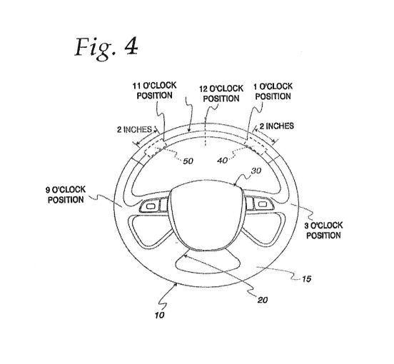
positions, respectively. As shown in Fla 4, one preferred size and location
for actuators 40, 50
is an are-segment-length of 2 inches with actuators 40, 50 covering a portion
of annular ring 15
of steering wheel 10 ending at about the 1 o'clock and II o'clock. positions
respectively such that
actuator 50 extends counterclockwise towards the 9 o'clock position and
actuator 40 extends
clockwise towards the 3 o'clock position.
100601 Actuators 40, 50 of the present invention may be membrane switches of a
type
manufactured by Tapecon, Inc., Tapeeon Membrane Switch Division, Rochester,
N.Y,
Membrane switches, as is known in the art, may be manufactured in variety of
configurations
each of which are single pole, single throw switches which are normally open.
Membrane
switch configurations include a standard membrane switch construction, a
tactile plastic dome
construction and a stainless steel dome construction. FIG. 5 illustrates one
type of membrane
switch 41 which includes top overlay 42, adhesive layer 43, top circuit 44,
circuit spacer 45,
bottom circuit 46, bottom overlay 47 and contacts 48. Membrane switch 41 is
normally open.
When top overlay 42 is depressed, top circuit 44 is flexed so that a circuit
is completed at
contacts 48. Depending on the arc-segment-length, as described above,
actuators 40, 50 may
each include one or more membrane switches. Membrane switch arrays, which
cover a larger
area than a single membrane switch, are taught, for example, in W01995001302,
titled "Curve-
conforming Sensor Array Pad." Actuators 40, 50 may be a fiber optic pressure
sensor, or an
array of fiber optic pressure sensors, of the type manufactured by Luna
Innovations, Blacksburg,
.Va. Alternatively, actuators 40, 50 may be a large-area flexible pressure
sensor matrix of the
type developed by the Quantum-Phase Electronics Center, School of Engineering,
University of
Tokyo, Tokyo, Japan and described in "A Large-Area, Flexible Pressure Sensor
Matrix With
Organic Field-Effect Transistors For Artificial Skin Applications," T. Someya
et al., PNAS, vol.
101, no. 27, Jul. 6, 2004. Furthermore, actuators 40, 50 may be a flexible
strain gage of a type
available from Omega Engineering, Inc., Stamford, Conn,
[0061] The actuators 40, 50 may be mechanically bonded to the steering wheel,
such as by
thermal or sonic welding if the materials of construction of the actuators 40,
50 and the steering
14
CA 02923130 2016-03-03
WO 2015/041864 PCT/US2014/054204
wheel 10 are compatible and susceptible to such attachment. The actuators 40,
50 may be
attached to the steering wheel 10 using an adhesive. The actuators 40, 50 when
attached to the
steering wheel 10 may he covered by a cover or skin (not shown) so that the
actuators 40, 50
reside under the skin of the steering wheel 10. Actuators 40, 50 can be
positioned under the skin
of the steering wheel 10 so as to make the actuators 40, 50 undetectable by
the human eye. The
actuators 40, 50 may he molded into the steering wheel 10 during the process
of manufacturing
the steering wheel 10. When molded into the steering wheel 10, the actuators
may be positioned
under the surface of the steering wheel 10 if the material of construction of
the steering wheel 10
is sufficiently deformable to permit deforming the steering wheel 10 in a
manner that also allows
activating the actuators 40, 50.
[00621 The properties of the material of construction of a steering wheel 10
will be known to
those of ordinary skill in the art such that the permissible methods for
attachment of actuators 40,
50 to the steering wheel 10 will he also be understood. For example, it is
known in the art that
steering wheels may be molded from a pliable cross-linked vinyl chloride
polymer as taught in
U.S. Pat, No. 4,567,217 to Yamazaki et al. It is further understood in the art
that flexible
sensors, such as membrane switches, may be encapsulated in a molded part as
taught in U.S. Pat.
No. 5,762,853 to Harris et al. Also, insert molded membrane switches have been
used as
steering wheel hub-mounted horn switches as taught in ITS. Pat. No. 5,198,629
to Hayashi et al.
[00631 To accommodate different hand positions used by a driver during
operation of a vehicle,
actuators 40, 50 may be configured to sense when the thumb of a hand is
pressing one or both of
the actuators 40, 50. FIG, 6 illustrates one design in which each of actuators
40, 50 are made up
of switch arrays 140, 150, respectively, and where the switch arrays 140, 150
each include a
plurality of switches 160. The switch array 140, 150 of FIG. 6 is merely
illustrative and does not
depict a necessary configuration of switches 160. The switches 160 are
normally open (off),
closed when depressed or selected (on), and return to open (off) when
deselected. Each of
switches 160 is connected to a controller 60 so that controller 60 may sense
when a switch 160 is
in the open position or the closed position. Switches 160 may be connected to
controller 60 via a
wiring harness (not shown) for example, such that each switch 160 is wired to
a terminal block
(not shown) and the terminal block is wired to the controller 60 via the
wiring harness. Those of
ordinary skill in the art will recognize other connection means for wiring
switches 160 to
controller 60. The activation state of each switch 160 in switch arrays 140,
150, that is to say
CA 02923130 2016-03-03
WO 2015/041864 PCT/US2014/054204
whether a switch 160 is on or off, may be determined by the controller 60, In
a typical operation,
a switch 160 opens and closes an electrical circuit between the switch 160 and
the controller 60.
If only switches 160 corresponding to a thumb-sized pattern are depressed,
then the actuators 40,
50 will be recognized as being in the "on" position by the controller 60.
However, if switches
160 corresponding to a pattern larger than a thumb are depressed, then
actuators 40, 50 will be
recognized as being in the "off position.
[0064] in the embodiments of the present invention which incorporate actuators
40, 50 as
illustrated in FIG. 6, the controller 60 is programmed to determine when
switches 160 are
depressed in a thumb-sized pattern. As used herein, a thumb-sized pattern
means an area that
ranges from about 0.5 square inches to about 2.25 square inches. Thus, if a
full four-fingered
grip is taken of steering wheel 10 a pattern of switches 160 may be depressed,
depending on
where the driver places his or her hand on the steering wheel, which exceeds
the size of the
pattern of switches made when a thumb depresses one of actuators 40, 50. Under
this condition,
controller 60 does not activate actuators 40, 50 and controller 60 recognizes
actuators 40, 50 as
being in the "off' position, However, if a thumb is then placed on either
actuator 40 or actuator
50, controller 60 registers that a thumb-sized pattern of switches has been
depressed and
controller 60 recognizes either actuator 40 or actuator 50, respectively, as
being in the on
position. Once actuators 40, 50 are activated via controller 60, either
actuator 40 or actuator 50
may, be depressed to turn on the corresponding signal lights (not shown) or
operate the
corresponding vehicle equipment component or function, such as a radio,
compact disc player,
cellular telephone or navigation system (not shown). Once activated,
simultaneously pressing
actuator 40 and actuator 50 will not turn on the corresponding turn signal
lights. If controller 60
has not activated actuators 40, 50, then depressing either actuator 40 or
actuator 50 will not turn
on the corresponding turn signal lights or operate the corresponding vehicle
function. It will be
understood by those of ordinary skill in the art that a motor vehicle
equipment component will
have at least one function, being turned on/off for example, but may also have
a plurality of
functions,
[0065] In one embodiment, pressing an activated actuator 40 or an activated
actuator 50 will
turn on an audible signal in addition to turning on the corresponding turn
signal lights or
equipment component. The audible signal may serve to indicate to the driver
that the turn signal
has been turned on. The audible signal may also serve to indicate that the
actuators 40, 50 have
16
CA 02923130 2016-03-03
WO 2015/041864 PCT/US2014/054204
become activated. In one embodiment, the audible signal may emanate from the
speaker system
of the motor vehicle that is used, for example, to signal that a car door is
open when the ignition
key remains in the ignition switch. In another embodiment, the audible signal
may emanate from
the same sound source used to alert a driver of the motor vehicle that the
stalk-switch-operated
turn signal has been turned on. In another embodiment, the audible signal may
be wirelessly
broadcast using BLUETOOTH technology such that the audible signal is received
in an ear piece
or headset worn by the driver and the driver thereby hears the audible signal.
In yet another
embodiment, actuators 40, 50 may be connected to corresponding turn signal
indicator lights
located in the dashboard of the motor vehicle such that pressing an activated
actuator 40 or an
activated actuator 50 will light the corresponding turn signal indicator
lights. BLUETOOTH
technology or, alternatively BLUETOOTH system refers to a proprietary open
wireless
technology standard for exchanging data over short distances (using short-
wavelength radio
transmissions in the ISM band from 2400-2480 MHz) from fixed and mobile
devices, creating
personal area networks with high levels of security. BLUETOOTH technology and
systems are
available from Bluetooth Sin, inn, Lake Washington Boulevard, Kirkland, Wash.
[0066] FIG. 7 illustrates a steering wheel 110 of the prior art and FIGS. 8a-
8d illustrate a
driver's hands gripping the steering wheel 110 of FIG, 7. In FIG. 7, hot
buttons 115, 120 are
depicted positioned on the steering wheel 110 as described in the prior art.
As used herein, the
term "hot button" refers to a single on/off switch which is pressed to turn on
and pressed again to
turn off Thus, hot buttons 115, 120 are placed at the 10 o'clock and 2 o'clock
positions on the
steering wheel 110, respectively. Referring to FIG. 8a, it is clear that the
four-fingered grip of the
driver must he loosened, thus not fully gripping steering 110, in order to
rotate the thumb into
position to depress hot button 115. In FIG. 8b, the driver must again modify
the four-fingered
grip to accommodate the spoke 125 in order to access and depress hot button
115, In FIG, Sc, it
is again clear that the four-fingered grip of the driver must be loosened,
thus not fully gripping
steering 110, in order to rotate the thumb into position to depress hot button
120. As was seen in
FIG. 8b, FIG. 8d illustrates how the driver must modify the four-fingered grip
to accommodate
the spoke 125 in order to access and depress hot button 120.
[00671 In one embodiment, actuators 40, 50 are preferably positioned on
annular ring 15 of
steering wheel 10 facing the driver. When positioned in this location,
actuators 40, 50 may be
activated when the driver presses down on the steering wheel using a thumb of
the driver's left or
17
CA 02923130 2016-03-03
WO 2015/041864 PCT/US2014/054204
right hands. FIGS. 9a-9d illustrate a driver gripping annular ring 15 of
steering wheel 10 with
the driver's thumb position in a full four-fingered grip (FIGS. 9b and 9e) and
with the thumb
positioned over actuators 40, 50 (FIGS. 9a and 96). It will be recognized by
persons of ordinary
skill in the art that actuators 40, 50 may be positioned in locations other
than on the side of
annular ring 15 directly facing the driver.
[0068] Referring now to FIG. 10 which illustrates an embodiment of the present
invention,
actuators 40, 50 are connected to controller 60. Controller 60 includes
processor 70. Processor
70 includes logic circuits 80, timer 90 and memory 100. Controller 60 is
connected to right-side
signal circuit 145 and left-side signal circuit 155. Right-side signal circuit
145 includes right-side
signal lights (not shown) and left-side signal circuit (155) includes left-
side signal lights (not
shown). Turn signal stalk switch (not shown) may also be connected to
controller 60.
Alternately, as further described herein below, actuators 40, 50 and
controller 60 may be used
with other motor vehicle equipment or systems to operate an equipment
component or to allow
actuators 40, 50 to function as thumb shifters.
[0069] In an embodiment of the present invention, controller 60 controls the
operation of
actuators 40, 50 such that when actuator 40 is depressed, right side signal
tights (not shown) of
right-side signal circuit 145 are energized and when actuator 50 is depressed,
left-side signal
lights (not shown) of left-side signal circuit 155) are energized. When
energized, right-side
signal lights and/or left-side signal lights (not shown) may "blink" as is
common to all turn
signals.
[0070] FIG. 11 illustrates the circuit logic of one embodiment of the present
invention. In this
embodiment, when actuator 40 is depressed it is in a closed position and it
completes a circuit to
controller 60. Similarly, when actuator 50 is depressed it completes a circuit
to controller 60. If
both actuator 40 and actuator 50 are depressed, controller 60 via timer 90
(shown in FIG, 10)
measures the time each of actuator 40 and actuator 50 is depressed. If the
measured time
exceeds a pre-set threshold time, I second for example, then controller 60
activates actuators 40,
50. If the measured time is less than the pre-set threshold time, controller
60 does not activate
actuators 40, 50. The pre-set threshold time can be varied and programmed into
memory 100
shown in FIG. 10 such that logic circuits 80 of FIG. 10 in controller 60
activate actuators 40, 50.
The pre-set threshold time may range from about 0,5 seconds to about 5
seconds. It is preferred
18
CA 02923130 2016-03-03
WO 2015/041864 PCT/US2014/054204
that the pre-set threshold time be about 1 second. When activated, depressing
actuator 40 results
in the right side signal lights (not shown) of right-side signal circuit 145
to be energized and
when actuator 50 is depressed left-side signal lights (not shown) of left-side
signal circuit 155)
are energized. When energized, right-side signal lamp and/or left-side signal
lamp (not shown)
may "blink as is common to all turn signals.
[0071] FIG. 12 (FIGS, 12a and 12b inclusive) illustrates the logic circuit of
a further
embodiment of the present invention in which actuators 40, 50 are of the type
illustrated in FIG,
6. In this embodiment, actuator 40 and actuator 50 are each made up of switch
arrays 140, 150,
respectively, where each switch array 140, 150 includes a plurality of
switches 160. The
switches 160 are normally open (off), closed when depressed or selected (on),
and return to open
(off) when deselected. Each of switches 160 is connected to a controller 60 so
that controller 60
may sense when a switch 160 is in the open position or the closed position. in
a typical
operation, a switch 160 opens and closes an electrical circuit between the
switch 160 and the
controller 60. If only switches 160 corresponding to a thumb pattern are
depressed, then the
actuators 40, 50 will be recognized as being on by the controller 60, However,
if switches 160
corresponding to a pattern larger than a thumb-sized pattern are depressed,
then actuators 40, 50
will be recognized as being "off" The controller 60 is programmed to determine
when switches
160 are depressed in a thumb-sized pattern. Thus, if a full four-fingered grip
is taken of steering
wheel 10 a pattern of switches 160 may be depressed, depending on where the
driver places his
or her hand on the steering wheel, which exceeds the size of the thumb-sized
pattern made when
a thumb depresses actuators 40, 50. Under this condition, controller 60 does
not activate
actuators 40, 50 and controller 60 recognizes actuators 40, 50 as being in the
"off' position,
However, if a thumb is then placed on actuators 40, 50, controller 60
registers that a thumb-sized
pattern of switches has been depressed and controller 60 will activate the
actuators 40, 50 if they
are depressed for at least the pre-set threshold time. When controller 60
activates actuators 40,
50, either one of actuator 40 or actuator 50 may be depressed to turn on the
corresponding signal
lights (not show-n), or to operate a motor vehicle equipment component, as
described herein
below, or to operate as a thumb shifter, as also described herein below. If
controller 60 has not
activated actuators 40, 50, then depressing either of actuator 40 or actuator
50 will not turn on
the corresponding signal lights, operate as an equipment component, or act as
a thumb shifter.
CA 02923130 2016-03-03
WO 2015/041864
PCT/US2014/054204
[0072] To deactivate actuators 40, 50, both actuator 40 and actuator 50 are
depressed
simultaneously and held for a pre-set threshold time. Referring to FIG. 10,
timer 90 of controller
60 measures the time each of actuator 40 and actuator 50 is depressed. If the
measured time
exceeds a pre-set threshold time, I second for example, then controller 60
deactivates the
activated actuators 40, 50, If the measured time is less than the pre-set
threshold time, controller
60 does not deactivate actuators 40, 50. The pre-set threshold time can be
varied and
programmed into memory 100 shown in FIG. 10 such that logic circuits 80 of
FIG. 10 in
controller 60 deactivate activated actuators 40, 50. It is preferred that the
pre-set threshold time
be about 1 second. When actuators 40, 50 are deactivated, depressing actuators
40, 50 will not
turn on the corresponding turn signal lights, equipment component or function
as paddle shifters.
[0073] When driving a motor vehicle equipped with a steering wheel that
incorporates the
present invention, a driver may use the vehicle's stalk switch to turn on the
vehicle's turn signals.
Preferably the operation of the stalk switch is not modified by incorporation
of the present
invention into the steering wheel, but modifications may be made without
altering the concepts
encompassed by the descriptions herein. The actuators 40, 50 may be used to
turn on and turn
off the turn signals of the motor vehicle once the controller 60 has activated
actuators 40, 50 as
provided herein. Thus, in a preferred embodiment, the actuators 40, 50 operate
in parallel with
the vehicle's stalk switch and the turn signals turn on when activated
actuator 40 or activated
actuator 50 is depressed and turn off when activated actuator 40 or,
respectively, activated
actuator 50 is released. Unlike the conventional stalk switch, which turns off
when the steering
wheel is rotated away from the direction of the turn, in the preferred
embodiment of the present
invention the turn signals only operate when one of actuator 40 and actuator
50 is depressed. in
a critical or high-stress driving situation, a driver need only position his
or her thumbs on the
actuators 40, 50, depress both of the actuators 40, 50 and maintain them in an
"on" position for a
pre-determined amount of time, and thereafter operate the turn signals using
only one of the
actuators 40, 50. With the system and apparatus of the present invention, a
turn signal cannot
prematurely or accidently turn off. Once the actuators 40, 50 are activated, a
turn signal is turned
on by depressing one of actuators 40, 50 and it is turned off by releasing the
depressed actuator.
[0074] In a further embodiment, which employs actuators 40 and 50 of the
present invention as
illustrated in FIG. 11, two activation settings for actuators 40 and 50 are
possible: (1) actuators
40 and 50 require actuator activation upon each start up of the motor vehicle,
or (2) actuators 40
CA 02923130 2016-03-03
WO 2015/041864 PCT/US2014/054204
and 50 are always activated when the engine of the motor vehicle is turned on
after having once
been activated. Controller 60 in this embodiment is a programmable controller
or, alternatively,
a computer-implemented device, which allows for the programming of actuators
40 and 50 with
respect to their on/off status. Thus, if both actuator 40 and actuator 50 are
depressed, controller
60 via timer 90 (shown in FIG, 10) measures the time each of actuator 40 and
actuator 50 is
depressed. Controller 60 may be pre-programmed with two threshold time ranges,
for example a
first threshold time range and a second threshold time range, such that
simultaneously depressing
actuators 40 and 50 for a time within the first threshold time range, for
example 1 to 2 seconds,
activates actuators 40 and 50 only for the period of time the engine of the
motor vehicle is turned
on. It should be noted that those of ordinary skill in the art will understand
that the first
threshold time range may be as short as a fraction of a second such that
actuators 40, 50 are
activated rapidly. Furthermore, those of ordinary skill in the art will
understand that any
threshold time range implemented with respect to embodiments of the present
invention may be
varied to suit specific needs and uses. In such instance, actuators 40 and 50
would need to be
activated as described each time the motor vehicle is turned on. However, if
actuators 40 and 50
are simultaneously depressed and held through the first threshold time range
and for a duration
within the second threshold time range, 3 to 5 seconds tbr example, actuators
40 and 50 are
always on in that they are always activated when the engine of the motor
vehicle is turned on. if
the measured time is within either the first or second threshold time range,
then controller 60
activates actuators 40, 50. If the measured time is less than the first
threshold time range,
controller 60 does not activate actuators 40, 50. The pre-set threshold time
ranges can be varied
and programmed into memory 100 shown in FIG. 10 such that logic circuits 80 of
FIG. 10 in
controller 60 activate actuators 40, 50. The pre-set threshold time ranges may
range from about
0.5 seconds to about 5 seconds, it is preferred that the first pre-set
threshold time range be about
I to 2 seconds and that the second pre-set threshold time range be about 3 to
5 seconds. When
activated, depressing actuator 40 results in the right side signal lights (not
shown) of right-side
signal circuit 145 to be energized and when actuator 50 is depressed left-side
signal lights (not
shown) of left-side signal circuit 155) are energized. When energized, right-
side signal lamp
and/or left-side signal lamp (not shown) may "blink" as is common to all turn
signals.
21
CA 02923130 2016-03-03
WO 2015/041864
PCT/US2014/054204
ACTUATOR SETTINGS: AUTONOMOUS AND MANUAL ENGAGED SETTINGS
[0075] in one embodiment, once actuators 40, 50 are activated, at least two
engaged settings of
actuators 40, 50 are possible: (I) autonomous engagement, and (2) manual
engagement. The
controller 60 in this embodiment is a programmable controller which allows for
the
programming of actuators with respect to this engagement status.
[0076] In an embodiment, an autonomous engaged setting is achieved when an
actuator 40, 50 is
depressed and released within a short preset duration. In a preferred
embodiment, this preset
duration should be no longer than what is approximately required for a driver
to press a thumb
on the steering wheel actuator 40, 50 and release. This duration may be
approximately 0,5
seconds, or another duration programmed by a driver to their preference to
achieve this
objective. When an actuator 40, 50 is pressed and released within this
duration the actuator 40,
50 will remain autonomously engaged and the corresponding exterior signal
light will continue
to flash. If an actuator 40, 50 is pressed for a duration exceeding the preset
duration, the actuator
40, 50 becomes manually engaged, and will remain on while being pressed by the
driver, and
will go off when released by the driver,
[00771 In an embodiment of the present invention, if for example an actuator
40 has been
autonomously engaged, it will be disengaged if the opposite actuator 50 is
pressed for any length
of time. In a further embodiment, if an actuator 40, 50 has been autonomously
engaged, it will be
disengaged if the same actuator is pressed and released within a short preset
duration. Such a
short preset duration may be the same preset duration required to autonomously
engage the
actuator, or another duration programmed by the driver to achieve this
objective,
SELF-CANCELATION AND DISENGAGEMENT OF AN AUTONOMOUSLY ENGAGED
ACTUATOR SETTING VIA LANE POSITION DETECTION SYSTEMS
[0078] Lane Position Detection and Warning Systems ("LPDWS") are known for use
on motor
vehicles and are often used to detect a vehicle's relative position within a
lane and path on a
roadway. Such systems may use video sensors, laser sensors and infrared
sensors among other
sensors, to assess the roadway and, depending on the road condition, lane
position, or perceived
hazard, may alert a driver with audio, visual or tactile stimuli such as seat
or steering wheel
22
CA 02923130 2016-03-03
WO 2015/041864 PCT/US2014/054204
vibrations, to awaken a drowsy driver, correct driving path, or justify the
vehicle within the lines
of a lane.
[0079] One such system is Ford Motor Company's "Lane Keeping System" which
uses a
forward-facing digital camera mounted behind the windshield inside the
rearview mirror to
detect unintended lane departures. This system presents three levels of
assistance; "Lane
Keeping Alert", "Lane Keeping Aid" and "Driver Alert", which are activated
based on driver
preference, behavior, and the degree of the lane departure. When this system
detects that the car
is approaching the edge of a lane without a turn signal activated, a yellow
lane marker alert
displays on the dash and the steering wheel vibrates, if the driver fails to
respond to such alerts
and continues to depart the lane, the yellow lane marker alert turns red and
the system provides
steering torque to rotate the steering wheel and the vehicle back. toward the
center of the lane.
The "Driver Alert" monitors the vehicle's movements within the lane markings
and will sound
alerts if a driving pattern detected is consistent with a drowsy driver.
[00801 Ford's rearview mirror assembly for use with its Lane Keeping System is
produced by
GENTEX Corporation with technology developed by MOBILEYE NV, of Amstelveen,
Netherlands. Some of Mobileye's lane departure and warning systems use vision-
based forward-
looking technology and algorithms to interpret video images to estimate
vehicle roadway lane
alignment.
[0081] Other automakers have incorporated Mobileye's technology into similar
Lane Position
Detection systems. BMW has incorporated Mobileye's technology into its Lane
Departure
Warning System, Mobileye and TRW have partnered to provide camera-based
systems tbr
Chrysler, JEEP, GM and Hyundai. Mobileye and Delphi have partnered to provide
similar
systems for Volvo. Mobileye and Leopold Kostal have partnered to provide
similar systems for
PSA Peugeot Citroen. Mobilieye and Magna Electronics have partnered to provide
similar
systems for Honda and Opel, among other partnerships.
[00821 Denso Corporation of Japan and Toyota have developed a "Lane Keeping
Assist
System" which uses a forward-facing stereo camera to detect the shapes and
positions of lane
markers. This system transmits data from the vision sensor to a steering
assist electronic control
unit ("ECU") which determines if the vehicle is straying from its lane. If an
unintended lane
deviation is detected, the ECU alerts the driver with visual and auditory
alerts. The ECU may
23
CA 02923130 2016-03-03
WO 2015/041864 PCT/US2014/054204
also send a steering torque signal to the electric power steering ("EPS")
controller to apply a
slight counter-steering torque to realign the vehicle within the lane.
[0083] BOSCH of Germany has developed a Multi Purpose Camera ("MPC") for use
in video-
based driver assistance systems such as LPDWS. Bosch's MPC is an integrated
unit which
contains its own microprocessor and does not require a separate control unit.
[0084] A cornerstone characteristic of the systems developed by Mobileye,
Denso, Bosch and
other similar systems under different brand names offered by different
technology companies
and automobile manufacturers, are the systems' ability to continuously assess
the vehicle's
relative position within the lines of a lane and communicate such information
to various
accessory components.
[0085] in a preferred embodiment, this Turn Signal Safety System ("TSSS") uses
the lane
position information obtained from such a lane position detection type system
("LPDS") to self-
cancel an autonomously engaged turn signal actuator 40, 50 and corresponding
exterior signal
light after a lane change has been detected. In a preferred embodiment, the
LPDS is interfaced
with this TSSS so that the two systems my communicate information. In such an
embodiment,
once a turn signal has been autonomously engaged, the controller 60 will
"disengage" an
autonomously engaged turn signal when the LPDS has detected that the vehicle
has fully exited
one lane and fully entered a "new" lane and is driving approximately justified
within that lane.
[0086] After the system detects that a vehicle has exited one lane and entered
a new lane, the
system may determine that a vehicle is driving justified within the lines of a
new lane if the
vehicle maintains a driving path within the lines of a new lane for a minimum
preset duration of
time. Such duration may he approximately 1-2 seconds, or a few seconds, or
another
programmable duration of time sufficient to determine that the vehicle has
entered the desired
new lane and the desired lane change has been completed.
[0087] In another embodiment, once a turn signal has been autonomously engaged
and the
LPDS has detected that the vehicle has exited one lane and entered another
lane, the controller
60 will not disengage an autonomously engaged turn signal if the LPDS detects
that the vehicle
is continuing to turn in the same direction as the autonomously engaged
actuator 40, 50, Such an
autonomously engaged actuator 40, 50 will disengage when the system has
determined that the
24
CA 02923130 2016-03-03
WO 2015/041864 PCT/US2014/054204
vehicle has entered a new lane and is driving approximately ,lustified within
the lane for a preset
duration as described,
SELF-CANCELATION AND DISENGAGEMENT OF AN AUTONOMOUSLY ENGAGED
ACTUATOR SETTING VIA STEERING WHEEL ROTATION, TORQUE AND ANGLE
DETECTION S YS'17EMS
[0088] Systems for determining the rotation and angle of a steering wheel have
been used for
many years in various systems including Power Steering Systems ("PSS"). One
example of a
PSS which incorporates a steering wheel angle sensor is Ford's Electric Power-
Assisted Steering
("EPAS"). Ford's EPAS system provides greater or reduced steering wheel
rotation assistance to
a driver based on vehicle speed, road conditions and the degree of angle
rotation of the steering
wheel. This system generally provides more assistance at lower speed and less
assistance at
higher speed. This makes parking more effortless and highway driving more
controllable. Such
systems generally include a controller among other components.
[00891 Other systems which use steering wheel angle sensors include "Active
Steering
Systems". Such systems adjust the degree of steering wheel rotation and angle
required for turns
based on the speed of the vehicle. For example, AUDI and BMW provide similar
systems which
alter the steering ratio based on the speed of the vehicle in the following
manner: at a low speed,
such as parking, a slight turn of the wheel creates a greater degree of
driving wheel directional
change. At a higher speed, a comparable degree of steering wheel turn creates
a lesser degree of
driving wheel directional change to provide maximum control over the vehicle.
[00901 Steering Wheel Angle Sensors ("SWAS") are also used in on-board
stability-control
systems ("SCS") such as BMW's "Dynamic Stability Control System" ("DSC") which
maintains
a vehicle's intended course in the event of a driver's inadvertent under- or
over-steers, or on
surfaces where some or all of the wheels have different levels of traction,
Such systems
generally include a controller among other components.
[0091] BMW Dynamic Stability system is a type of Electronic Stability Control
system ("ESC")
which is now mandatory on new cars in the United States and many countries
worldwide.
Generally, when an ESC system detects a probable loss of steering control, the
system estimates
CA 02923130 2016-03-03
WO 2015/041864 PCT/US2014/054204
the direction of the skid and then applies breaking to individual wheels to
counter the skid and
bring the vehicle back in line with the driver's intended path.
[0092] ESC system determines a driver's intended path by assessing data
received from a
steering wheel angle sensor, which constantly monitors the steering wheel
position and outputs
the information to the ESC electronic control unit. ("ECU"). The ESC
determines a vehicle's
actual direction by data output received to its ECU from multiple sensors and
systems which
include the anti-lock breaking system ("ABS"), individual wheel speed sensors,
lateral
acceleration sensors and vehicle rotation sensors (YAW).
[0093] The ESC is connected with these various sensors and systems via a
Controller Area
Network ("CAN" bus) interface which permits their communication. Once the ESC
has
determined a driver's intended path and compared it against the vehicle's
actual position, if the
ESC determines that the vehicle is in a skid, it may send commands to
connected systems such
as the ABS to apply breaking to individual wheels to correct the vehicle path.
Some ESC
systems are also capable of reducing engine throttle amounts until vehicle
control is regained. in
many vehicles, an ESC system will inform the driver if it has intervened with
a dashboard light
and/or tone.
[0094] Various steering wheel rotation and angle detection systems are often
comprised of
sensors and components specifically designed to assess steering wheel torque,
rotation and angle.
One such sensor for use in automobiles has been developed by Bourns, Inc. of
Riverside,
California, which manufactures a combined steering torque and angle sensor for
use with
Electric Power Assisted Steering applications and ESC. Bourns' combined sensor
may be used
in both steering column and steering rack mounted ERAS and provides CAN
steering sensor
output
[0095] Another such steering wheel position sensor for use in automobiles has
been developed
by Bosch of Germany. The Bosch model LWS6 Steering-Angle Sensor uses Hall
Effect
technology to detect magnetic field changes in a multi-pole magnet affixed to
the steering
column. This sensor translates magnetic -field changes into square-wave
signals which are
transmitted to the control unit to derive the position, rotation direction,
and rotation speed of the
steering wheel.
26
CA 02923130 2016-03-03
WO 2015/041864 PCT/US2014/054204
[0096] in an embodiment of the present invention, this Steering Wheel TSSS may
be interfaced
with a steering wheel rotation and angle detection sensor or system such as
those described and
others with similar capabilities, so that an autonomously engaged turn signal
actuator 40, 50 may
be disengaged when certain steering wheel rotation and/or steering wheel angle
changes or
patterns are detected. In such an embodiment, an actuator 40, 50 may be
autonomously engaged
by a driver at any degree of steering wheel 10 rotation and subsequently
disengaged in various
ways. For example, an actuator 40, 50 may be autonomously engaged by a driver
when the
steering wheel 10 is turned Left, Center or Right.
[0097] When a motor vehicle that has been modified to include the system and
apparatus of the
present invention, the following example illustrates adaptations of the
present invention in which
actuators 40, 50 are activated and a steering wheel angle and rotation sensor
system is used to
disengage an autonomously engaged turn signal actuator 40, 50:
1) An actuator 40, 50 is autonomously engaged providing an
autonomously energized exterior signal light.
2) The steering wheel rotation and angle sensor system determines
the rotation and angle of the steering wheel 10 at the moment the
actuator 40, 50 is engaged.
3) If the actuator 40, 50 is engaged when the steering wheel 10 is at
approximately center, the signal will disengage after the steering wheel
is turned to a minimum preset degree of angle in the same direction
of the engaged actuator 40, 50 and then returned to approximate
center. For example, if the steering wheel 10 is approximately center
when the right actuator 40 is engaged, the steering wheel 10 must first
rotate to a minimum preset angle to the right, and must subsequently
be rotated to approximately center for the autonomously engaged
actuator 40 to disengage. Such minimum preset degree of angle may
be approximately 45 degrees.
4) If the actuator 40, 50 is engaged when the steering wheel 10 is
rotated to a minimum preset degree of angle other than approximately
center, and the direction of the actuator 40, 50 and the rotation of the
steering wheel 10 are both in the same direction, the signal will
CA 02923130 2016-03-03
WO 2015/041864 PCT/US2014/054204
disengage when the steering wheel 10 reaches the center position. For
example, if the steering wheel 10 is rotated to a minimum preset
degree of angle to the left when the left actuator 50 is engaged, the
autonomously engaged actuator 50 will disengage when the steering
wheel 10 is rotated to approximately center, Such minimum preset
degree of angle may he approximately 45 degrees.
5) If the actuator 40, 50 is engaged when the steering wheel 10 is
rotated to a minimum preset degree of angle other than approximately
center, and the direction of the actuator 40, 50 and the rotation of the
steering wheel 10 are in opposite directions, the signal will disengage
when the steering wheel 10 has been rotated to a preset minimum
degree of angle in the direction of the actuator 40, 50 past center and
subsequently returned to center. For example, if the steering wheel 10
is turned to a minimum preset degree of angle to the right when the
left actuator 50 is autonomously engaged, the autonomously engaged
actuator 50 will disengage when the steering wheel 10 is first turned to
a minimum degree of angle to the left and subsequently rotated to
center. Such minimum preset degree of angle may be approximately
45 degrees.
[0098-] Although it is understood that the steering wheel 10 center position
is generally
considered to represent a specific angle, degree of rotation, or position, an
approximately center
position provides a range including a specific center location and locations
offset from center.
For example, if center is deemed to be both 0 and 360 degrees, an
approximately center range
may provide a range from 350 to 10 degrees, or 355 to 5 degrees, or may
include a range that is a
specific fixed point such as 360 and 0 degrees, or another range,
100991 The minimum preset angle of rotation described could be approximately
45 degrees, or
another degree of angle which is sufficient to differentiate such an angle
from an approximately
center position,
[00100] in an embodiment in which the present invention is interlaced with a
system capable of
monitoring both the angle of the steering wheel 10 and the speed of the
vehicle, such as an ESC
28
CA 02923130 2016-03-03
WO 2015/041864
PCT/US2014/054204
system, the minimum preset angle of steering wheel rotation sufficient to
differentiate such an
angle from an approximately center position, for the purposes of registering
that a turn has
occurred, may be varied based on the speed of the vehicle. For example, the
TSSS controller
may be programmed to require a greater angle of steering wheel 10 rotation at
lower speed,
where many vehicles may be required to turn around corners of city blocks, and
a lesser angle of
steering wheel 10 rotation at higher speeds where such an angle may not be
required for highway
lane changes or for safe turns. The objective of such a configuration is to
reduce instances in
which an autonomously engaged turn signal fails to cancel after a turn or lane
change has been
completed.
[00101-1 Automobile manufacturers such as NISSAN have developed systems
commonly
referred to as "Steer-By-Wire" ("SBW"). SBW systems are generally considered
to be systems
which replace the mechanical control systems such as a steering rack or
steering column with
electronic signals, electromechanical actuators and other components. NISSAN's
SBW system
uses a steering three sensor connected to the steering wheel to determine the
driver's steering
angle, and adjusts the wheels accordingly to steer the car in the desired
direction,
[00102] In an embodiment of the present invention, this Steering Wheel TSSS
may be interfaced
with a SBW system and more specifically may be interfaced with the SBW-
controller or
electronic control unit so that steering wheel angle and rotation data
collected by the SBW
system may be communicated to this Steering Wheel TSSS so that an autonomously
engaged
turn signal actuator may be disengaged when certain steering wheel rotation
and/or steering
wheel angle changes or patterns are detected.
[00103] When a motor vehicle that has been modified to include the system and
apparatus of the
present invention, the following example illustrates adaptations of the
present invention in which
actuators 40, 50 are activated and a SBW system which calculates steering
wheel 10 angle and
rotation is used to disengage an autonomously engaged turn signal actuator 40,
50:
1) An actuator 40, 50 is autonomously engaged providing an
autonomously energized exterior signal light.
2) A SBW system determines the rotation and angle of the steering
wheel 10 at the moment the actuator 40, 50 is engaged.
3) If the actuator 40, 50 is engaged when the steering wheel 10 is at
29
CA 02923130 2016-03-03
WO 2015/041864
PCT/US2014/054204
approximately center, the signal will disengage after the steering wheel 10
is turned to a minimum preset degree of angle in the same direction of the
engaged actuator 40, 50 and then returned to approximate center. For
example, if the steering wheel 10 is approximately center when the right
actuator 40 is engaged, the steering wheel 10 must first rotate to a
minimum preset angle. to the right, and must subsequently be rotated to
approximately center for the autonomously engaged actuator 40 to
disengage. Such minimum preset degree of angle may be approximately
45 degrees.
4) if the actuator 40, 50 is engaged when the steering wheel 10 is
rotated to a minimum preset degree of angle other than approximately
center, and the direction of the actuator 40, 50 and the rotation of the
steering wheel 10 are both in the same direction, the signal will disengage
when the steering wheel 10 reaches the center position. For example, if
the steering wheel 10 is rotated to a minimum preset degree of angle to the
left when the left actuator 50 is engaged, the autonomously engaged
actuator 50 will disengage when the steering wheel 10 is rotated to
approximately center. Such minimum preset degree of angle may be
approximately 45 degrees.
5) if the actuator 40, 50 is engaged when the steering wheel 10 is
rotated to a minimum preset degree of angle other than approximately
center, and the direction of the actuator 40, 50 and the rotation of the
steering wheel 10 are in opposite directions, the signal will disengage
when the steering wheel 10 has been rotated to a preset minimum degree
of angle in the direction of the actuator 40, 50 past center and
subsequently returned to center. For example, if the steering wheel 10 is
turned to a minimum preset degree of angle to the right when the left
actuator 50 is autonomously engaged, the autonomously engaged actuator
50 will disengage when the steering wheel 10 is first turned to a minimum
degree of angle to the left and subsequently rotated to center. Such
minimum preset degree of angle may be approximately 45 degrees.
CA 02923130 2016-03-03
WO 2015/041864 PCT/US2014/054204
[001041 The minimum preset angle of rotation described could be approximately
45 degrees, or
another degree of angle which is sufficient to differentiate such an angle
from an approximately
center position.
nterfac in,gnm it h a Lane . POO- ioppetec tion..System.
[00105] Embodiments of the present invention provide an interface between the
turn signal
systems of the present invention and lane detection systems to disengage an
autonomously
engaged turn signal in turns which do not result in a lane change. Many
turning situations which
require a driver to signal an intended turn do not always result in a lane
change, fur instance,
exiting a highway. Highway exits and entrances, among other situations in
which a driver
executes a turn without changing a lane, are also frequently situations in
which the degree of
steering wheel angle rotation required for the turn is insufficient to cancel
an engaged turn signal
lever once the steering wheel is returned to center. Many roadway exits and
entrances follow a
gradual corkscrew, semi-corkscrew, curved, or diagonal type path designed with
a very slight
turning angle so as to provide a driver with the safest and least abrupt
transition from one
roadway to the next.
[00106] These situations also highlight a shortcoming in the functionality of
the traditional turn
signal lever. Specifically, the slight turn angle is often insufficient to
cancel an engaged turn
signal once the steering wheel has been returned to center, This scenario
precipitates a common
hazard when a vehicle's turn signal remains on after it is needed whereby
transmitting inaccurate
information to other drivers. These situations also require a driver to remove
his/her hand from
the steering wheel, or alter their grip, to cancel the on-going signal. This
requirement again
detracts from the optimal control achieved by driving with two hands on the
steering wheel. It is
therefore important to provide a system for disengaging an autonomously
engaged turn signal by
detecting when a turn has been completed, even if such a turn does not result
in a lane change,
and in situations where the turning angle is very slight,
[00107] In an embodiment of the present invention, a LTD type system, which is
capable of
determining whether a roadway is straight or curved, is interfaced with this
turn signal system so
that the two systems may communicate information. In such an embodiment, once
a turn signal
has been autonomously engaged, the controller 60 will disengage an
autonomously engaged turn
3
CA 02923130 2016-03-03
WO 2015/041864 PCT/US2014/054204
signal when the LPD system has detected that the vehicle has completed a turn
even if no lane
change has occurred.
[00108] For example, if a turn signal is autonomously engaged when the LPD
system has
determined that the vehicle is driving approximately straight, the system will
disengage an
autonomously engaged turn signal after the LPD system detects that the vehicle
has turned in the
same direction of the turn signal to a certain degree and subsequently
returned to a straight
course for a preset duration.
[00109] In another example, if a turn signal is autonomously engaged when the
vehicle is
already driving in a turn, the system will disengage the turn signal after the
car has driven in the
same direction of the turn signal and returned to a straight driving course
for a preset duration.
[00110] In another example, if a turn signal is autonomously engaged in the
opposite direction
of the driving turn, the system will disengage the turn signal after the car
has turned in the
direction of the turn signal and subsequently returned to a straight driving
course for a preset
duration.
Interfacing with a Lane Departure Warning System
[00111] Embodiments of the present invention provide an interface between turn
signal systems
of the present invention and LPD and lane departure warning systems ("LEWS").
A benefit of
such an interface is to improve deficiencies incurred when such systems are
interfaced with the
traditional stalk-type turn signal lever. As described, LPD and LDWS are often
used to detect a
vehicle's relative position within a lane or path on a roadway, and are
further used to alert a
driver if an unintended deviation from a lane is detected. One apparently
common characteristic.
of such systems is that a lane deviation is deemed "unintended" or "intended"
depending upon
whether a driver has engaged a turn signal in advance of, or in some instances
during, a turn.
Generally, when a turn signal is engaged, LDWS enter a dormant state which
persists until the
turn signal is disengaged. In such a state the LDWS does not provide any
warnings, alerts or
corrective measures to the driver.
[00112] An apparent critical shortcoming of such LDWS is that they function at
the mercy of
the turn signal. Specifically, if a turn signal fails to cancel after a lane
change has been
completed, which is a common occurrence, the LDWS will remain dormant after it
is needed
32
CA 02923130 2016-03-03
WO 2015/041864 PCT/US2014/054204
once again to safely provide necessary warnings to drivers. The functionality
of the traditional
turn signal lever, and its well-known inexactitude and deficiencies, detract
from the full impact
of innovative safety enhancement systems such as LPD and LDWS.
[00113] it would therefore be beneficial to provide a turn signal system and
apparatus which,
when interfaced with a LDWS, will disengage an autonomously engaged turn
signal after a turn
or lane change has been detected so as to restore the safety functions of such
a LDWS at the
earliest possible interval, and to further avoid instances when a turn signal
remains inadvertently
engaged after a lane change or turn has been completed. The interface system
of the present
invention provides a remedy for the problems described by having the LDWS
disengage the turn
signal and thereby restore the LDWS to an active status at the earliest
possible moment after a
lane change has been detected.
[00114] The embodiments described herein offer non-limiting examples of how
the turn signal
system of the present invention may be interfaced with a LPD and LDWS to
disengage an
autonomously engaged turn signal of the present invention after a turn or lane
change has been
completed to provide a re-activated LDWS which is not subject to the
inexactitude of the
traditional turn signal lever.
Inte' çg wifir rn Wh661..Antik,' and/or Rotkaki# :Sens*: Ustemi
[00115] In further embodiments, the turn signal systems of the present
invention are
simultaneously interfaced with the LPD system and a steering wheel angle and
rotation sensor
system to disengage an autonomously engaged turn signal with the steering
wheel angle and
rotation sensor system if the LPD system fails to detect a lane change or
turn.
[00116] As described herein, an advantage of LPD systems and LDWS is to
provide safety
benefits and means for detecting a vehicle's position on the roadway. However,
such systems
are not infallible and may not always be able to determine if a lane has been
changed, or a turn
commenced or completed. LPD and LDWS typically determine a vehicle's lane
position based
on road markings. Road markings such as painted lane markings may vary to such
a degree that,
at times, such visual-based systems cannot accurately determine the boundaries
of a lane, For
example, a car could exit a lane with clear markings and enter a lane with
vague markings
possibly preventing the LPD system from accurately determining if a lane
change has been
executed, Such systems may also misread the roadway if confronted with various
types of
33
CA 02923130 2016-03-03
WO 2015/041864 PCT/US2014/054204
weather conditions, including, for example, sunlight directed into the
system's cameras. If a lane
position detection-type system is interfaced with the TSSS of the present
invention, and further
used to disengage an autonomously engaged turn signal by detecting when a lane
change or turn
has been completed as illustrated by embodiments herein described, it would
therefore be
advantageous to combine such a system with a SWARS system to detect when a
turn has been
completed in the event that the [PD system fails to accurately determine if a
lane change or turn
has been executed.
[00117] Some non-limiting examples of how a LPD system and a SWARS system may
be
cooperatively interfaced with the TSSS of the present invention to disengage
an autonomously
engaged turn signal after a turn has been completed even in instances when the
LPD system fails
to accurately assess the roadway, are illustrated in the following examples.
[00118] For the case -where a LID system more accurately assesses the roadway
and a vehicle's
driving path than does a SWARS system, if the LPD system determines that it is
obtaining
requisite information to assess a vehicle's position within a lane, the lines
of a lane, a turn, or a
vehicle's overall driving path, the determination to disengage an autonomously
engaged turn
signal will be made by the LPD system and not by the SWAM system.
[001191 In an embodiment of the present invention, if the LDP system
determines that it is not
obtaining requisite information to assess a vehicle's position within a lane,
the lines of a lane, a
turn, or a vehicle's overall driving path, the determination to disengage an
autonomously
engaged turn signal will be deferred to the SWARS system,
[00120] in a further embodiment, the relationship between the control
components may be
configured so as to permit the SWARS system to disengage an autonomously
engaged turn
signal if it determines that a turn has been made and the steering wheel 10
has been returned to
approximately center for a preset duration of time sufficient to typically
permit the LPD system
to assess a vehicle's driving path with wheels straight, but has failed to do
so. In this scenario,
the SWARS system will control because the SWARS have detected a turn and
subsequently
detected that the steering wheel 10 has been returned to approximately center,
yet the LPD
system has failed to disengage the autonomously engaged turn signal.
34
CA 02923130 2016-03-03
WO 2015/041864
PCT/US2014/054204
[00121] in the aforementioned configuration, it is therefore possible for the
SWARS system to
disengage an autonomously engaged turn signal even in a scenario when the LIPD
system has not
indicated that it has insufficient roadway information, but may nonetheless
have insufficient
information to accurately assess the roadway. For example, if a 'LTD System is
typically capable
of determining if a vehicle has successfully entered a new lane after exiting
a lane within 5
seconds, yet fails to do so within 5 seconds, and the SWARS System determines
that the turn has
been completed and the steering wheel 10 has been rotated to approximately
center for a lapsed
time of 10 seconds, the SWARS System will disengage the autonomously engaged
turn signal.
This type of configuration would therefore put a 10 second time limit after
any turn has been
completed, as assessed by the SWARS system, before the SWARS system disengages
an
autonomously engaged turn signal.
[00122] The foregoing embodiments provide non-limiting examples of how LPD
systems and
SWARS systems may be configured to disengage an autonomously engaged turn
signal, and
additional examples of how each system may he given priority to do so,
[0012:3] With respect to Table 1, TSSS determinations to disengage an
autonomously engaged turn
signal actuator based on outputs received from an interfaced S WARS system.
[00124] A SWARS system is generally understood to be a type of system which is
capable of
assessing the changes in turning position of a Steering Wheel and outputting
that data to other
components including this TSSS,
0
TABLE L
t..)
o
,-,
TSSS Determinations Based on
.6.
,-,
SWARS Output
cio
o,
.6.
A
___________________ , ______________________________ . ..
________________________________________________
1
Conditions Steering Wheel Angle Steering Wheel Angle and
Rotation Turn Signal Safety System's
and Rotation position behavior after a turn signal
actuator determination based on output from
when a turn signal has been autonomously engaged
Steering Wheel Angle and Rotation
actuator is initially (output)
Sensor System
autonomously engaged
P
(output)
,
z....,).
,
(1) Actuator is (2) Steering wheel is turned to a
preset (3) Disengage turn signal actuator
.
,
engaged when the degree in the same direction as
the
,
steering wheel is engaged turn signal actuator and
is
approximately subsequently returned to
approximately
centered center
1-d
n
,-i
cp
t..,
=
.6.
.6.
t..,
=
.6.
0
(1) Actuator is engaged (2) Steering wheel is
returned to (3) Disengage turn signal actuator
when the steering wheel
approximately center 8
4.=
is rotated to a preset
oe
degree in the same
4.=
direction of the engaged
actuator
(1) Actuator is engaged (2) Steering wheel is
turned to a preset (3) Disengage turn signal actuator
when the steering wheel is degree in the same direction as the
0
rotated to a preset degree engaged turn signal actuator and is
in the opposite direction subsequently returned to approximately
of the engaged actuator center
%3i
.4-
.4-
CA 02923130 2016-03-03
WO 2015/041864
PCT/US2014/054204
[00125] With respect to Table 2, TSSS determinations to disengage an
autonomously engaged turn
signal actuator based on outputs received from an interfaced LPD System.
[00126] A LPD system is generally understood to be a type of system which is
capable of
assessing a vehicle's path on a roadway and position within a lane and
outputting data to other
components,
38
0
w
TABLE 2.
...7:
,
.J1
TSSS Determinations Based on LPDS
8
4.=
b¨,
OutPut
OC
CN
4.=
issimmemilialM41.
. .
.,
Conditions Vehicle driving position Vehicle behavior after a turn
signal has Turn Signal Safety System's
when a turn signal
actuator is initially been autonomously engaged (LPDS
output)
determination based on LPDS output
.4,
, autonomously engaged
(LPDS output)
0
4*
..
ow
t.4.
.c) (1) Approximately (2) Exits lane, enters another
lane, and (3) Disengage turn signal
actuator ig
justified within a maintains a justified path within
the ...9
..
lane lines of the lane for a preset
duration w
. . .
(1) Approximately in (2) Exits lane, enters another
(3) Disengage turn signal actuator
the progress of a lane lane, and maintains a justified
change path within the lines of the lane
for a preset duration
v
n
,-3
w
Z
.4-
II
4.=
N
r.
0
(1) Approximately (2) Turns in the direction of the turn (3)
Disengage turn signal actuator
straight on an unmarked signal and subsequently drives
8
roadway approximately straight for a preset
duration
(1) Turning (2) Turns in the direction of the turn (3)
Disengage turn signal actuator
signal and subsequently drives
approximately straight for a preset
duration
=
_
=
t.4
4-
r.
CA 02923130 2016-03-03
WO 2015/041864 PCT/US2014/054204
[00127] With respect to Table 3, Tsss determinations to disengage an
autonomously engaged turn
signal actuator based on outputs received from an interfaced 1,PD system and a
SWARS which
are cooperatively configured.
[00128] Table 3 represents a configuration in which the TSSS will give
preference to output
from the LTD system over a SWARS upon condition that the LI'D system has
requisite
information to make the necessary roadway determin.ations.
[00129] Table 3 further represents a configuration in which an autonomously
engaged turn
signal actuator may be capable of disengagement by the. S WARS output at all
times.
41
0
w
...7:
TABLE 3.
Ut
8
4.=
b-,
TSSS Determinations Based on Various LPDS Output And SWARS Output
oe
o,
4.=
- -
ConditionsI Turn signal LPDS has Has the Has the Has the
Has the Turn Signal
actuator is requisite LPDS SWARS Steering
Wheel LPDS Safety
autonomously information determined determined that
returned to outputted System's
engaged to determine that a turn a turn has
been center for sufficient determination
lane and/or has been made and the
preset duration data to to disengage
0
roadway completed? steering wheel
sufficient to the an .
position? returned to
permit the TSSS? autonomously 0
0
0
approximately
LPDS to engaged turn ow
center?
determine if a signal .
o
0
.4..
i..)
turn has been actuator .
0
completed?
.
o
0
Yes Yes Yes Yes
Yes Yes Relies on the
LPDS
. f
Yes Yes No I Yes
Yes No Relies on the
SWARS
.0
n
Yes No No Yes
Yes No Relies on the
. I
SWARS .
I
w
¨
1:
a
4.=
w
r.
CA 02923130 2016-03-03
WO 2015/041864
PCT/US2014/054204
[00130] With respect to Table 4, LDWS determinations to activate and
deactivate based on
outputs received from this TSSS and a LTD system.
[00131] A LaWS is generally understood to be a system which may alert a driver
via auditory,
visual and tactile stimuli if an unsafe driving behavior, or an unintended
lane change, is detected
via outputs from an interfaced I,PD System.
43
0
.J1
8
TABLE 4.
4.=
OC
LDWS Sequential Determinations Based On Turn Signal Status And LPDS Output
4.=
Conditions I Vehicle Lane Vehicle behavior Lane
Departure Turn Signal Lane Departure
position when a Departure after a turn
Warning System Safety System's Warning System
turn signal Warning signal has been
Status based on determination Status based on
actuator is System Status autonomously LPDS
and TSSS based on LPDS LPDS and TSSS
initially based on engaged (LPDS output
output output
autonomously LPDS and output)
0
engaged (LPDS . TSSS output
output)
=
=
( 1 ) Driving (2) Driver (3) Exits lane in (4)
Driver warnings (5) Disengage (6) Driver
approximately warnings the same direction remain
deactivated turn signal warnings
justified within a deactivated of the turn signal until turn
signal actuator reactivated
lane (intentional actuator, enters actuator is
lane change another lane, and disengaged
detected) maintains a
justified path
within the lines of
the lane fora
preset duration
4.=
4.=
r.
- -
C
b.)
(1) Driving (2) Driver (3) Exits lane in
(4) Driver (5) Disengage turn (6) Driver =
u.
approximately warnings the opposite warnings
signal actuator warnings ,
0
4.
justified within a deactivated direction of the
reactivated reactivated .
co
lane (intentional turn signal
(unintentional a.
4.
lane change actuator lane change
detected) detected)
4
(1) Driving (2) Driver (3) Turns in the
(4) Driver (5) Disengage turn (6) Driver
approximately warnings direction of the
warnings signal actuator warnings
straight deactivated turn signal and
remain reactivated
(intentional subsequently deactivated
turn detected) drives until turn
0
approximately " signal
actuator e
straight for a is
disengaged 4
....
...
preset duration
ow
41.
i to
th
o
g
I
o
w
I
o
w
(1) Turning (2) Driver (3) Turns in the
(4) Driver (5) Disengage turn (6)Driver
warnings direction of the
warnings signal actuator warnings
deactivated turn signal and remain
reactivated
(intentional subsequently deactivated
turn detected) drives until turn
approximately signal
actuator
miv
straight for a is
disengaged c -5
preset duration .
1-3
cil
t4
E
t.=
..*
...............................................................................
................................ 4..
N)
r.
0
(1) Turning
(2)Driver (3) Turns in the (4)
Driver _________________________ ¨1¨(-5:) Disengage turn
(6) Driver
warnings opposite warnings
signal actuator warnings
deactivated direction of the
reactivated reactivated
cio
(intentional turn signal (unintentional
lane change turn detected)
detected)
____ .. ... ..............................................
=
1-d
CA 02923130 2016-03-03
WO 2015/041864
PCT/US2014/054204
[00132] In yet a further embodiment, upon initial activation of actuators 40
and 50, a display
screen (not shown), such as a liquid crystal display ("LCD") mounted in the
motor vehicle could
display a selectable option for always on. The use of LCD's in motor vehicles
is well- known.
Such motor vehicle LCD are driven by computers on board the motor vehicle. In
the present
embodiment, controller 60 could interface with the on board computer or,
alternatively,
controller 60 could be a component of the on board computer either as a
hardwired component, a
programmed component such that the on board computer is programmed to perform
the function
of controller 60, or a combination of the two configurations. If a motor
vehicle operator enters
"YES," for example, in response to being queried to elect or decline the
"always on" option, the
selection of the 'always on" option is stored in the on board computer's
electronic memory or in
a digital memory device attached to the on board computer, such that actuators
40 and 50 are
activated upon all subsequent start ups of the motor vehicle until the setting
is changed.
[00133] In other embodiments, the systems and apparatus of the present
invention may be used
to control equipment components of the motor vehicle other than the turn
signals. Such
embodiments of the present invention are directed towards allowing a driver to
maintain a four-
fingered grip on the steering wheel while operating the vehicle's components.
Such components
may include, but are not limited to, climate control, accessing and
controlling the motor vehicle's
audio system or a connected device, accessing and using the motor vehicle's
navigation system,
accessing and using the motor vehicle's cellular telephone, turning on and off
the motor vehicle's
BLUEMOTH system, accessing the Internet, and shifting the motor vehicle's
transmission.
Other components which may be controlled by the control system apparatus of
the present
invention will be recognized by those of ordinary skill in the art.
[00134] In one embodiment, with reference to FIG. 13, actuators 40 and 50
function as a
computer-driver interface with processor 70 of controller 60, which are
collectively used to
permit paddle shifting or thumb shifting of a motor vehicle's transmission
250. The present
embodiment thus provides an integrated motor vehicle thumb shifter system. For
actuators 40
and 50 to be used for thumb shifting, controller 60 would send an electrical
signal to system
controller 260 which in turn would cause transmission 250 to change gears.
System controller
260 may be electromechanical or hydro-mechanical and is of the type well known
in the art for
operating paddle shifted transmissions. One such system is described in U.S.
Pat, No, 7,892,143
47
CA 02923130 2016-03-03
WO 2015/041864 PCT/US2014/054204
(the '143 Patent"). The '143 Patent also describes a complete paddle shift
system including
controller, transmission and clutch which may be adapted for use with the
present invention.
System controller 260 would operate those ancillary systems necessary to
shifting transmission
gears, as well understood by those of ordinary skill in the art, including the
transmission itself
and the clutch (not shown). The clutch may be one of many different types of
clutch known in
the art including an electric clutch.
[00135] A non-limiting example of how controller 60 could be programmed to
permit use of
actuators 40 and 50 as thumb shifters is presented. The thumb shifting
function could be
engaged when the motor vehicle's transmission is in the drive position and
both actuators 40 and
50 are simultaneously depressed for a pre-set duration. Right actuator 40
would control shifting
up through the gears, that is to say shifting from a lower gear such as first
gear to a higher gear
such as second gear and the left actuator 50 would control shifting down
through the gears from
a higher gear to a lower gear. Pressing both actuators 40 and 50
simultaneously for a pre-set
duration of time would cause controller 60 to change the transmission to the
neutral gear
position. In a further embodiment, pressing both actuators 40 and 50
simultaneously while also
pressing the motor vehicle's brake pedal would put the transmission in the
neutral position.
Selecting a transmission gear and exiting from the neutral position by either
shifting up or
shifting down would be determined by the vehicle's engine's RPM (revolutions
per minute)
and/or the motor vehicle's speed as calculated by an onboard computer so that
the gear selection
would not damage the motor vehicle's engine and would be in a gear that
corresponds to
optimized power band based on engine revolutions per minute, as will be
understood by those of
ordinary skill in the art. The actuators 40 and 50 would be deactivated by
simultaneous
depression for a pre-set time that is significantly longer than the duration
which causes the
transmission to be shifted to the neutral position. Once actuators 40 and 50
are deactivated as
thumb shifters, the control of the transmission would revert hack to the
native automatic
transmission state.
[00136-.1 FIG. 14 illustrates the circuit logic of one embodiment of the
present invention in which
actuators 40 and 50 provide thumb-shifting functionality to a motor vehicle.
In this embodiment,
when actuator 40 is depressed it is in a closed position and it completes a
circuit to controller 60.
Similarly, when actuator 50 is depressed it completes a circuit to controller
60. If both actuator
40 and actuator 50 are depressed, controller 60 via timer 90 (shown in FIG-.
13) measures the
48
CA 02923130 2016-03-03
WO 2015/041864
PCT/US2014/054204
time each of actuator 40 and actuator 50 is depressed. If the measured time is
within a pre-set
activation threshold time range, then controller 60 activates actuators 40,
50. If the measured
time is outside of the pre-set activation threshold time range, controller 60
does not activate
actuators 40, 50. The pre-set activation threshold time range can be varied
and programmed into
memory 100 shown in FIG. 13 such that logic circuits SO of FIG. 13 in
controller 60 activate
actuators 40, 50. Once activated, actuators 40 and 50 may then be used as
thumb shifters and
controller 60 via timer 90 (shown in FIG. 13) measures the time each of
actuator 40 and actuator
50 is depressed. There will be, in this example, two pre-set -threshold time
ranges: a first pre-set
threshold time range described above which determines whether or not actuators
40, 50 are to be
activated and a pre-set neutral time range. The pre-set threshold time ranges
will vary based on
the function which the actuators 40 and 50 are to perform. For example, to
activate actuators 40
and 50 as thumb shifters actuators 40 and 50 would be depressed for a
preferred 1 to 2 second
duration, although this duration may range from about 0.1 second to 1 second
or 0.5 seconds to
about 5 seconds. When actuators 40 and 50 are simultaneously depressed after
having been
activated and released and then depressed again for a duration within a time
range of, for
example, about 0.1 to about 1 seconds, actuators 40 and 50 signal controller
60 that system
controller 260 is to put transmission 250 into the neutral position. When
actuator 40 is activated
in this example of the present embodiment, depressing actuator 40 alone
results in controller 60
sending a signal to system controller 260 to operate the motor vehicle's
transmission and shift the
transmission to a higher gear. When actuator 50 is activated in this example
of the present
embodiment, depressing actuator 50 alone results in controller 60 sending a
signal to system
controller 260 to operate the motor vehicle's clutch and shift the
transmission to a lower gear.
[001371 The embodiments of the present invention which utilize actuators 40,
50 as thumb
shifters as illustrated in HG. 13 may be further adapted such that actuators
40, 50 may be used to
perform various functions of a conventional shifter as will be understood by
those of ordinary
skill in the art. The following non-limiting examples (Examples 1-6) are
presented to further
illustrate such adaptations.
Example I
Activating Actuators 40, 50
[001381 When a motor vehicle that has been modified to include the system and
apparatus of the
present invention, actuators 40, 50 may be activated when the motor vehicle's
ignition (not
49
CA 02923130 2016-03-03
WO 2015/041864 PCT/US2014/054204
shown) is turned on and the transmission 250 of the motor vehicle is in the
neutral or park
position. An operator of the motor vehicle may then activate actuators 40 and
50 by
simultaneously depressing actuators 40 and 50 for a time that is within a pre-
set threshold time
range and further described herein above. Alternatively, when the motor
vehicle's ignition is
turned on and the motor vehicle is stopped (transmission 250 is in the drive
position and the
motor vehicle operator has engaged the motor vehicle's brake), simultaneously
pressing actuators
40 and 50 immediately activates actuators 40 and 50. As further described
herein, once actuators
40 and 50 are activated, depressing actuator 40 will cause transmission 250 to
be up shifted into
gear, from park to first gear for example, and depressing 50 will cause
transmission 250 to be
downshifted, from park to reverse for example. in yet a further adaptation of
the present
invention, simultaneously pressing actuators 40 and 50 while the motor vehicle
is in motion will
immediately activate actuators 40, 50 in the corresponding gear at which
transmission 250 in
when actuators 40, 50 are activated.
Example 2
Operating Actuators 40, 50
[00139] When a motor vehicle that has been modified to include the system and
apparatus of the
present invention, the following example illustrate adaptations of the present
invention in which
actuators 40 and 50 are activated and are subsequently being used as thumb
shifters. In the
present adaptation:
[00140] 1) depressing actuator 40 will cause transmission 250 to be upshifted
(from first gear to
second gear for example);
[00141] 2) depressing actuator 50 will cause transmission 250 to be
downshifted (from second
gear to first gear for example);
[00142] 3) depressing both actuators 40 and 50 for a first pre-set threshold
duration or time
range will cause transmission 250 to be shifted into the neutral position; and
[00143] 4) depressing both actuators 40 and 50 for a second pre-set threshold
duration that is
longer than the first pre-set threshold duration will turn off actuators 40
and 50.
CA 02923130 2016-03-03
WO 2015/041864
PCT/US2014/054204
Example 3
Operating Actuators 40, 50¨Further Adaptations
[001441 When a motor vehicle that has been modified to include the system and
apparatus of the
present invention, the following examples illustrate adaptations of the
present invention in which
the motor vehicle's ignition (not shown) is turned on, and actuators 40 and 50
are activated and
are subsequently being used as thumb shifters to place the motor vehicle's
transmission 250 into
the neutral or park position. In the present adaptation:
[00145] 1) depressing both actuators 40 and 50, simultaneously, for a first
pre-set threshold time
range or duration will cause transmission 250 to be placed in the neutral
position;
[00146] 2) continuing to depress actuators 40, 50, simultaneously for a second
pre-set threshold
duration that is longer than the first pre-set threshold duration will cause
transmission 250 to be
placed in the park position (the park position of transmission 250 cannot be
accessed at any time
the motor vehicle is not at a complete stop);
[00147] 3) with the motor vehicle having been placed in the park position as
described in step 2)
above, releasing both actuators 40, 50 and then simultaneously depressing them
for the first pre-
set threshold duration will cause transmission 250 to be shifted into the
neutral position; and
[00148] 4) continuing to simultaneously depress actuators 40 and 50 for a
third pre-set threshold
duration, which is longer than both the first pre-set threshold duration and
the second pre-set
threshold duration will deactivate or turn off actuators 40, 50.
Example 4
Using Actuators 40, 50 to Move the Motor Vehicle Forward
[00149] When a motor vehicle that has been modified to include the system and
apparatus of the
present invention, the following examples illustrate adaptations of the
present invention in which
the motor vehicle's ignition (not shown) is turned on, and actuators 40 and 50
are activated and
are subsequently being used as thumb shifters to move the motor vehicle's
transmission 250 from
either the park or the neutral position into a forward gear. In the present
adaptation:
[00150] 1) depressing actuator 40 will cause transmission 250 to be placed in
first gear and the
oar will move forward; and
Si
CA 02923130 2016-03-03
WO 2015/041864 PCT/US2014/054204
[00151] 2) in an alternative embodiment of the present adaptation, depressing
actuator 40
simultaneously while depressing the motor vehicle's brake pedal will cause
transmission 250 to
be placed in first gear and the motor vehicle will not move thrward until the
brake pedal is
released.
Example 5
Using Actuators 40, 50 to Move the Motor Vehicle in Reverse
[00152] When a motor vehicle that has been modified to include the system and
apparatus of the
present invention, the following examples illustrate adaptations of the
present invention in which
the motor vehicle's ignition (not shown) is turned on, and actuators 40 and 50
are activated and
are subsequently being used as thumb shifters to move the motor vehicle's
transmission 250 from
either the park or the neutral position into the reverse gear. In the present
adaptation:
[00153] 1) the reverse position of transmission 250 can be immediately engaged
when the motor
vehicle is stopped and transmission 250 is either in the neutral position or
in the park position by
depressing actuator 50; and
[00154] 2) in another embodiment of the present adaptation, the reverse
position of transmission
250 can he immediately engaged when the motor vehicle is stopped in either the
neutral or park
positions with the motor vehicle's brake pedal depressed by depressing
actuator 50.
Example 6
Using Actuators 40, 50 While the Motor Vehicle is in Reverse
[00155] When a motor vehicle that has been modified to include the system and
apparatus of the
present invention, the following examples illustrate adaptations of the
present invention in which
the motor vehicle's ignition (not shown) is turned on, and actuators 40 and 50
are activated and
are subsequently being used as thumb shifters to move the motor vehicle's
transmission 250 into
either the park., neutral, or a forward gear position from the reverse gear
position. In the present
adaptation:
[00156] 1) While the motor vehicle's transmission is in the reverse position
and the motor
vehicle is moving backwards, depressing actuators 40, 50 simultaneously will
immediately
engage the neutral position of transmission 250; and
CA 02923130 2016-03-03
WO 2015/041864
PCT/US2014/054204
[00157] 2) while motor vehicle's transmission is in reverse and the motor
vehicle is stopped,
depressing actuators 40, 50 simultaneously will engage the transmission
neutral position if
actuators 40 and 50 are depressed for a first pre-set threshold duration as
described herein or,
alternatively, depressing actuators 40, 50 simultaneously for second pre-set
threshold duration
that is longer than the first pre-set threshold duration will cause
transmission 250 to be placed in
the park position; and
[00158] 3) while transmission 250 is in the reverse position and the motor
vehicle is stopped,
depressing actuator 40 will cause transmission 250 to be placed into first
gear.
[00159] In a further embodiment, as illustrated in FIG. 15, controller 60 is
connected to
interface controller 360 which is native to the vehicle and controls the
selection of available
equipment components 340 on the motor vehicle and the equipment component
functions and
provides an integrated motor vehicle equipment component control system. For
example, the
interface controller 360 could be a computer-driver interface such as a BMW
!DRIVE system,
The IDRIVE system, illustrated by equipment component 340 in FIG, 15, and
similar systems
offered in some form by most automakers, provide the operator with the ability
to control the
setting and operation of various equipment components in the motor vehicle
such as a climate
control system, an audio system, a navigation system, a cellular phone, a
BLUETOOTH device,
a system for accessing the internet, and the motor vehicle's turn signals. The
available
equipment components and their functions are made viewable either via a
display screen 380
often located in the center of the dash of the motor vehicle facing the front
seat passengers, or a
small screen located in the driver's instrument panel often between the
speedometer and
tachometer facing the driver, or a HUD projected on the windshield in front of
the driver, or a
combination of these readouts. In this embodiment, interface controller 360
would be
programmed to allow the operator to assign a specific function to either
actuator 40 or 50
(including a motor vehicle's turn signals) and function selection would be
performed by using a
system selector native to the vehicle, such as a dial, mouse, joystick, or
touch-screen capability
incorporated into display screen 380. Such system selector functionality is
widely used on
commercially available motor vehicles, including passenger automobiles, and is
therefore
understood by persons of ordinary skill in the art,
53
CA 02923130 2016-03-03
WO 2015/041864 PCT/US2014/054204
[00160] As an example of the embodiment of the present invention illustrated
in FIG. IS,
interface controller 360 would be programmed to allow the operator to assign a
specific function
to either actuator 40 or 50 and such program. would be stored in memory (100
in FIG. 15) and
would control which equipment component or function the operation actuators 40
and 50
function affected once the actuators 40 and 50 were activated according to the
methods of the
present invention, Selection of an equipment component's function would be
pertbrmed by
using a system selector native to the vehicle, such as a dial, mouse,
joystick, or touch-screen
capability incorporated into display screen 380.
Alternatively, controller 60 could be
programmed to perform the functions of interface controller 360 as described
above. Upon
starting the motor vehicle, either by starting the engine by turning the
vehicle's electrical power
on without starting the engine the motor vehicle operator depresses both
actuator 40 and 50
simultaneously for a pre-set duration, a first interval, providing an
activated actuator 40, 50.
Without releasing actuators 40 and 50, the motor vehicle operator continues to
depress both
actuators 40 and 50 for an additional pre-set duration, a second interval,
which is longer than the
first interval. For convenience, the during the first and second intervals an
audible signal can be
caused to emanate from an audio speaker in the motor vehicle to signal to the
motor vehicle
operator that the actuators 40 and 50 have been depressed for the appropriate
pre-set durations.
After actuators 40 and 50 have been depressed for the pre-set second interval,
a signal is sent via
controller (60) to interface controller 360 causing interface controller 360
to enter a mode for
assigning which equipment components and functions actuators 40 and 50 will be
assigned to
operate. That interface controller 360 has entered the mode for assigning
which equipment
components and functions actuators 40 and 50 will be assigned to operate could
be accompanied
by an audible signal and/or a display on display screen 380. The motor vehicle
operator could
then toggle or scroll through the vehicle's available equipment components and
functions with a
selector native to the vehicle connected to the controller 360, and,
optionally controller 60. The
steps of the process of selecting the motor vehicle's equipment components and
functions may be
displayed on display screen 380. Upon the motor vehicle operator selecting a
desired equipment
component or function, by for example causing the selection to be highlighted
on display screen
380 and then entering the selection at display screen 380, the motor vehicle
operator would then
depress one of actuator 40, 50 for a pre-set duration which assign that
corresponding actuator to
the highlighted function. The assignment of the actuator 40 or 50 could be
accompanied by an
audible signal and/or a display on display screen $80 indicating to the motor
vehicle operator
54
CA 02923130 2016-03-03
WO 2015/041864 PCT/US2014/054204
that the assignment has been successful. It should be noted that the
assignment of an equipment
component or function to actuators 40, 50 may be performed via interface
controller 360 and
display screen 380 even if actuators 40, 50 are not activated. in such an
adaptation of the present
invention the selection will be stored in the motor vehicle's onboard computer
memory until such
time as actuators 40, 50 are activated. In a further embodiment, interface
controller 360 and
display screen 380, or other input/output devices used with a motor vehicle's
onboard computer,
may be used to activate/deactivate actuators 40, 50.
[001611 In -further embodiments of the present invention, the duration
actuators 40 and 50 are
depressed, either simultaneously or individually, could correspond to
different functionalities
depending on what type of equipment component and function is assigned to the
actuator. For
example, when actuators 40 and 50 are assigned to control a motor vehicle's
audio system,
different commands such as pause, next track, previous track, rewind, or fast
forward, could
correspond to depressing actuators 40 and/or 50 for a short duration, multiple
short durations, a
long duration, or a combination of any of these durations. Such control
functionality is known to
he used with IPOD headphones, for example, with the IPOD remote connected to
the
headphone's right ear wire, as will be readily understood of those of ordinary
skill in the art.
[00162] In a further embodiment, which employs actuators 40 and 50 of the
present invention as
illustrated in FIG. 16, two activation settings for actuators 40 and 50 are
possible: (1) actuators
40 and 50 require actuator activation upon each startup of the motor vehicle,
or (2) actuators 40
and 50 are always activated when the engine of the motor vehicle is turned on
after having once
been activated. Controller 60 in this embodiment is a programmable controller
or, alternatively,
a computer-implemented device, which allows for the programming of actuators
40 and 50 with
respect to their on/off status. Thus, if both actuator 40 and actuator 50 are
depressed, controller
60 via timer 90 (shown in FIG. 15) measures the time each of actuator 40 and
actuator 50 is
depressed. Controller 60 may be pre-programmed with two threshold time ranges,
for example a
first threshold time range and a second threshold time range, such that
simultaneously depressing
actuators 40 and 50 for a time within the first threshold time range, for
example I to 2 seconds,
activates actuators 40 and 50 only for the period of time the engine of the
motor vehicle is turned
on. in such instance, actuators 40 and 50 would need to be activated as
described each time the
motor vehicle is turned on. However, if actuators 40 and 50 are simultaneously
depressed and
held through the first threshold time range and for a duration within or
greater than the second
4c5
CA 02923130 2016-03-03
WO 2015/041864 PCT/US2014/054204
threshold time range, 3 to 5 seconds for example, actuators 40 and 50 are
always on in that they
are always activated when the engine of the motor vehicle is turned on. If the
measured time is
within either the first or second threshold time range, then controller 60
activates actuators 40,
50. If the measured time is less than the first threshold time range,
controller 60 does riot
activate actuators 40, 50. The pre-set threshold time ranges can be varied and
programmed into
memory 100 shown in FIG. 15 such that logic circuits 80 of FIG. 15 in
controller 60 activate
actuators 40, 50. The pre-set threshold time ranges may ranee from about 0.1
seconds to about 5
seconds. i t is preferred that the first pre-set threshold time range be about
0.1 to 2 seconds and
that the second pre-set threshold time range be greater than the first pre-set
threshold time range,
When activated, depressing actuator 40 causes the interface controller 360 to
initiate a function
of equipment component 340, while depressing activated actuator 50 causes
interface controller
360 to initiate a different function of equipment component 340. For example,
the system and
apparatus of the present invention may be programmed, as will now be
understandable to those
of ordinary skill in the art, such that depressing actuator 40 will cause
controller 60 to send a
signal to interface controller 360 which turns on the motor vehicle's compact
disc player,
whereas depressing actuator 50 will cause controller 60 to send a signal to
interface controller
360 which turns off the motor vehicles compact disc player. Other variations
and permutations
of this embodiment will be adaptable by those of ordinary skill in the art.
The steps of the
process of selecting the motor vehicle's equipment components and functions
may be displayed
on display screen 380. Upon the motor vehicle operator selecting a desired
equipment
component or function, by for example causing the selection to be highlighted
on display screen
380 and then entering the selection at display screen 380, the motor vehicle
operator would then
depress one of actuator 40, 50 for a pre-set duration which assign that
corresponding actuator to
the highlighted function. The assignment of the actuator 40 or 50 could be
accompanied by an
audible signal and/or a display on display screen 380 indicating to the motor
vehicle operator
that the assignment has been successful.
[00163] in yet a further embodiment, the logic diagram illustrated in FIG. 12
(FIGS. 12a and
12,b inclusive) may be adapted for the operation of a motor vehicle equipment
component (not
shown), such that functions of the motor vehicle component replace the "left
signal lamp on" and
"right signal lamp on" functions shown in FIG. 12. With reference to FIG. 12,
actuator 40 and
actuator 50 for purposes of this embodiment are each made up of switch arrays
140, 150,
56
CA 02923130 2016-03-03
WO 2015/041864
PCT/US2014/054204
respectively, where each switch array 140, 150 includes a plurality of
switches 160. The
switches 160 are normally open (off), closed when depressed or selected (on),
and return to open
(off) when deselected. Each of switches 160 is connected to a controller 60 so
that controller 60
may sense when a switch 160 is in the open position or the closed position. In
a typical
operation, a switch 160 opens and closes an electrical circuit between the
switch 160 and the
controller 60. If only switches 160 corresponding to a thumb pattern are
depressed, then the
actuators 40, 50 will be recognized as being on by the controller 60. However,
if switches 160
corresponding to a pattern larger than a thumb-sized pattern are depressed,
then actuators 40, 50
will be recognized as being "off" The controller 60 is programmed to determine
when switches
160 are depressed in a thumb-sized pattern. Thus, if a full four-fingered grip
is taken of steering
wheel 10 a pattern of switches 160 may be depressed, depending on where the
driver places his
or her hand on the steering wheel, which exceeds the size of the thumb-sized
pattern made when
a thumb depresses actuators 40, 50. Under this condition, controller 60 does
not activate
actuators 40, 50 and controller 60 recognizes actuators 40, 50 as being in the
"off' position.
However, if a thumb is then placed on actuators 40, 50, controller 60
registers that a thumb-sized
pattern of switches has been depressed and controller 60 will activate the
actuators 40, 50 if they
are depressed Por at least the pre-set threshold time. When controller 60
activates actuators 40,
50, either one of actuator 40 or actuator 50 may be depressed to initiate the
corresponding
function of the motor vehicle equipment component (not shown). If controller
60 has not
activated actuators 40, 50, then depressing either of actuator 40 or actuator
50 will not initiate the
corresponding function of the motor vehicle equipment component (not shown).
[001641 The advent of "hands-free" controls in a motor vehicle has been
primarily in response to
the desire to keep a motor vehicle operator's hands on the wheel. There may be
many commands
that a motor vehicle operator would prefer to keep secret. In a further
embodiment of the present
invention, actuators 40 and/or 50 may be used by a motor vehicle operator to
covertly send a
distress earl to 911 while appearing to simply drive the car with two hands
where controller 60 is
programmed to send a distress call to 911 upon actuators 40 and/or 50 being
depressed in a pre-
programmed sequence. In vehicles equipped with UPS systems, the distress call
could also send
police a real-time location and potentially also activate a hidden camera in
the car capturing a
picture or video image of the perpetrator.
57
CA 02923130 2016-03-03
WO 2015/041864
PCT/US2014/054204
[00165] Embodiments of the present invention may be adapted for use in
automobiles to operate
turn signals, control the high beam light functionality of headlights, control
fog lights, operate
the automobile's sound and/or entertainment system, operate the automobile's
cellular telephone
operations, operate a 13LLIETOO'TH system, operate automobile's navigation
system, operate the
automobile's rear seat DVD player, operate an 'POD connected to the
automobile's entertainment
system, operate window/sunroof controls, operate parking assist cameras and
access and operate
an automobile's night vision. Embodiments of the present invention may also be
adapted for use
in military vehicles such as HUMVEES, JEEPS and trucks. The systems and
apparatus herein of
integrating actuators into the steering wheel of a vehicle could enable a
military vehicle operator
to operate a radio, send a distress call, operate the vehicle's navigation
system, operate the
vehicle's lights, or operate the vehicle's weapons systems. A lone military
vehicle operator
could, for example, use actuator 50 to rotate a turret gun and actuator 40 to
fire it, all the while
maintaining a secure grip on the vehicle's steering wheel. Embodiments of the
present invention
can also be adapted for use on industrial or farming vehicles, marine vessels,
tire engines,
ambulances, armored cars, police cars, all-terrain vehicles and golf carts.
[00166] Thus, it is apparent that there has been provided, in accordance with
the present
invention, a turn signal activation switch and system and vehicle control
system and apparatus
for operating the vehicle's components which are, respectively, integral to
the rim of a steering
wheel that fully satisfies the objects, aims and advantages set forth above.
[00167] While the invention has been described in conjunction with specific
embodiments
thereof, it is evident that many alternatives, modifications and variations
will be apparent to
those skilled in the art in light of the foregoing description. Accordingly,
it is intended that the
present invention is not limited by the foregoing description. Rather, it
includes all such
alternatives, modifications and variations as set forth within the spirit and
scope of the appended
claims.
=
53