Note: Descriptions are shown in the official language in which they were submitted.
CA 02923292 2016-03-10
279778
SYSTEM AND METHOD FOR REDUCING FAN NOISE DURING NOISE
REDUCED OPERATION OF A WIND TURBINE
FIELD OF THE INVENTION
[0001] The present disclosure relates generally to wind turbines, and more
particularly to systems and methods for reducing fan noise during noise
reduced
operation (NRO) of a wind turbine.
BACKGROUND OF THE INVENTION
[0002] Wind power is considered one of the cleanest, most environmentally
friendly
energy sources presently available, and wind turbines have gained increased
attention in
this regard. A modern wind turbine typically includes a tower, a generator, a
gearbox, a
nacelle, and one or more rotor blades. The nacelle includes a rotor coupled to
the
gearbox and to the generator. The rotor and the gearbox are mounted on a
bedplate
support frame located within the nacelle. More specifically, in many wind
turbines, the
gearbox is mounted to the bedplate via one or more torque supports or arms.
The rotor
blades capture kinetic energy of wind using known airfoil principles. The
rotor blades
transmit the kinetic energy in the form of rotational energy so as to turn a
shaft coupling
the rotor blades to a gearbox, or if a gearbox is not used, directly to the
generator. The
generator then converts the mechanical energy to electrical energy that may be
deployed
to a utility grid.
[0003] In many instances, the gearbox and/or the generator include one or
more
cooling fans to maintain operating temperatures within design limits. Such
cooling fans
generate noise that is typically masked by rotor blade noise and/or wind
experienced
during normal operation. At certain times, it may be necessary for the wind
turbine to
operate in a Noise Reduced Operation (NRO) mode, which reduces the sound
levels
produced by the turbine and effectively limits the turbines' maximum speed and
power
output. For example, at night, it may be beneficial to operation in the NRO
mode so as to
1
CA 02923292 2016-03-10
279778
limit noise heard by neighbors of the wind turbine. Further, NRO may be
activated and
deactivated as a function of wind direction and/or wind speed. During NRO,
however,
cooling fan noise can become audible causing the noise level of the wind
turbine to
surpass a desired threshold.
[0004] In view of the aforementioned, improved systems and methods that
adjust
cooling fan speed during NRO so as to maintain the noise level within
prescribed limits
would be advantageous.
BRIEF DESCRIPTION OF THE INVENTION
[0005] Aspects and advantages of the invention will be set forth in part in
the
following description, or may be obvious from the description, or may be
learned through
practice of the invention.
[0006] In one aspect, the present disclosure is directed to a method for
reducing
noise, particularly fan noise, associated with a wind turbine. The method
includes
operating the wind turbine at a predetermined rotor speed. The predetermined
rotor
speed is associated with a predetermined power output. Another step includes
receiving a
request to operate in a reduced noise operating mode and in response to the
request,
reducing the predetermined rotor speed so as to reduce the power output. In
response to
reducing the rotor speed, the method also includes reducing a speed of one or
more
cooling fans of the wind turbine so as to reduce associated fan noise.
[0007] In one embodiment, the step of reducing the speed of one or more
cooling fans
of the wind turbine may include turning off one or more of the cooling fans.
In certain
embodiments, the step of reducing the speed of one or more of the cooling fans
may
include correlating a reduction in fan speed with a reduction in rotor speed.
[0008] In particular embodiments, the one or more cooling fans may be
configured
with a drivetrain assembly of the wind turbine. More specifically, the
drivetrain
assembly may include a gearbox and/or a generator. Further, in certain
embodiments, the
2
CA 02923292 2016-03-10
279778
gearbox may include at least one high speed fan and at least one low speed
fan. As such,
additional embodiments may include monitoring a temperature of the gearbox
after
reducing the predetermined power set point and adjusting the speed of at least
one of the
high speed fan or the low speed fan based on the temperature.
[0009] In another embodiment, the method may also include monitoring a
temperature of the generator after reducing the predetermined power set point
and
adjusting the speed of at least one of the cooling fans of the generator based
on the
temperature.
[0010] In a further embodiment, the method may include increasing a rotor
speed
back to the predetermined rotor speed after a predetermined time period. In
addition, in
certain embodiments, the method may also include increasing the speed of the
one or
more cooling fans with the power set point after the predetermined time
period.
[0011] In another aspect, the present disclosure is directed to a method
for reducing
fan noise associated with a wind turbine during a reduced noise operating
mode. For
example, the method includes operating the wind turbine in a standard
operating mode
via a controller. The standard operating mode is associated with a first noise
threshold.
Another step includes switching from the standard operating mode to a reduced
noise
operating mode. The reduced noise operating mode is associated with a second
noise
threshold that is lower than the first noise threshold. In response to
switching operating
modes, the method also includes adjusting a speed of one or more cooling fans
of the
wind turbine so as to reduce associated fan noise. It should also be
understood that the
method may include any of the additional steps and/or features as described
herein.
[0012] In yet another aspect, the present disclosure is directed to a
system for
reducing fan noise associated with a wind turbine. The system includes a
controller
communicatively coupled to a processor. The processor is configured to perform
one or
more operations, including but not limited to operating the wind turbine at a
predetermined rotor speed, the predetermined rotor speed associated with a
3
CA 02923292 2016-03-10
279778
predetermined power output, receiving a request to operate in a reduced noise
operating
mode, reducing the predetermined rotor speed so as to provide a reduced power
output in
response to the request, and in response to reducing the predetermined rotor
speed,
reducing a speed of one or more cooling fans of the wind turbine. It should
also be
understood that the system may include any of the additional features as
described herein.
[0013] These and other features, aspects and advantages of the present
invention will
become better understood with reference to the following description and
appended
claims. The accompanying drawings, which are incorporated in and constitute a
part of
this specification, illustrate embodiments of the invention and, together with
the
description, serve to explain the principles of the invention.
BRIEF DESCRIPTION OF THE DRAWINGS
[0014] A full and enabling disclosure of the present invention, including
the best
mode thereof, directed to one of ordinary skill in the art, is set forth in
the specification,
which makes reference to the appended figures, in which:
[0015] FIG. 1 illustrates a perspective view of one embodiment of a wind
turbine
according to one embodiment of the present disclosure;
[0016] FIG. 2 illustrates a perspective view of a simplified, internal view
of one
embodiment of a nacelle of a wind turbine according to the present disclosure;
[0017] FIG. 3 illustrates a block diagram of one embodiment of a controller
of a wind
turbine and/or or wind farm according to the present disclosure;
[0018] FIG. 4 illustrates a cross-sectional, internal view of one
embodiment of a
generator of a wind turbine, particularly illustrating a cooling fan
configured therewith,
according to the present disclosure;
4
CA 02923292 2016-03-10
279778
[0019] FIG. 5 illustrates a cross-sectional, internal view of one
embodiment of a
gearbox of a wind turbine, particularly illustrating a plurality of cooling
fans configured
therewith, according to the present disclosure;
[0020] FIG. 6 illustrates a graph of sound power level versus wind speed
for a wind
turbine according to conventional construction;
[0021] FIG. 7 illustrates a graph of one embodiment of sound power level
versus
wind speed for a wind turbine according to the present disclosure; and
[0022] FIG. 8 illustrates a flow diagram of one embodiment of a method for
reducing
noise associated with a wind turbine, particularly during a reduced noise
operation mode,
according to the present disclosure.
DETAILED DESCRIPTION OF THE INVENTION
[0023] Reference now will be made in detail to embodiments of the
invention, one or
more examples of which are illustrated in the drawings. Each example is
provided by
way of explanation of the invention, not limitation of the invention. In fact,
it will be
apparent to those skilled in the art that various modifications and variations
can be made
in the present invention without departing from the scope of the invention.
For instance,
features illustrated or described as part of one embodiment can be used with
another
embodiment to yield a still further embodiment. Thus, it is intended that the
present
invention covers such modifications and variations as come within the scope of
the
appended claims and their equivalents.
[0024] Generally, the present disclosure is directed to systems and methods
for
reducing noise associated with a wind turbine, particularly fan noise when the
wind
turbine is operating in noise reduced noise operation (NRO). The wind turbine
normally
operates at a predetermined rotor speed that is associated with a
predetermined power
output. At certain times (e.g. at night), the wind turbine is operated at a
reduced rotor
speed or a reduced operating mode that is associated with a reduced power
output. The
CA 02923292 2016-03-10
279778
rotor speed is directly correlated to noise associated with the wind turbine.
As such, if
the rotor speed decreases, the associated noise also decreases and vice versa.
During
times of reduced operation, the cooling fan noise associated with the
drivetrain assembly
can become audible. As such, the noise created by the fans may cause the
overall noise
level of the wind turbine to exceed allowable limits. Therefore, the present
disclosure
provides a system and method that adjusts the speed of one or more cooling
fans in
response to reducing the predetermined rotor speed so as to reduce the noise
generated by
the fans.
[0025] The present disclosure provides many advantages not present in the
prior art.
For example, by reducing the fan speed during low noise operation, the wind
turbine can
be operated in a variety of low noise modes, which can increase annual energy
production
(AEP) at noise critical sites. The present disclosure also provides sufficient
cooling in
both normal operation (full speed fans) and noise reduced operation (partial
speed fans).
[0026] Referring now to the drawings, FIG. 1 illustrates a perspective view
of one
embodiment of a wind turbine 10 according to the present disclosure. As shown,
the
wind turbine 10 generally includes a tower 12 extending from a support surface
14, a
nacelle 16 mounted on the tower 12, and a rotor 18 coupled to the nacelle 16.
The rotor
18 includes a rotatable hub 20 and at least one rotor blade 22 coupled to and
extending
outwardly from the hub 20. For example, in the illustrated embodiment, the
rotor 18
includes three rotor blades 22. However, in an alternative embodiment, the
rotor 18 may
include more or less than three rotor blades 22. Each rotor blade 22 may be
spaced about
the hub 20 to facilitate rotating the rotor 18 to enable kinetic energy to be
transferred
from the wind into usable mechanical energy, and subsequently, electrical
energy. For
instance, the hub 20 may be rotatably coupled to an electric generator 24
(FIG. 2)
positioned within the nacelle 16 to permit electrical energy to be produced.
[0027] The wind turbine 10 may also include a wind turbine controller 26
centralized
within the nacelle 16. However, in other embodiments, the controller 26 may be
located
within any other component of the wind turbine 10 or at a location outside the
wind
6
CA 02923292 2016-03-10
279778
turbine 10. Further, the controller 26 may be communicatively coupled to any
number of
the components of the wind turbine 10 in order to control the components. As
such, the
controller 26 may include a computer or other suitable processing unit. Thus,
in several
embodiments, the controller 26 may include suitable computer-readable
instructions that,
when implemented, configure the controller 26 to perform various different
functions,
such as receiving, transmitting and/or executing wind turbine control signals.
[0028] Example components that may be included within one embodiment of the
controller 26 are illustrated in FIG. 3. As shown, the controller 26 may
include one or
more processor(s) 55 and associated memory device(s) 56 configured to perform
a
variety of computer-implemented functions (e.g., performing the methods,
steps,
calculations and the like and storing relevant data as disclosed herein).
Additionally, the
controller 26 may also include a communications module 57 to facilitate
communications
between the controller 26 and the various components of the wind turbine 10.
Further,
the communications module 57 may include a sensor interface 58 (e.g., one or
more
analog-to-digital converters) to permit signals transmitted from one or more
sensors 59,
60, 61 (such as the sensors described herein) to be converted into signals
that can be
understood and processed by the processors 55. It should be appreciated that
the sensors
59, 60, 61 may be communicatively coupled to the communications module 57
using any
suitable means. For example, as shown, the sensors 59, 60, 61 are coupled to
the sensor
interface 58 via a wired connection. However, in other embodiments, the
sensors 59, 60,
61 may be coupled to the sensor interface 58 via a wireless connection, such
as by using
any suitable wireless communications protocol known in the art.
[0029] As used herein, the term "processor" refers not only to integrated
circuits
referred to in the art as being included in a computer, but also refers to a
controller, a
microcontroller, a microcomputer, a programmable logic controller (PLC), an
application
specific integrated circuit, and other programmable circuits. Additionally,
the memory
device(s) 56 may generally comprise memory element(s) including, but not
limited to,
computer readable medium (e.g., random access memory (RAM)), computer readable
7
CA 02923292 2016-03-10
279778
non-volatile medium (e.g., a flash memory), a floppy disk, a compact disc-read
only
memory (CD-ROM), a magneto-optical disk (MOD), a digital versatile disc (DVD)
and/or other suitable memory elements. Such memory device(s) 56 may generally
be
configured to store suitable computer-readable instructions that, when
implemented by
the processor(s) 55, configure the controller 26 to perform various functions
as described
herein.
[0030] Referring now to FIG. 2, a simplified, internal view of one
embodiment of the
nacelle 16 of the wind turbine 10 shown in FIG. 1 is illustrated. As shown,
the generator
24 may be coupled to the rotor 18 for producing electrical power from the
rotational
energy generated by the rotor 18. For example, as shown in the illustrated
embodiment,
the rotor 18 may include a rotor shaft 34 coupled to the hub 20 for rotation
therewith.
The rotor shaft 34 may, in turn, be rotatably coupled to a generator shaft 36
of the
generator 24 through a gearbox 38. Further, the gearbox 38 is connected to a
bedplate
support frame 48 by one or more torque supports 50. As is generally
understood, the
rotor shaft 34 provides a low speed, high torque input to the gearbox 38 in
response to
rotation of the rotor blades 22 and the hub 20. The gearbox 38 then converts
the low
speed, high torque input to a high speed, low torque output to drive the
generator shaft 36
and, thus, the generator 24.
[0031] Each rotor blade 22 may also include a pitch adjustment mechanism 32
communicatively coupled to the controller 26 and configured to rotate each
rotor blade 22
about its pitch axis 28 (e.g. via a pitch bearing 46), depending on the wind
speed and/or
wind direction. As such, pitching the blades 22 directly affects the power
output of the
generator 24. Similarly, the wind turbine 10 may include one or more yaw drive
mechanisms 66 communicatively coupled to the controller 26, with each yaw
drive
mechanism(s) 66 being configured to change the angle of the nacelle 16
relative to the
wind (e.g., by engaging a yaw bearing 68 of the wind turbine 10).
[0032] Referring now to FIG. 4, a detailed, cross-sectional view of one
embodiment
of the generator 24 according to the present disclosure is illustrated. As
shown, the
8
CA 02923292 2016-03-10
279778
generator 24 includes a generator housing 25 that contains a rotor assembly 62
having
rotor windings which rotates about the rotatable shaft 36 and a stator 64
having stator
windings. Further, as shown, the rotor assembly 62 is operatively coupled with
the stator
64. More specifically, the rotor assembly 62 of the generator 24 is
mechanically
connected to the wind turbine 10 through the drivetrain system (i.e. the high
and low
speed shafts 34, 36, bearings, and the gearbox 38). The generator 24 also
includes a slip
ring assembly (not shown) housed a slip ring compartment 54 that applies
current to the
rotor assembly 62. Similarly, FIG. 5 illustrates a detailed, cross-sectional
view of one
embodiment of the gearbox 38 according to the present disclosure. More
specifically, as
shown, the gearbox 38 converts the low speed, high torque input of the low-
speed shaft
34 to a high speed, low torque output via one or more gears 39 to drive the
generator
shaft 36 and, thus, the generator 24.
[0033] Operative elements in the generator 24 and/or gearbox 38 can
overheat,
thereby causing damage to the drivetrain assembly. As such, various cooling
components
may be configured with the generator 24 and/or gearbox 38 so as to cool the
components
thereof. For example, as shown in FIGS. 2, 4, and 5, the generator 24 and
gearbox 38
typically include at least one cooling fan (e.g. fans 51, 52, 53) configured
on an external
surface thereof. More specifically, as indicated by the dotted lines of FIGS.
4 and 5, the
cooling fans 51, 52, 53 are configured to direct cool air across the internal
components of
the generator 24 (e.g. the rotor assembly 62 and/or the stator 64) and/or the
gearbox 38
(e.g. planet gears, sun gear, ring gear, etc.) so as to maintain the internal
temperatures of
the drivetrain assembly within safe limits.
[0034] It should be understood that the wind turbine 10 may include any
suitable
number and type of cooling fans at any location and the figures are provided
for
illustrative purposes only. More specifically, as shown in FIG. 4, the
generator 24
includes at least one cooling fan 52 having multiple settings. In addition, as
shown in
FIG. 5, the gearbox 38 includes at least one high speed fan 53 and at least
one low speed
fan 51.
9
CA 02923292 2016-03-10
279778
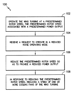
[0035] Referring now to FIG. 8, a flow diagram of one embodiment of a
method 100
that may be implemented by the controller 26 for reducing noise associated
with the
cooling fans 51, 52, 53 as described herein is illustrated. As shown at 102,
the controller
26 is configured to operate the wind turbine 10 in a standard operating mode
at a
predetermined rotor speed. The predetermined rotor speed is associated with a
predetermined power output (e.g. rated power). During normal operation, noise
generated by the cooling fans 51, 52, 53 is generally masked by rotor and/or
wind noise
and is therefore not an issue. Therefore, the fans 51, 52, 53 are typically
operated at full
speed.
[0036] At 104, the method 100 includes receiving a request to operate in a
reduced
noise operating mode. As such, at 106, the method 100 includes reducing the
predetermined rotor speed so as to provide a reduced power output. For
example, many
wind turbines operate in noise reduced operation (NRO) at night so as to be
considerate
of neighboring residents. Still other wind conditions or circumstances may
require NRO.
For example, in certain embodiments, NRO may be activated and deactivated as a
function of wind direction and/or wind speed. In NRO, the wind turbine 10
produces less
power, therefore, there are typically less drivetrain losses and less heat
being generated.
When the rotor speed is reduced, however, the fan noise can become audible and
can
exceed allowable noise limits. As such, at 108, the method 100 includes
reducing the
speed of one or more of the cooling fans 51, 52, 53 of the wind turbine 10 in
response to
reducing the rotor speed. The adjusted fan speed reduces the fan noise such
that when
combined with rotor and/or wind noise, the total noise is less than a noise
threshold.
Since the air temperature is typically lower at night when most NRO occurs,
the reduced
fan speed is still effective at cooling the drivetrain assembly.
[0037] More specifically, in certain embodiments, the controller 26 is
configured to
automatically reduce one or more fan speeds or turn off one or more fans 51,
52, 53 or a
combination thereof in response to reducing the predetermined power set point.
In
further embodiments, the fan speeds may be adjusted manually, for example, by
an
CA 02923292 2016-03-10
279778
operator. Further, depending on the actual fan noise as compared with a noise
threshold,
the controller 26 may turn off one of the fans 51, 52, 53 and/or reduce a
speed of another.
In further embodiments, the controller 26 may turn off all the fans 51, 52, 53
or simply
reduce the speed of all the fans 51, 52, 53. The controller 26 may also be
configured to
correlate the reduction in fan speed with a reduction in rotor speed.
[0038] In additional embodiments, the sensors 59, 60, 61 as described
herein may be
configured to monitor a temperature of the generator 24 and/or gearbox 38
after reducing
the predetermined rotor speed or while operating in NRO. As such, the
controller 26 can
adjust the speed of at least one of the fans 51, 52, 53 based on the
temperature. More
specifically, in a particular embodiment, if the drivetrain temperature
becomes too hot
during NRO and the fan speed is at a maximum for NRO, then the controller 26
can
automatically reduce the rotor speed (rather than increasing fan speed) so as
to maintain
the noise level within allowable limits. In further embodiments, above a
specific wind
speed value (e.g. a measured wind parameter or an estimated wind speed), the
controller
26 may be configured to assume that the wind-induced background noise is able
to mask
the fan noise completely such that the fan speed can be increased so as to
increase the
AEP.
[0039] The controller 26 may also be configured to revert back to normal
operation
after NRO. More specifically, if reduced noise is no longer required, the
controller 26 is
configured to increase the rotor speed back to the predetermined rotor speed
after a
predetermined time period. As such, the controller 26 is configured to
increase the speed
of the fans 51, 52, 53 operating at a reduced speed and/or to turn certain
fans back on
after the predetermined time period. The predetermined time period may
correspond to a
certain number of nighttime hours or may be preconfigured such that the
drivetrain
assembly does not overheat.
[0040] Referring now to FIGS. 6 and 7, multiple graphs are depicted that
illustrate
various advantages of operating the wind turbine 10 according to the present
disclosure.
More specifically, FIG. 6 illustrates a graph 70 of the sound level versus
wind speed for a
11
CA 02923292 2016-03-10
279778
conventional wind turbine, whereas FIG. 7 illustrates a graph 80 of the sound
level versus
wind speed according to the present disclosure. As shown, the total NRO noise
is higher
for the conventional turbine (graph 70) as compared to the present disclosure
(graph 80)
due to the fan noise. As such, in many instances, the total NRO noise of
conventional
turbines exceeds the NRO noise target 72 (e.g. 100dB or any other suitable
threshold). In
contrast, graph 80 illustrates a total NRO noise that is equal to or less than
the target
threshold 82 (with the same blade noise).
[0041] Furthermore, the skilled artisan will recognize the
interchangeability of
various features from different embodiments. Similarly, the various method
steps and
features described, as well as other known equivalents for each such methods
and feature,
can be mixed and matched by one of ordinary skill in this art to construct
additional
systems and techniques in accordance with principles of this disclosure. Of
course, it is
to be understood that not necessarily all such objects or advantages described
above may
be achieved in accordance with any particular embodiment. Thus, for example,
those
skilled in the art will recognize that the systems and techniques described
herein may be
embodied or carried out in a manner that achieves or optimizes one advantage
or group of
advantages as taught herein without necessarily achieving other objects or
advantages as
may be taught or suggested herein.
[0042] While there have been described herein what are considered to be
preferred
and exemplary embodiments of the present invention, other modifications of
these
embodiments falling within the scope of the invention described herein shall
be apparent
to those skilled in the art.
12