Note: Descriptions are shown in the official language in which they were submitted.
CA 02923702 2016-03-15
REVERSIBLE CASE FOR AN ELECTRONIC DEVICE
BACKGROUND OF THE INVENTION
FIELD OF THE INVENTION
The disclosed invention generally relates to a case construction for encasing
an
electronic device such as a laptop type computer, tablet type computer or
mobile
communications device. More particularly, the disclosed invention provides a
reversible
case construction for enabling a user to encase an electronic device and
selectively orient
an outer casing material for visual display.
BRIEF DESCRIPTION OF THE PRIOR ART
Case constructions for use in combination with electronic devices such as
tablet
type computers and the like are well known in this field of art. While the
basic function
of a basic case construction is to protect and/or enclose the device it
encases, the art
continues to develop with an eye toward enhancing functionality of the case
constructions
so as to provide the user with various means of manipulating and/or re-
positioning the
devices.
For example, it may be desirable to provide a case having first and second
decorative case materials which can be selectively chosen to outside
orientation for
providing passersby with visual and/or tactile sensory information from either
of two
decorative case materials while simultaneously protecting the encased device
within or as
1
CA 02923702 2016-03-15
attached to the basal case construction. When the tablet computer or similar
device is
supported in its carrying case during use thereof, the multi-function use of
the case
provides great advantages for utility thereof, while keeping a structure for
the improved
use to a minimum.
It is further noted that tablet type computers and the like are manufactured
in a
variety of sizes and shapes. Accordingly, it is beneficial for a device
mounting
mechanism to adjust to the size and/or contours of the respective device(s),
while still
providing the desired holding and outer cover re-positioning capabilities. A
few of the
more pertinent prior art patent-related disclosures relating to cradle-like
devices for
holding and enabling the re-positioning of the devices they hold are described
hereinafter.
United States Patent Application Publication No. 2006/0187696 ('696
Publication), authored by Lanni, discloses a Cradle for Receiving an Adapter.
The '696
Publication describes a cradle casing having a DC/DC adapter to receive DC
power from
a DC power source and generate a first DC power signal. A sleeve accepts an
AC/DC
adapter, and guides movement of the AC/DC adapter when the AC/DC adapter is
inserted
into the cradle casing. The AC/DC adapter is capable of receiving AC power
from an
AC power source and generating a second DC power signal. A circuit receives at
least
one of the first DC power signal and the second DC power signal and outputs a
third DC
power signal.
United States Patent Application Publication No. 2008/0002369 (`369
Publication), authored by Carnevali, discloses a Portable Device Docking
Station. The
'369 Publication describes an external expanding apparatus or "docking
station' operable
with a portable computer device of a type having a display unit having a
display screen
2
CA 02923702 2016-03-15
on an inner surface thereof and a hard shell backing surface opposite thereof
and
pivotally mounted on a substantially rigid casing having a pair of locating
holes adjacent
to opposite corners of a substantially planar bottom surface thereof, and an
input/output
(I/O) connector positioned on a back plane thereof with a pair of positioning
apertures
provided on opposite sides thereof.
United States Patent Application Publication No. 2011/0261509 ('509
Publication), authored by Xu et al., discloses a Docking Cradle with Floating
Connector
Assembly. The '509 Publication describes a docking cradle for a portable
electronic
device that includes a floating connector assembly. The floating connector
assembly
isolates a portable electronic device connected to the connector assembly from
at least
some of the shock, vibration or other motion imposed on the rest of the
docking cradle.
The connector assembly is positioned above a base frame and comprises a
platform, a device interface on the platform, a device securing mechanism
connected to
the platform and connectable to the portable electronic device to physically
secure the
portable electronic device to the connector assembly; and at least one
connector assembly
spring connecting the connector assembly to the base frame such that the
connector
assembly is movable laterally relative to the base frame.
United States Patent Application Publication No. 2012/0075789 (`789
Publication), authored by DeCamp et al., discloses a Swiveling Base for a
Portable
Computing Device. The '789 Publication describes certain swiveling bases for
portable
computing devices. A swiveling base according to the '789 Publication includes
a base
member and a rotatable member. The base member can be placed on a flat surface
and
rotatably supports the rotatable member. The rotatable member releasably
secures the
3
CA 02923702 2016-03-15
portable computing device and can rotate relative to the base member to
reorient a
display of the portable computing device.
The swiveling bases may further include a control component disposed on the
base member. The control component is disposed on the base member and
facilitates
user interaction with a computing application being executed on the portable
computing
device. The control component may be, for example, a button, a joystick, a D-
pad, a
tactile sensor pad, a touch-sensitive D-pad, a spherical trackball, a slider,
or a sliding
disk.
From a review of the foregoing citations in particular, and from a
consideration of
the prior art in general, it will be seen that the prior art thus perceives a
need for a
reversible case construction for enabling a user to removably receive an
electronic device
as exemplified by a tablet type computer and selectively cover that removably
received
electronic device with an encasing panel assembly with select surfacing of the
case or
cover construction being outwardly presented as summarized in more detail
hereinafter.
SUMMARY OF THE INVENTION
Among the many objectives of this invention is the provision of a reversible
case
construction for encasing and selectively covering and displaying an
electronic device
such as a notebook, laptop, or tablet type computer or similar device. These
and other
readily identifiable objectives of the invention (which other objectives
become clear by
consideration of the specification, claims and drawings as a whole) are met by
providing
4
CA 02923702 2016-03-15
a reversible case construction for an electronic device that cooperates with
an electronic
device for selectively displaying and encasing the same.
To achieve these and other readily identifiable objectives, the present
invention
provides a reversible case construction for encasing an electronic device and
selectively
displaying an outer case material. The reversible case construction according
to the
present invention preferably and summarily comprises a device-holding
mechanism and a
multi-layer, multi-section device-concealing panel assembly.
The device-holding mechanism is preferably sized and shaped to removably
receive an electronic device, and comprises an anterior device-receiving
section and
posterior holder surfacing. The multi-layer, multi-section device-concealing
panel
assembly comprises a first material portion and a second material portion, the
first and
second material portions each comprising inner attachment surfacing, outer
exposable
surfacing, a panel assembly-to-holder interface section, an interface-cover
section, and a
device-encasing section.
The inner attachment surfacing of the interface-cover sections and device-
encasing sections is attached to one another for providing a reversible panel
assembly.
The inner attachment surfacing of the panel assembly-to-holder interface
sections is
attached to structure associated with the device-holding mechanism for
providing a
bifurcated interface panel layer.
The reversible panel assembly is pivotal relative to the bifurcated interface
panel
layer about a first pivot axis located adjacent a line of bifurcation in the
bifurcated
5
CA 02923702 2016-03-15
interface panel layer. The first and second material portions thereby are
selectively
presentable for displaying the outer case material.
The multi-layer, multi-section device-concealing panel assembly may preferably
further comprise an interface structural layer, which interface structural
layer is attached
to the posterior holder surfacing and the inner interface surfacing for
connecting the
multi-layer, multi-section device-concealing panel assembly to the device-
holding
mechanism.
The first and second material portions may preferably comprise differing
physical
properties for enabling the user to select a preferred physical property from
the group
consisting of the differing physical properties for outward presentation of
the preferred
physical property. More particularly, the first and second material portions
comprise
differing visual properties, the differing visual properties for enabling the
user to select a
preferred visual property from the group consisting of the differing visual
properties for
outward presentation of the preferred visual property.
The panel assembly-to-holder interface sections may preferably comprise an
interface magnetic material layer and the device-encasing sections may
preferably
comprise an encasing magnetic material layer. The interface and encasing
magnetic
material layers are positionable so as to become substantially parallel,
opposed and
magnetically attractive to one another when the reversible case construction
is in a closed
configuration for enhancing the closed condition of the reversible case
construction.
6
CA 02923702 2016-03-15
The interface-cover sections may also comprise a cover magnetic material layer
such that the cover and interface magnetic material layers are positionable so
as to
become substantially parallel, opposed, and magnetically attractive to one
another for
enhancing the closed condition.
Select magnetic material layers are preferably embedded within the first and
second material portions, which select magnetic material layers are selected
from the
group consisting of the interface, device-encasing and cover magnetic material
layers.
The select magnetic material layers are so embedded for enhancing the visual
appeal of
the reversible case construction.
The device-encasing sections preferably comprise first and second panel
sections.
The second panel sections are pivotal relative to the first panel sections
about a second
pivot axis extending intermediate the first and second panel sections. The
pivotal first
and second panel sections may thus form basal support for the device-holding
mechanism
and enable the user to support the device-holding mechanism in an oblique
orientation
relative to the first panel sections when the reversible case construction is
in an open
configuration.
In an alternative embodiment, the interface-cover sections are pivotally
attached
to the panel assembly-to-holder interface sections at opposed attachment
points opposite
an interface section aperture. The interface section aperture is designed to
accommodate
a rotation mechanism, which rotation mechanism rotatably connects the device-
holding
mechanism to the panel assembly-to-holder interface sections.
7
CA 02923702 2016-03-15
Other objects of the present invention, as well as particular features,
elements, and
advantages thereof, will be elucidated or become apparent from, the following
description
and the accompanying drawing figures.
8
CA 02923702 2016-03-15
BRIEF DESCRIPTION OF THE DRAWINGS
Other features and objectives of my invention will become more evident from a
consideration of the following brief description of patent drawings:
FIG. 1 is a first frontal perspective view of a preferred reversible case
construction according to the present invention showing a cradle-covering
portion in a
first open configuration to show a first side of the cradle-covering portion.
FIG. 2 is a second frontal perspective view of the preferred reversible case
construction according to the present invention showing the cradle-covering
portion in a
second open configuration to show a second side of the cradle-covering
portion.
FIG. 3 is a first edge view of the preferred reversible case construction
according
to the present invention showing the cradle-covering portion in the second
open
configuration in solid lines and the cradle-covering portion in a series of
intermediary
open configurations between the second open configuration and the first open
configuration in broken lines.
FIG. 4 is a third frontal perspective view of the preferred reversible case
construction according to the present invention showing the cradle-covering
portion in
the second open configuration in solid lines and the cradle-covering portion
in a series of
9
CA 02923702 2016-03-15
intermediary open configurations between the second open configuration and the
first
open configuration in broken lines.
FIG. 5 is a first rear perspective view of a preferred reversible case
construction
according to the present invention showing the cradle-covering portion in the
first open
configuration and showing the second side of the cradle-covering portion.
FIG. 6 is a second rear perspective view of the preferred reversible case
construction according to the present invention showing the cradle-covering
portion in
the second open configuration to show the first side of the cradle-covering
portion.
FIG. 7 is a first frontal plan view of the preferred reversible case
construction
according to the present invention showing the cradle-covering portion in the
first open
configuration to show the first side of the cradle-covering portion with first
coloration
depicted in a small circular section.
FIG. 8 is a second frontal plan view of the preferred reversible case
construction
according to the present invention showing the cradle-covering portion in the
second
open configuration to show the second side of the cradle-covering portion with
second
coloration depicted in a small circular section.
CA 02923702 2016-03-15
FIG. 9 is a rear plan view of a preferred reversible case construction
according to
the present invention showing the cradle-covering portion in the first open
configuration
and showing the second side of the cradle-covering portion.
FIG. 10 is a second edge view of the preferred reversible case construction
according to the present invention showing the cradle-covering portion in a
third open
configuration in solid lines and the cradle-covering portion in a series of
intermediary
open configurations between the third open configuration and a closed
configuration.
FIG. 10A is an enlarged fragmentary sectional view of portions of the
illustrative
matter otherwise depicted in FIG. 10, enlarged for greater clarity of said
portions.
FIG. 11 is a third edge view of the preferred reversible case construction
according to the present invention showing the cradle-covering portion in the
first open
configuration.
FIG. 11A is an enlarged fragmentary sectional view of the lowermost structures
otherwise depicted in FIG. 11, enlarged for greater clarity of said
structures.
FIG. 11B is an enlarged fragmentary sectional depiction of small circular
depiction
of the second coloration otherwise depicted in FIG. 7 and FIG. 11A.
11
CA 02923702 2016-03-15
FIG. 11C is an enlarged fragmentary sectional depiction of small circular
depiction
of the first coloration otherwise depicted in FIG. 8 and FIG. 11A.
FIG. 12 is a posterior plan view of the preferred reversible case construction
according to the present invention showing the posterior surfacing of the
reversible case
construction in a first closed configuration.
FIG. 13 is an anterior plan view of the preferred reversible case construction
according to the present invention showing the anterior surfacing of the
reversible case
construction in the first closed configuration.
FIG. 14 is a first rear perspective view of a first alternative reversible
case
construction according to the present invention showing a first alternative
device-holding
mechanism and showing the cradle-covering portion in the second open
configuration and
showing the second side of the cradle-covering portion with first coloration
depicted in a
small circular section.
FIG. 15 is a second rear perspective view of the first alternative reversible
case
construction according to the present invention showing the first alternative
device-holding
mechanism and showing the cradle-covering portion in the first open
configuration and
showing the first side of the cradle-covering portion with second coloration
depicted in a
small circular section.
12
CA 02923702 2016-03-15
FIG. 16 is a top edge view of the preferred reversible case construction
according
to the present invention in the first closed configuration.
FIG. 16A is an enlarged fragmentary sectional view of the leftmost structures
otherwise depicted in FIG. 16, enlarged for greater clarity of said
structures.
FIG. 16B is an enlarged fragmentary sectional view of the center bottom
structures
otherwise depicted in FIG. 16, enlarged for greater clarity of said
structures.
FIG. 17 is a closed lateral edge view of the preferred reversible case
construction
according to the present invention in the first closed configuration.
FIG. 18 is an open lateral edge view of the preferred reversible case
construction
according to the present invention in the first closed configuration.
FIG. 19 is a lateral edge view of a diagrammatic reversible case construction
according to the present invention shown in a first open condition of use.
FIG. 19A is an enlarged fragmentary sectional view of the center structures
otherwise depicted in FIG. 19, enlarged for greater clarity of said
structures.
FIG. 20 is a first frontal perspective of a second alternative device-holding
mechanism according to the present invention.
13
CA 02923702 2016-03-15
FIG. 20A is a second frontal perspective of the second alternative device-
holding
mechanism according to the present invention shown holding a generic
electronic device.
FIG. 21 is a first frontal perspective of a third alternative device-holding
mechanism
according to the present invention.
FIG. 21A is a second frontal perspective of the third alternative device-
holding
mechanism according to the present invention shown holding a generic
electronic device.
FIG. 22 is a reduced frontal plan view of a second alternative embodiment of
the
reversible case construction according to the present invention in the first
open configuration
and showing a fourth alternative device-holding mechanism.
FIG. 23 is a reduced frontal plan view of a third alternative embodiment of
the
reversible case construction according to the present invention in the second
open
configuration and showing a fifth alternative device-holding mechanism.
FIG. 24 is a reduced frontal plan view of a fourth alternative embodiment of
the
reversible case construction according to the present invention in the first
open configuration
and showing the second alternative device-holding mechanism.
14
CA 02923702 2016-03-15
FIG. 25 is a reduced frontal plan view of the first alternative embodiment of
the
reversible case construction according to the present invention in the second
open
configuration and showing the first alternative device-holding mechanism.
15
CA 02923702 2016-03-15
DETAILED DESCRIPTION OF THE PREFERRED EMBODIMENTS
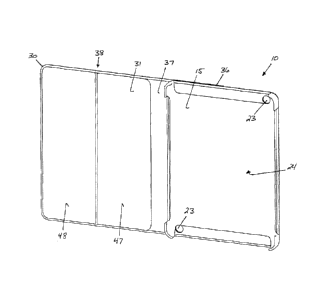
Referring now to the drawings with more specificity, the present invention
preferably provides a reversible case construction as variously exemplified by
four
exemplary embodiments as at primary or preferred embodiment 10, and alterative
exemplary embodiments 11, 12, 13, and 14. The reversible case construction
according
to the present invention basically functions to (a) encase an electronic
device as
generically depicted and referenced at 110, and (b) enable a user to
selectively display an
outer preferred case material in a reversible manner as will be more fully
understood
from a consideration of these detailed descriptions.
To achieve these primary functions, the reversible case construction according
to
the present invention preferably comprises a device-holding mechanism as
variously
exemplified by a first fixed cradle construction as at 15, a second fixed
cradle
construction as at 15', a third fixed cradle construction as at 16, a
rotatable cradle
assembly as at 17, a first universal device-holding board as at 18, and a
second universal
device-holding board as at 19. The first and second universal device-holding
boards 18
and 19 are basically variants of the same type of device-holding mechanism
incorporating
elastomeric material as at 20 having variously shaped apertures 21 formed
therein for
forming straps 55 that resiliently receive and retain corners 22 of an
electronic device 110
for resiliently retaining or holding such a device 110.
Similarly, the first, second, and third fixed cradle constructions 15, 15' and
16 are
basically variants of the same type of device-holding mechanism incorporating
or being
formed from a relatively more rigid material as compared to the elastomeric
material 20
16
CA 02923702 2016-03-15
sized and shaped to receive a specifically sized and shaped electronic device
110. The
cradle constructions 15, 15' and 16 basically only differ structurally in
terms of where
device-accommodating apertures or cut-outs 23 may be preferably formed in the
cradle
construction 15, 15', 16 for cooperating with various functional features of
the electronic
device 10 received thereby.
The device-holding mechanism according to the present invention, as variously
exemplified at 10, 11, 12, 13, and 14, is preferably and essentially sized and
shaped to
removably receive and retain an electronic device 110, and preferably
comprises an
anterior device-receiving section 24, posterior holder surfacing as at 25, a
holder length
as at 26 (extending in a top-to-bottom dimension), a holder width as at 27,
and a holder
thickness as at 28. The device-holding mechanism according to the present
invention
may be of any number of types of constructions and made cooperable with a
multi-layer,
multi-section device-concealing panel assembly as at 30, which multi-layer,
multi-section
device-concealing panel assembly 30 is believed central to the practice of the
present
invention.
The multi-layer, multi-section device-concealing panel assembly 30 according
to
the present invention preferably and essentially comprises a first material
portion or layer
as at 31 and a second material portion or layer as at 32. The first and second
material
portions or layers 31 and 32 each preferably comprise inner attachment
surfacing 33,
outer exposed or selectively exposable surfacing 34, a panel assembly-to-
holder interface
section as at 35, an interface-cover section as at 36, a holder-device edge-
traversing
section 37, and a device-encasing section as at 38.
17
CA 02923702 2016-03-15
The inner attachment surfacing 33 of the interface-cover sections, the holder-
device edge-traversing sections 37 and device-encasing sections 38 are
attached to one
another for providing a reversible case panel assembly. The inner attachment
surfacing
33 of the panel assembly-to-holder interface sections 35 are preferably
attached to
structure associated with the device-holding mechanism for providing a
(single)
bifurcated interface panel layer as at 39.
The preferred structure associated with the device-holding mechanism may be
preferably defined by an interfacing panel assembly-to-holder structural layer
or board as
at 40. Thus, the multi-panel, multi-layer device-concealing panel assembly 30
may be
said to further preferably comprise the interfacing panel assembly-to-holder
structural
layer or board 40. The panel assembly-to-holder structural layer or board 40
is fixedly
attached to the posterior holder surfacing 25 and the inner interface
surfacing 33 for
connecting the multi-panel, multi-layer device-concealing panel assembly 30 to
the select
device-holding mechanism. The interface structural layer or board 40 and panel
assembly-to-holder interface sections 35 may also be outfitted with device-
accommodating apertures or cut-outs 23.
The reversible panel assembly, comprising the noted sections or panel
portions, is
preferably pivotal relative to the bifurcated interface panel layer 39 about a
first or
primary pivot axis 100 basically located at or adjacent the line of
bifurcation 101 in the
bifurcated interface panel layer 39. Figure Nos. 3 and 4 attempt to depict the
reversible
panel assembly being rotated about the pivot axis 100 in various phantom
stages for
reversing the reversible panel assembly relative to the device-holding
mechanism as
exemplified by cradle 15.
18
CA 02923702 2016-03-15
Reversible properties are well known in the arts and typically provide two
finished usable sides or provide some article that is usable with either of
two sides in an
outward manner. Accordingly, the first and second material portions 31 and 32
preferably comprise differing physical properties, including but not limited
to differing
perceptually tactile and visual properties for enabling the user to select a
preferred
physical property from the group consisting of the differing physical
properties for
outward presentation of the preferred physical property at any given time.
In this regard, the first and second material portions 31 and 32 primarily and
preferably comprise differing visual properties for enabling the user to
select a preferred
visual property from the group consisting of the differing visual properties
for outward
appearances. Comparatively referencing Figure Nos. 7, 8, 10A, 11A, 11B, 11C,
14, 15,
16, and 16B the reader will there see depictions of vertical hatch markings as
at 41 and
horizontal hatch markings as at 42. Vertical hatch markings 41 represent a
first group of
physical (e.g. visual) properties and horizontal hatch markings 42 represent a
second
group of physical (e.g. visual) properties.
The vertical hatch markings 41 have been chosen to represent a first type of
physical property only and should not be construed to embrace only a first
type of
coloration characterized by red or pink under the color hatch marking examples
of 37
C.F.R. 1.84(n). Similarly, horizontal hatch markings 42 have been chosen to
represent a
second type of physical property only and should not be construed to embrace
only a
second coloration characterized by blue under the color hatch marking examples
of 37
C.F.R. 1.84(n).
19
CA 02923702 2016-03-15
As indicated, the first and second material portions 31 and 31 each preferably
comprise a holder-device edge-traversing section 37. The holder-device edge-
traversing
section(s) 37 are preferably dimensioned for traversing the holder edge
thickness 28 as
well as the thickness of the panel assembly-to-holder structural layer or
board 40 for
enabling the device-encasing section(s) 38 to more properly cover or encase
the
electronic device 110 as received in the select device-holding mechanism when
the
reversible case construction is in a closed configuration as generally
depicted in phantom
in Figure No. 10, and as generally further depicted in Figure Nos. 12, 13, and
16¨ 18.
The panel assembly-to-holder interface sections 35 may further preferably
comprise an interface magnetic material layer as at 43 and the device-encasing
sections
comprise an encasing magnetic material layer as at 44. The interface and
encasing
magnetic material layers 43 and 44 are substantially parallel and opposed when
the
reversible case construction is in the closed configuration and thus are
magnetically
attractive to one another as at force vectors 102 for enhancing the closed
condition of the
reversible case construction when in the closed configuration.
Similarly, the interface-cover sections 36 may further preferably comprise a
cover
magnetic material layer as at 45. The cover and interface magnetic material
layers 45 and
43 are substantially parallel, opposed, and magnetically attractive to one
another for
enhancing the closed condition of the reversible case construction when in the
closed
configuration. Arrows 103 in Figure Nos. 10 and 10A attempt to depict an
attractive
force between the interface magnetic material layer 43 of the panel assembly-
to-holder
interface section 35 of the first material layer or portion 31 and the cover
magnetic
material layer 45 of the interface-cover section(s) 36.
CA 02923702 2016-03-15
Figure Nos. 10 and 10A depict the reversible case construction in a process of
being reoriented into the closed condition and thus the cover and interface
magnetic
material layers 45 and 43 are not yet substantially parallel but are opposed
and
magnetically attractive to one another as at arrows 103 for enhancing the
closed condition
of the reversible case construction when in the closed configuration. Figure
Nos. 16 and
16B may be thought of as depicting the panel assembly-to-holder interface
section 35 of
the first material layer or portion 31 magnetically attracted to the interface
cover sections
36 via the boundary 46 therebetween.
The various magnetic material layers 43, 44, and 45 are preferably embedded
within the first and second material layers or portions 31 and 32 as variously
depicted,
thereby adding thickness to the first and second material layers or portions
31 and 32 and
forming what appear to be raised panel portions. Thus, the invention may be
said to
preferably comprise select magnetic material layers embedded within the first
and second
material portions 31 and/or 32, which select magnetic material layers are
selected from
the group consisting of the interface, device-encasing and cover magnetic
material layers
43, 44, and 45 for enhancing the visual appeal of the reversible case
construction.
Perhaps most notably in this last regard, the device-encasing sections 38 each
preferably comprise a first or inner panel section as at 47, and a second or
outer panel
section as at 48. The second panel sections 48 are preferably pivotal relative
to the first
panel sections 47 about a second or secondary pivot axis as at 104 extending
intermediate
the first and second panel sections 47 and 48. The reader is directed to
Figure No. 19,
which figure more or less diagrammatically depicts a reversible case
construction in an
21
CA 02923702 2016-03-15
open configuration such that the device-holding mechanism 15 is supported via
the
folded or pivoted reversible panel assembly of the reversible case
construction.
In other words, the first and second panel sections 47 and 48 may thus
function to
form basal support for the device-holding mechanism (as at 15 in Figure No.
19) for
enabling the user to support the device-holding mechanism in an oblique
orientation
relative to the first panel section(s) 47 when in an open case configuration
as generally
depicted in Figure No. 19. Third and fourth or tertiary pivot axes as at 105
are located at
the edges of and thus bound the holder-device edge-traversing section 37 for
enhancing
the basal support functionality as depicted in Figure No. 19, and further for
enabling full
device enclose via the reversible panel assembly as generally depicted in
Figure Nos. 10,
10A, and 16.
With regard to the rotatable cradle embodiment depicted and referenced at 12
in
Figure Nos. 14, 15, and 25, the reader will see that the interface-cover
sections are
slightly modified as compared to interface-cover sections 36 and thus have
been
referenced at 36'. The cover sections 36' are pivotally attached to the panel
assembly-to-
holder interface sections 35' at opposed attachment points 50 opposite
interface section
apertures formed in the cover sections 36'. The interface section apertures
formed in the
cover sections 36' coincide with apertures formed in the panel assembly-to-
holder
interface sections 35', and may be of any number of shaped formations.
A semi-circular formation as at 51 and a rectangular formation as at 52 have
been
illustrated in the cover sections 36' for the purpose of exemplifying this
concept. The
semi-circular formation 51 and the rectangular formation 52 coincide with semi-
circular
formation as at 53 and rectangular formation as at 54 formed in the panel
assembly-to-
22
CA 02923702 2016-03-15
holder interface sections 35'. The formations here exemplified are
contemplated for
structurally accommodating a rotation mechanism as at 49 rotatably attaching
or
connecting the device-holding mechanism to the panel assembly-to-holder
interface
sections 35' (optionally via structural layer 40). Generally speaking the top-
to-bottom
dimensions of the sections 35', 36' and 37' are relatively abbreviated as
compared to
sections 35, 36, and 37.
While the above descriptions contain much specificity, this specificity should
not
be construed as limitations on the scope of the invention, but rather as an
exemplification
of the invention. The basic invention may be said to essentially teach or
disclose a
reversible case construction for encasing an electronic device and selectively
displaying
an outer case material. The reversible case construction essentially comprises
a device-
holding mechanism or device-holding means sized and shaped to removably
receive and
hold an electronic device.
The reversible case construction further essentially comprises a device-
concealing
reversible panel assembly. The device-concealing reversible panel assembly
comprises
first and second material portions, each of which preferably comprise inner
surfacing,
outer surfacing, a panel assembly-to-holder interface section, an interface-
cover section,
and a device-encasing section. The inner surfacing of the interface-cover
sections and
device-encasing sections are attached to one another.
The inner surfacing of the panel assembly-to-holder interface sections are
attached to structure associated with the device-holding mechanism for
providing an
interface panel layer. The reversible panel assembly is pivotal relative to
the interface
panel layer about a first pivot axis located adjacent interface panel layer.
The first and
23
CA 02923702 2016-03-15
second material portions are thereby being selectively presentable for
displaying the outer
case material.
The device-concealing panel assembly of the reversible case construction may
further preferably comprise an interface structural layer. The interface
structural layer is
preferably attached to the device-holding mechanism and the inner surfacing
for
connecting the device-concealing panel assembly to the device-holding
mechanism or
means.
The first and second material portions of the reversible case construction
preferably comprise differing physical properties for enabling the user to
select a
preferred physical property from the group consisting of the differing
physical properties
for outward presentation. More particularly, the first and second material
portions may
preferably comprise differing visual properties for enabling the user to
select a preferred
visual property from the group consisting of the differing visual properties
for outward
presentation of the preferred visual property.
The panel assembly-to-holder interface sections may preferably comprise an
interface magnetic material layer and the device-encasing sections may
preferably
comprise an encasing magnetic material layer. The interface and encasing
magnetic
material layers are substantially parallel and opposed and magnetically
attractive to one
another when the reversible case construction is in a closed configuration for
generally
enhancing the closed condition of the reversible case construction via
magnetically
attractive forces between the magnetic material layers.
The interface-cover sections may also comprise a cover magnetic material layer
such that the cover and interface magnetic material layers are substantially
parallel,
24
CA 02923702 2016-03-15
opposed, and magnetically attractive to one another for further enhancing the
closed
condition. Select magnetic material layers are preferably embedded within the
first and
second material portions for enhancing the overall visual appeal of the
reversible case
construction. The select magnetic material layers are selected from the group
consisting
of the interface, device-encasing and cover magnetic material layers.
The device-encasing sections may preferably first and second panel sections.
The
second panel sections are preferably pivotal relative to the first panel
sections about a
second pivot axis extending intermediate the first and second panel sections.
The pivotal
first and second panel sections may thus form basal support for the device-
holding
mechanism and enable the user to support the device-holding mechanism in an
oblique
orientation relative to the first panel sections when the reversible case
construction is in
an open configuration.
In an alternative embodiment, the interface-cover sections are preferably
pivotally
attached to the panel assembly-to-holder interface sections at opposed
attachment points
opposite an interface section aperture. In this embodiment, the interface
section aperture
basically functions to accommodate a rotation mechanism, which rotation
mechanism
rotatably connects the device-holding mechanism to the panel assembly-to-
holder
interface sections.
25