Note: Descriptions are shown in the official language in which they were submitted.
CA 023798 2016-038
1
DESCRIPTION
Title of Invention
SEAM WELDING METHOD AND SEAM WELDING DEVICE
Technical Field
The present invention relates to a seam welding method
and a seam welding device for performing seam welding with
respect to a stacked assembly, which is formed by stacking
a plurality of workpieces (includes a plurality of
workpieces stacked), wherein among the workpieces, a
thinnest workpiece having a minimum thickness is arranged
on an outermost side of the stacked assembly.
Background Art
Seam welding is widely known as a technique for
joining metal plates together (for example, see Japanese
Laid-Open Patent Publication No. 2007-167896). Using seam
welding, after stacked metal plates (stacked assembly) are
sandwiched between a pair of roller electrodes, a current
is applied between the roller electrodes. More
specifically, within the stacked assembly, a current
pathway is formed along the stacking direction. A current
that flows out from the plus electrode is conducted
successively through the metal plate in contact with the
plus electrode, contact sites between the metal plates, and
the metal plate in contact with the minus electrode,
whereupon the current reaches the minus electrode.
During application of current, resistance heating
(Joule heat) is generated at the contact sites between the
CA 02923798 2016-03-08
2
metal plates. Thus, melting takes place at such sites.
Thereafter, by the stacked assembly being moved
relative to the pair of roller electrodes, the current
pathway also moves, so that ultimately, the sites at which
resistance heating occurs in the stacked assembly move as
well. That is, the current moves away from the sites that
have been melted prior to such movement, and therefore,
resistance heating of the sites is completed. As a result,
the temperature at the sites decreases, whereby the sites
become solidified and acquire a solid phase. Such
solidified sites are referred to primarily as nuggets.
On the other hand, at the sites corresponding to the
newly formed current pathway, in the same manner as
described above, the contact sites between the metal plates
undergo melting. Thereafter, by sequentially repeating the
above-described phenomenon, the metal plates are joined
continuously to each other.
Summary of Invention
Incidentally, as the stacked assembly, a structure
exists in which plural metal plates of different
thicknesses are stacked. In addition, in the case that the
workpiece (thinnest workpiece) with the smallest thickness
is seam welded while being stacked on the outermost side of
the stacked assembly, a situation occurs in which nuggets
do not grow sufficiently between the thinnest workpiece and
the other workpiece adjacent to the thinnest workpiece. The
reason therefor is assumed to be that adequate resistance
heating does not occur, due to the fact that the specific
resistance is minimal as a result of the thickness of the
CA 023798 2016-038
3
thinnest workpiece being smallest. Although it can be
considered to increase the current value so that nuggets
grow sufficiently large in the vicinity of the thinnest
workpiece, in this case, a defect is brought about in that
so-called spatter (welding debris), a phenomenon that the
workpiece is melted and undergoes scattering, is easily
caused.
The present invention has been devised taking into
consideration the aforementioned problems, and has the
object of providing a seam welding method and a seam
welding device, which enable nuggets of sufficient size to
be formed between a thinnest workpiece arranged on an
outermost side of a stacked assembly and a workpiece
adjacent to the thinnest workpiece, while also dispelling
any concerns over generation of welding debris.
[1] A seam welding method according to the present
invention is characterized by performing seam welding by
sandwiching a stacked assembly between a pair of roller
electrodes, the stacked assembly comprising a plurality of
workpieces stacked, together with arranging a thinnest
workpiece having a smallest thickness on an outermost side,
wherein, in a state in which one of the roller electrodes
in contact with the thinnest workpiece is arranged more
forwardly in the welding direction than the other roller
electrode, supply of current is carried out between the
pair of roller electrodes while the pair of roller
electrodes is moved relatively with respect to the stacked
assembly.
In accordance with the seam welding method according
to the present invention, since the one roller electrode in
CA 02923798 2016-03-08
4
contact with the thinnest workpiece is disposed more
forwardly in the welding direction than the other roller
electrode, in the stacked assembly, a current pathway,
which is inclined in a direction opposite to the welding
direction, is formed from the one roller electrode toward
the other roller electrode. When this is done, in the
current pathway, at a certain point in time Ti, resistance
heating occurs at a contact site (first contact site)
between the thinnest workpiece and the workpiece adjacent
to the thinnest workpiece. In addition, at a point in time
T2 at which the pair of roller electrodes is moved
relatively with respect to the stacked assembly, a second
site adjacent to the first site in the welding direction is
heated, together with a third site adjacent to the other
roller electrode side of the first site being heated. At
this time, the first site, which already has been heated,
is increased in heat further by the second site and the
third site, and therefore, a nugget (well-proportioned
nugget) of a sufficient size is formed at the first site.
Consequently, a joint is obtained which is superior in
bonding strength.
Further, in the case that the one roller electrode is
arranged more forwardly in the welding direction than the
other roller electrode, in comparison with a situation in
which the two roller electrodes are aligned at the same
position in the welding direction, the contact area of the
respective roller electrodes with respect to the stacked
assembly becomes larger, together with the contact area
between the workpieces becoming larger. Consequently, since
the current density of the current pathway is comparatively
CA 023798 2016-038
small, even in the case that the current value flowing
between the pair of roller electrodes is increased, the
occurrence of welding debris can suitably be suppressed.
[2] In the aforementioned seam welding method, there
5 may be carried out a calculating step of calculating a
ratio of a thickness of the stacked assembly with respect
to the thickness of the thinnest workpiece, and a setting
step of setting an angle of inclination along the welding
direction of a line segment that passes through axes of
rotation of the respective roller electrodes with respect
to a line segment along a stacking direction of the stacked
assembly, depending on the ratio calculated in the
calculating step.
According to such a method, since the angle of
inclination is set corresponding to the ratio of the
thickness of the stacked assembly with respect to the
thickness of the thinnest workpiece, nuggets that are
sufficiently large in size can efficiently be formed in the
stacked assembly.
[3] In the aforementioned seam welding method, in the
setting step, the angle of inclination may be set to 5 or
less. According to such a method, since the angle of
inclination is set to 5 or less, it is possible to prevent
the pair of roller electrodes from becoming excessively
distanced from one another. Consequently, nuggets of
sufficient size can be formed more effectively in the
stacked assembly.
[4] A seam welding device according to the present
invention is characterized by performing seam welding by
sandwiching a stacked assembly between a pair of roller
CA 023798 2016-038
6
electrodes, the stacked assembly comprising a plurality of
workpieces stacked, together with arranging a thinnest
workpiece having a smallest thickness on an outermost side,
wherein one of the roller electrodes in contact with the
thinnest workpiece is arranged more forwardly in the
welding direction than the other roller electrode.
In accordance with the seam welding device according
to the present invention, since the one roller electrode in
contact with the thinnest workpiece is disposed more
forwardly in the welding direction than the other roller
electrode, the same effects as those of the aforementioned
seam welding method can be offered.
[5] In the aforementioned seam welding device, there
may be provided a ratio calculating unit configured to
calculate a ratio of a thickness of the stacked assembly
with respect to the thickness of the thinnest workpiece,
and an inclination angle setting unit configured to set an
angle of inclination along the welding direction of a line
segment that passes through axes of rotation of the
respective roller electrodes with respect to a line segment
along a stacking direction of the stacked assembly, based
on the ratio calculated by the ratio calculating unit.
According to such a device, since the angle of
inclination is set based on the ratio that is calculated by
the ratio calculating unit, nuggets that are sufficiently
large in size can efficiently be formed in the stacked
assembly.
[6] In the aforementioned seam welding device, the
inclination angle setting unit may set the angle of
inclination to 50 or less. According to such a device,
81795349
7
since the angle of inclination is set to 5 or less, it is
possible to prevent the pair of roller electrodes from becoming
excessively distanced from one another. Consequently, nuggets
of sufficient size can be formed more effectively in the
stacked assembly.
As has been described above, according to the present
invention, since the one roller electrode in contact with the
thinnest workpiece is disposed more forwardly in the welding
direction than the other roller electrode, nuggets of
sufficient size can be formed in the stacked assembly between
the thinnest workplace arranged on the outermost side and a
workpiece that lies adjacent to the thinnest workpiece. In
addition, since the contact area between the workpieces and
the contact area of the respective roller electrodes with
respect to the stacked assembly can be made larger, any
concerns over generation of welding debris can be dispensed
with.
According to an embodiment, there is provided a seam
welding method for performing seam welding by sandwiching a
stacked assembly between a pair of roller electrodes, the
stacked assembly comprising a plurality of workpieces stacked,
together with arranging a thinnest workpiece having a smallest
thickness on an outermost side; wherein the pair of roller
electrodes are connected to a welding power source such that
the pair of roller electrodes have opposite polarity with
respect to each other, and in a state in which one of the
roller electrodes in contact with the thinnest workpiece is
arranged more forwardly in the welding direction than the
other roller electrode, supply of current is carried out
CA 2923798 2018-02-27
81795349
7a
between the pair of roller electrodes while the pair of roller
electrodes is moved relatively with respect to the stacked
assembly, so that a current pathway inclined in a direction
opposite to the welding direction is formed, the current
pathway being inclined more from the one of the roller
electrodes toward the other of the roller electrodes.
According to another embodiment, there is provided a
seam welding device that performs seam welding by sandwiching
a stacked assembly between a pair of roller electrodes, the
stacked assembly comprising a plurality of workpieces stacked,
together with arranging a thinnest workpiece having a smallest
thickness on an outermost side; wherein the pair of roller
electrodes are connected to a welding power source such that
the pair of roller electrodes have opposite polarity with
respect to each other, one of the roller electrodes in contact
with the thinnest workpiece is arranged more forwardly in the
welding direction than the other roller electrode, and a
current pathway inclined in a direction opposite to the
welding direction is formed in seam welding, the current
pathway being inclined more from the one of the roller
electrodes toward the other of the roller electrodes.
Brief Description of Drawings
FIG. 1 is an overall side view in outline form of a
seam welding device according to an embodiment of the
present invention;
FIG. 2 is a perspective view of a seam welding machine
shown in FIG. 1;
CA 2923798 2018-02-27
81795349
7b
FIG. 3 is a schematic partial front view of the seam
welding machine;
FIG. 4 is a flowchart for describing a seam welding
method according to an embodiment of the present invention;
FIG. 5 is an explanatory drawing for describing a
state in which a site within a stacked assembly is
CA 2923798 2018-02-27
CA 023798 2016-038
8
sandwiched by a first roller electrode and a second roller
electrode, and the site is warped;
FIG. 6 is a schematic explanatory drawing for
describing a contact area of the first roller electrode
with respect to a first workpiece, and a contact area of
the second roller electrode with respect to a third
workpiece;
FIG. 7A is an explanatory diagram showing a heated
site of the stacked assembly at a time Ti;
FIG. 7B is an explanatory diagram showing a heated
site at a time T2 that is advanced beyond time Ti;
FIG. 7C is an explanatory diagram showing a heated
site at a time T3 that is advanced beyond time T2;
FIG. 8 is a schematic view of a seam welding device
according to a first exemplary embodiment of the present
invention;
FIG. 9 is a cross-sectional view taken along line IX-
IX of FIG. 8;
FIG. 10 is a graph showing experimental results of the
exemplary embodiment of FIG. 8; and
FIG. 11 is an explanatory drawing for describing a
seam welding method according to a modified example of the
present invention.
Description of Embodiments
In relation to a seam welding method and a seam
welding device that implements such a method according to
the present invention, preferred embodiments of the present
invention will be described in detail below with reference
to the accompanying drawings.
CA 2923798 2017-04-10
81795349
9
As shown in FIGS. 1 and 2, a seam welding device 10
according to an embodiment of the present invention performs
seam welding on a stacked assembly 100 that serves as an object
to be welded, and is equipped with a multi-jointed articulated
robot 12, a seam welding machine 16 supported on a distal end
arm 14 of the articulated robot 12, an input unit 17, and a
control unit 18.
First, a description will be given concerning the stacked
assembly 100. The stacked assembly 100 according to the present
invention is a member that is used as a door opening portion of
an automobile, which is formed by stacking three workpieces
(metal plates) Wl, W2, W3.
The workpiece Wl, for example, is made up from high-
tensile steel such as JAC590, JA0780 or JAC980, which are high-
performance high-tensile steel sheets defined according to the
Japan Iron and Steel Federation Standard (institutor(s) of the
Japan Iron and Steel Federation, "Hot-dip galvannealed steel
sheet and strip for automobile use", the Japan Iron and Steel
Federation, April 1, 2008), and forms one outermost layer
(outermost surface) of the stacked assembly 100. The workpiece
W2 is made up from the same material (high-tensile material) as
the aforementioned workpiece W1, and forms a middle layer of
the stacked assembly 100. The workpiece W3, for example, is
made up from JAC270 (a so-called mild steel, which is a high-
performance steel sheet for press-forming defined according to
the Japan Iron and Steel Federation Standard), and forms the
other outermost layer (outermost surface) of the stacked
assembly 100.
CA 2923798 2017-04-10
81795349
9a
Therefore, in the stacked assembly 100 of the present
embodiment, in comparison with the workpiece W1 and the
workpiece W2, which are high-tensile steel materials, the
workpiece W3, which is a mild steel material, has a
CA 02923798 2016-03-08
characteristic of being relatively difficult to generate
heat therein, due to the fact that the specific resistance
thereof is low and the thermal conductivity thereof is
high.
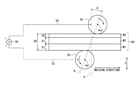
5 As understood from FIG. 3, the thickness of the
workpiece W1 and the thickness of the workpiece W2 are set
to D1 (e.g., roughly 1 mm to roughly 2 mm), whereas the
thickness of the workpiece W3 is set to a smaller dimension
D2 (e.g., roughly 0.5 mm to roughly 0.7 mm) than the
10 thickness Dl. Stated otherwise, the workpiece W3 is the
thinnest workpiece of the stacked assembly 100. The
thickness of the workpiece W1 and the thickness of the
workpiece W2 need not be the same and may differ from each
other.
The articulated robot 12 is configured as a so-called
industrial robot. Under the action of the control unit 18,
the articulated robot 12 can move the seam welding machine
16 in an arbitrary posture and at an arbitrary position
(see FIG. 1).
The seam welding machine 16 includes a guide rail 20,
which is fixed through a mount 19 with respect to the
distal end arm 14 of the articulated robot 12, a first
drive mechanism 22 and a second drive mechanism 24, which
are disposed on the guide rail 20, a first roller electrode
26, which is disposed on the first drive mechanism 22, and
a second roller electrode 28, which is disposed on the
second drive mechanism 24.
The guide rail 20 is configured in a rectangular
parallelepiped shape, and substantially in a central part
in the widthwise direction (the direction of the arrow Z in
CA 023798 2016-038
11
FIG. 2) of a surface on an opposite side from the side on
which the distal end arm 14 is positioned, a protrusion 30
is formed that spans across the entire length thereof.
The first drive mechanism 22 includes a first moving
table 32 disposed movably with respect to the guide rail 20
along the direction of extension (the direction of the
arrow Y) of the guide rail 20, and a first rotary shaft 34
disposed on the first moving table 32 and to which the
first roller electrode 26 is fixed.
A recess 36, which engages slidably with the
protrusion 30 of the guide rail 20, is formed on the first
moving table 32. By a first cylinder and a first rod (not
illustrated), for example, which are provided on the guide
rail 20, the first moving table 32 is capable of moving
with respect to the guide rail 20 along the direction of
extension of the guide rail 20.
The first rotary shaft 34 extends along the thickness
direction (the direction perpendicular to the direction of
the arrow Y and the direction of the arrow Z) of the guide
rail 20, and is capable of being rotated by a non-
illustrated first rotary motor that is disposed on the
first moving table 32.
The second drive mechanism 24 includes a second moving
table 38 disposed movably with respect to the guide rail 20
along the direction of extension (the direction of the
arrow Y) of the guide rail 20, a third moving table 40
disposed movably with respect to the second moving table 38
along the widthwise direction (the direction of the arrow Z
in FIG. 2) of the guide rail 20, and a second rotary shaft
42 disposed on the third moving table 40 and to which the
CA 02923798 2016-03-08
12
second roller electrode 28 is fixed.
A recess 44, which engages slidably with the
protrusion 30 of the guide rail 20, is formed on the second
moving table 38. By a second cylinder and a second rod (not
illustrated), for example, which are provided on the guide
rail 20, the second moving table 38 is capable of moving
with respect to the guide rail 20 along the direction of
extension of the guide rail 20. On a surface on an opposite
side from the surface on which the recess 44 is formed in
the second moving table 38, a protrusion 46 is formed that
spans across the entire length of the guide rail 20.
A recess 48, which engages slidably with the
protrusion 46 of the second moving table 38, is formed on
the third moving table 40. By a third cylinder and a third
rod (not illustrated), for example, which are provided on
the second moving table 38, the third moving table 40 is
capable of moving with respect to the second moving table
38 along the widthwise direction (the direction of the
arrow Z) of the guide rail 20.
The second rotary shaft 42 is capable of being rotated
by a non-illustrated second rotary motor that is disposed
on the third moving table 40 in a state of being arranged
parallel to the first rotary shaft 34.
Each of the first roller electrode 26 and the second
roller electrode 28 is formed in a disc shape. As
understood from FIGS. 2 and 3, an outer circumferential
surface of the first roller electrode 26 contacts one
surface of the stacked assembly 100 (workpiece W1), and an
outer circumferential surface of the second roller
electrode 28 contacts the other surface of the stacked
CA 02923798 2016-03-08
13
assembly 100 (workpiece W3). The first roller electrode 26
and the second roller electrode 28 may be formed with the
same structure, and may be formed such that the two
electrodes differ in a dimension in the diametrical
direction or in the widthwise direction .
The seam welding machine 16 includes a welding power
source unit 50, a first lead wire (power line) 52 that
electrically connects the first roller electrode 26 and a
negative electrode of the welding power source unit 50, and
a second lead wire (power line) 54 that electrically
connects the second roller electrode 28 and a positive
electrode of the welding power source unit 50 (see FIGS. 1
and 3).
The welding power source unit 50 is constituted to
include an AC power source and a welding transformer, etc.,
and performs supply of current between the first roller
electrode 26 and the second roller electrode 28 through the
first lead wire 52 and the second lead wire 54.
The input unit 17 is capable of inputting information
with respect to the control unit 18, such as the plate
thicknesses of the respective workpieces W1 to W3 that make
up the stacked assembly 100.
The control unit 18 includes a robot controller 58, a
plate thickness ratio calculating unit 59, an inclination
angle setting unit 60, and a welding machine controller 62.
The robot controller 58 controls driving of the articulated
robot 12.
The plate thickness ratio calculating unit 59
calculates the ratio (plate thickness ratio R = D2/DO) of
the thickness DO of the stacked assembly 100 with respect
CA 02923798 2016-03-08
14
to the thickness 02 of the workpiece (thinnest workpiece)
W3, based on the thickness information, etc., of the
respective workpieces W1 to W3, which is input from the
input unit 17.
The inclination angle setting unit 60 sets the angle
of inclination 0 of a line segment B along the welding
direction with respect to a line segment A along the
stacking direction (the direction of the arrow Y) of the
stacked assembly 100, based on the plate thickness ratio R
calculated by the plate thickness ratio calculating unit 59
(see FIG. 3). The line segment B passes through the axis of
rotation Axl of the first roller electrode 26 and the axis
of rotation Ax2 of the second roller electrode 28.. More
specifically, the inclination angle setting unit 60 sets
the angle of inclination 0 to become larger as the plate
thickness ratio R becomes larger. By setting the angle of
inclination 0 in this manner, the second roller electrode
28 is arranged more forwardly in the welding direction than
the first roller electrode 26.
According to the present embodiment, the inclination
angle setting unit 60 sets the angle of inclination 0 to
less than or equal to 7 , and more preferably, to less than
or equal to 5 . By setting the angle of inclination in this
manner, excessive separation between the first roller
electrode 26 and the second roller electrode 28 can be
suppressed.
Further, in the case that the plate thickness ratio R
is greater than 5, the inclination angle setting unit 60
preferably sets the angle of inclination 0 within a range
of 3 5 , and in the case that the plate thickness
CA 02923798 2016-03-08
ratio R is less than or equal to 3, the inclination angle
setting unit 60 preferably sets the angle of inclination 0
to be approximately 10.
This is because, if the angle of inclination 0 is too
5 small, it becomes difficult for the contact site between
the workpiece W2 and the workpiece W3 to be sufficiently
heated, whereas if the angle of inclination e is too large,
the current pathway formed in the stacked assembly 100
becomes excessively long (the interval between the first
10 roller electrode 26 and the second roller electrode 28 is
too wide), and the welding current value needed to perform
seam welding becomes excessively large.
The welding machine controller 62 controls the first
through third cylinders, the first and second rotary
15 motors, and the welding power source unit 50.
The seam welding device 10 according to the present
embodiment is constructed basically as has been described
above. Next, effects and advantages of the seam welding
device 10 will be described in relation to a seam welding
method according to the embodiment.
First, the plate thickness ratio calculating unit 59
calculates the plate thickness ratio R by obtaining
information of the thickness dimensions of the respective
workpieces W1 to W3 (step Si of FIG. 4). The thickness
dimensions of the respective workpieces W1 to W3 may be
obtained by the operator making an input to the input unit
17, or may be obtained from workpiece information
(information of the thickness dimensions of each of the
workpieces) stored in advance in a storage unit or the like
of the control unit 18.
CA 02923798 2016-03-08
16
Next, the inclination angle setting unit 60 sets the
angle of inclination 0 based on the calculated thickness
ratio R (step S2). More specifically, the inclination angle
setting unit 60 sets the angle of inclination 0 to become
larger as the plate thickness ratio R becomes larger. At
this time, the inclination angle setting unit 60 sets the
angle of inclination 0 within a range of 30 0 - 50, for
example.
Next, the relative positions of the first roller
electrode 26 and the second roller electrode 28 are
adjusted so as to bring about the set angle of inclination
0 (step S3). More specifically, by controlling the pressure
in the third cylinder, the welding machine controller 62
moves the third moving table 40 in the direction of the
arrow Z, whereby the second roller electrode 28 is moved
more forwardly in the welding direction than the first
roller electrode 26, and the angle of inclination 9 is
placed at the set value.
Thereafter, the stacked assembly 100 is sandwiched and
gripped between the first roller electrode 26 and the
second roller electrode 28 (step S4). More specifically, at
first, the robot controller 58 controls the articulated
robot 12, moves the seam welding machine 16 to the vicinity
of a welding starting point of the stacked assembly 100,
and adjusts the posture of the seam welding machine 16 to
position the first roller electrode 26 on the side of the
workpiece W1 and to position the second roller electrode 28
on the side of the workpiece W3. In addition, by
controlling the pressures in the first and second
cylinders, the welding machine controller 62 causes the
CA 02923798 2016-03-08
17
first roller electrode 26 and the second roller electrode
28 to approach one another mutually. Consequently, the
outer circumferential surface of the first roller electrode
26 contacts one surface of the workpiece Wl, together with
the outer circumferential surface of the second roller
electrode 28 contacting the other surface of the workpiece
W3.
As a result, the stacked assembly 100 is pressed and
sandwiched by the first roller electrode 26 and the second
roller electrode 28. Part of the stacked assembly 100 which
has been sandwiched is warped corresponding to the shapes
of the roller electrodes 26, 28 (see FIG. 5). Therefore,
compared to the case where the roller electrodes 26, 28 are
aligned in the welding direction, a contact area Si of the
first electrode 26 on the workpiece W1 increases along the
welding direction and the widthwise direction of the first
roller electrode 26, and a contact area S2 of the second
roller electrode 26 on the workpiece W3 also increases
along the opposite direction of the welding direction and
the widthwise direction of the second roller electrode 28
(see FIG. 6).
Subsequently, seam welding is carried out by supplying
current while the first roller electrode 26 and the second
roller electrode 28 undergo rotation (rolling) (step S5).
More specifically, the robot controller 58 controls the
articulated robot 12, and while the seam welding machine 16
is moved, the welding machine controller 62 rotates the
first roller electrode 26 by driving the first rotary
motor, and rotates the second roller electrode 28 by
driving the second rotary motor. At roughly the same time,
CA 02923798 2016-03-08
18
the welding machine controller 62 carries out supply of
current between the first roller electrode 26 and the
second roller electrode 28 by driving the welding power
source unit 50.
Upon doing so, in the stacked assembly 100, an
inclined current pathway, which is inclined in a direction
opposite to the welding direction, is formed from the
second roller electrode 28 toward the first roller
electrode 26. Therefore, as shown in FIG. 7A, at a certain
point in time Ti, in the current pathway, resistance
heating takes place at a contact site (first site) Hla
between the workpiece W2 and the workpiece W3, at a site
Hlb in the workpiece W2 slightly more rearwardly than the
contact site Hla, and at a contact site H1c between the
workpiece W1 and the workpiece W2 slightly more rearwardly
than the site Hlb.
In addition, as shown in FIG. 7B, at a point in time
T2 after time Ti, since the first roller electrode 26 and
the second roller electrode 28 are moved slightly in the
welding direction with respect to the stacked assembly 100,
resistance heating then takes place at a contact site
(second site) H2a, which is shifted slightly in the welding
direction from the contact site Hla, at a site 112b (third
site), which is shifted slightly in the welding direction
from the site Hlb, and at a contact site H2c, which is
shifted slightly in the welding direction from the contact
site H1c. At this time, the contact site Hla, which has
already been heated, is subjected to further heating by the
contact site H2a and the contact site H2b.
In addition, as shown in FIG. 7C, at a point in time
CA 02923798 2016-03-08
19
T3 after time T2, similar to the case of time T2,
resistance heating then takes place at a contact site H3a,
which is shifted slightly in the welding direction from the
contact site H2a, at a contact site H3b, which is shifted
slightly in the welding direction from the site H2b, and at
a contact site H3c, which is shifted slightly in the
welding direction from the contact site H2c.
At this time, since the contact site H3c is a contact
site between the workpiece W1 and the workpiece W2, which
are greater in thickness and greater in specific resistance
than the workpiece W3, sufficient resistance heating takes
place.
In the foregoing manner, by performing seam welding in
a state in which the second roller electrode 28 is arranged
more forwardly than the first roller electrode 26, since
the contact site Hla between the workpiece (thinnest
workpiece) W3 and the workpiece W2 for which inadequate
heating is easy to occur are sufficiently heated and
melted, nuggets that are sufficiently large in size can be
formed at the contact site between the workpiece W2 and the
workpiece W3.
Further, according to the present embodiment, because
the nuggets that are formed at the contact site H3c grow up
to the contact site between the workpiece W2 and the
workpiece W3, nuggets which are well-proportioned as a
whole can be obtained. Consequently, this leads to the
workpiece W1 and the workpiece W2 being bonded together
firmly, as well as the workpiece W2 and the workpiece W3
being bonded together firmly.
Thereafter, at a point in time that completion of
CA 023798 2016-038
welding by the first roller electrode 26 and the second
roller electrode 28 is reached, seam welding is brought to
an end (step S6). More specifically, the welding machine
controller 62 controls the welding power source unit 50 and
5 stops current between the first roller electrode 26 and the
second roller electrode 28. Further, by adjusting the
pressures inside the first and second cylinders, the first
roller electrode 26 and the second roller electrode 28 are
separated away from the stacked assembly 100. At this time,
10 the current cycle of seam welding is brought to an end.
According to the present embodiment, since the second
roller electrode 28 in contact with the workpiece (thinnest
workpiece) W3 is disposed more forwardly in the welding
direction than the first roller electrode 26, in the
15 stacked assembly 100, a current pathway, which is inclined
in a direction opposite to the welding direction, is formed
from the second roller electrode 28 toward the first roller
electrode 26. When this is done, in the current pathway, at
a certain point in time Ti, resistance heating occurs at
20 the contact site (first contact site) Hla between the
workpiece W3 and the workpiece W2 adjacent to the workpiece
W3. In addition, at the point in time T2 that the first
roller electrode 26 and the second roller electrode 28 are
moved relatively with respect to the stacked assembly 100,
the second site H2a adjacent to the first site Hla in the
welding direction is heated, together with the third site
H2b adjacent to the first roller electrode 26 side of the
first site Hla being heated. At this time, the first site
Hla, which already has been heated, is increased in heat
further by the second site H2a and the third site H2b, and
CA 02923798 2016-03-08
21
therefore, a nugget (well-proportioned nugget) of a
sufficient size is formed at the first site Hla.
Consequently, a joint is obtained which is superior in
bonding strength.
Further, according to the present embodiment, compared
to a situation in which the positions of the first roller
electrode 26 and the second roller electrode 28 in the
welding direction are aligned, the contact area Si of the
first roller electrode 26 with respect to the workpiece Wl,
and the contact area 52 of the second roller electrode 28
with respect to the workpiece W3 can be increased.
Consequently, since the current density of the current
pathway is comparatively small, even in the case that the
current value flowing between the first roller electrode 26
and the second roller electrode 28 is increased, the
occurrence of welding debris can suitably be suppressed.
Furthermore, according to the present embodiment,
since the angle of inclination 0 is set corresponding to
the ratio R of the thickness DO of the stacked assembly 100
with respect to the thickness D2 of the workpiece W3,
nuggets that are sufficiently large in size can efficiently
be formed in the stacked assembly 100. In addition, since
the angle of inclination 0 is set to 50 or less, excessive
separation between the first roller electrode 26 and the
second roller electrode 28 can be suppressed. Consequently,
nuggets of sufficient size can be formed more effectively
in the stacked assembly 100.
The present invention will be described in greater
detail by presenting the following exemplary embodiment
according to the present invention.
CA 023798 2016-038
22
[First Example]
With the present exemplary embodiment, as shown in
FIGS. 8 and 9, using a seam welding device 200 having the
same structure as the above-described seam welding device
10, after seam welding was performed on a stacked assembly
202 as an object to be welded, a shear strength test was
performed.
As the stacked assembly 202, there were stacked in
this order a workpiece W10 (JAC270F) with a plate thickness
of 0.65 mm, a workpiece W20 (JSC590R) with a plate
thickness of 1.80 mm, and a workpiece W30 (JSC590R) with a
plate thickness of 1.40 mm. More specifically, the plate
thickness R of the stacked assembly 202 was greater than 5
at roughly 5.9, as determined from the equation R = (1.40 +
1.80 + 0.65)/0.65.
With the seam welding device 200 according to the
present exemplary embodiment, a first roller electrode 204
was arranged on the side of the workpiece (thinnest
workpiece) W10, and a second roller electrode 206 was
arranged on the side of the workpiece W30.
For each of the first roller electrode 204 and the
second roller electrode 206, water-cooled roller electrodes
constituted from a copper chromium alloy (CrCu) were used.
Further, a thickness ti of the first roller electrode 204
was set to 10 mm, and the radius of curvature rl of the
outer circumferential surface thereof was set to 15 mm. A
thickness t2 of the second roller electrode 206 was set to
10 mm, and the radius of curvature r2 of the outer
circumferential surface thereof was set to 100 mm.
As welding conditions for the present exemplary
CA 02923798 2016-03-08
23
,
embodiment, the welding speed was set to 4 m/min, the
applied pressure was 450 kgf, a current-supplying cycle
with an energization time of 6 msec and a rest time 6 msec
was used, and the up-slope time was set to 150 msec.
Test results according to the present exemplary
embodiment are shown in FIG. 10. In FIG. 10, the welding
current is shown on the horizontal axis, and the angle of
inclination is shown on the vertical axis. In FIG. 10, 0
indicates a base material fractured sample in which debris
was not generated, C) indicates an interfacial fractured
sample in which debris was not generated, A indicates a
base material fractured sample in which debris was
generated, and X indicates a sample in which peeling
occurred without generation of debris. More specifically,
the portions indicated by 0 and C) imply that the heat input
balance of the respective workpieces W10, W20, W30 was
favorable.
According to the test results, in the case that the
second roller electrode 206 was disposed more forwardly
than the first roller electrode 204 (i.e., in the case that
the angle of inclination was -1 degrees and -3 degrees),
compared to a case in which the angle of inclination is
zero degrees, the welding current width became narrow with
the sample C).
In the case that the angle of inclination was +1
degrees, compared to the angle of inclination being zero
degrees, although the welding current width for the sample
()was the same, the region for the sample C) was shifted
toward the high current side. In the case that the angle of
inclination was +3 degrees, compared to the angle of
CA 02923798 2016-03-08
24
inclination being +1 degrees, the region for the sample C)
was shifted further toward the high current side, while in
part, the results of the sample CD could be obtained. In
the case that the angle of inclination was +5 degrees,
compared to the angle of inclination being +3 degrees, the
welding current width for the sample 0 was widened. In the
case that the angle of inclination was +7 degrees, the
results for samples C) and 0 could not be obtained.
In the foregoing manner, in the case that the plate
thickness ratio R is greater than 5, rather than with the
angle of inclination being zero degrees, it was proven that
weldability was improved when the angle of inclination
resided within a range of 00 < 9 5 .
Further, it was
proven that weldability was further improved when the angle
of inclination resided within the range of 30 0 5 .
The present invention is not limited to the
embodiments described above, and it is a matter of course
that various additional or modified structures could be
adopted therein without deviating from the essential gist
of the present invention.
For example, the seam welding method according to the
present invention is not limited to the example of
performing seam welding with respect to a stacked assembly
100 that is made up by stacking three workpieces Wl, W2,
W3. For example, as shown in FIG. 11, the same effects and
advantages of the aforementioned embodiment can be offered,
even in the case that seam welding is carried out with
respect to a stacked assembly 102 that is constituted by
stacking two workpieces W1 and W3. The same holds true for
a case in which seam welding is carried out with respect to
CA 02923798 2016-03-08
a stacked assembly that is constituted by stacking four or
more workpieces.