Note: Descriptions are shown in the official language in which they were submitted.
CA 02923821 2016.-03-14
HAND TOOL FRAME
BACKGROUND OF THE INVENTION
1. Field of the Invention
The present invention relates to a hand tool frame, and more particularly
to a hand tool frame that may provide a positioning effect to hand tools that
are
mounted on the hand tool frame and may improve the practicality of the hand
tool frame.
2. Description of Related Art
With reference to Fig. 17, a conventional hand tool frame 80 has a track
base 81 and multiple positioning mounts 82. The track base 81 is an elongated
seat and has a front side and a slide rail 811. The slide rail 811 is formed
in the
front side of the track base 81. The positioning mounts 82 are slidably
mounted
in the slide rail 811 of the track base 81. Then, hand tools such as sleeves,
wrenches or screwdrivers may be securely mounted on the positioning mounts
82 to store the hand tools on the track base 81 of the conventional hand tool
frame 80.
Furthermore, when the conventional hand tool frame 80 is used to store
sleeves, each one of the positioning mounts 82 has a sliding seat 821 and an
inserting button 822. The sliding seat 821 is round and is slidably mounted in
the
slide rail 811 of the track base 81 and has a front surface. The inserting
button
822 is rectangular, is formed on and protrudes from the front surface of the
sliding seat 821 and extends out of the slide rail 811. In use, a sleeve 90 is
mounted around the inserting button 822 of one of the positioning mounts 82
without rotating relative to inserting button 822 of the positioning mount 82
CA 02923821 2016-03-14
2
since the inserting button 822 is rectangular. The user needs to rotate the
round
sliding seat 821 of the positioning mount 82 relative to the slide rail 811 to
allow
the sleeve 90 to rotate to enable a number or sign on the sleeve 90 to face
the user.
After rotating the sliding seats 821 of the positioning mounts 82 relative to
the
track base 81, the sleeves 90 that are mounted around the inserting buttons
822 of
the positioning mounts 82 may be adjusted to enable numbers or signs on the
sleeves 90 to face a same direction for the user.
Though the conventional hand tool frame 80 may provide a rotation
adjustment effect to the sleeves, the sliding seats 821 of the positioning
mounts
82 lack engaging structures relative to the slide rail 811 of the track base
81 to
hold the sleeves 90 securely on the track base 81 at specific positions. When
a
sleeve 90 of a large size is mounted around an upper positioning mount 82, the
upper positioning mount 82 may slide downwardly along the slide rail 811 due
to
the weight of the sleeve 90 of a large size and also because the track base 81
is
disposed longitudinally. Then, the sleeve 90 of a large size and the upper
positioning mount 82 may knock against a lower positioning mount 82, and the
positioning mounts 82 may gather at a bottom of the track base 81, and this
may.
hinder the user from clearly observing and distinguishing the sizes of the
sleeves
by the numbers or signs.
Furthermore, when the user wants to take a sleeve 90 of a small size that
is mounted on a lower positioning mount 82, the upper positioning mount 82
may slide downwardly with the large size sleeve 90 to shorten a distance
between the two adjacent positioning mounts 82 and knock against the lower
positioning mount 82. After using the small size sleeve 90, the user needs to
CA 02923821 2016-03-14
3
move the upper positioning mount 82 and the large size sleeve 90 upwardly to
recover the distance between the two adjacent positioning mounts 82 to
re-mount the small size sleeve 90 on the lower positioning mount 82, and this
is
inconvenient in use and storage.
In addition, when the conventional hand tool frame is used to store
wrenches or screwdrivers, since the round sliding seats 821 of the positioning
mounts 82 may rotate and slide relative to the slide rail 811 of the track
base 81,
and the two adjacent positioning mounts cannot hold one of the wrenches or
screwdrivers securely on the track base 81, and this may limit the
practicality of
the conventional hand tool frame.
To overcome the shortcomings, the present invention tends to provide a
hand tool frame to mitigate the aforementioned problems.
SUMMARY OF THE INVENTION
One aspect of the invention is to provide a hand tool frame that may
provide a positioning effect to hand tools that are mounted on the hand tool
frame and may improve the practicality of the hand tool frame.
A hand tool frame in accordance with the present invention has a track
base, a positioning board, at least one positioning mount, and an engaging
structure. The track base has a bottom panel, a slide rail, and a connecting
track.
The positioning board is mounted in the connecting track. The at least one
positioning mount is slidably mounted on the track base, and each has a
sliding
seat and an extending element. The sliding seat is slidably mounted in the
slide
rail and abuts the positioning board. The extending element is formed on the
sliding seat and extends out of the slide rail. The engaging structure is
formed
4
between the positioning board and the at least one positioning mount to enable
the at least one positioning mount to position securely on the positioning
board
without sliding relative to the track base, and has at least one first
engaging
segment and a second engaging segment.
It is another aspect of the invention to provide a hand tool frame
comprising:
a track base being an elongated and longitudinal seat and having
a bottom panel being elongated and having
a front surface;
a rear surface;
a top end; and
a bottom end; and
a slide rail formed on and protruding from the front surface of the
bottom panel between the top end and the bottom end of the bottom panel and
having
a front side;
a front opening formed through the front side of the
slide rail; and
a sliding recess formed in the slide rail between the
front side of the slide rail and the front surface of the bottom panel and
communicating with the front opening;
a positioning board mounted in the track base and having
two long opposite sides;
two free ends;
CA 2923821 2018-09-10
4a
a middle, and the positioning board bent forwardly from the long
opposite sides of the positioning board to the middle of the positioning
board;
a front surface, and the front surface of the positioning board
extending toward the slide rail at the middle of the positioning board; and
a rear surface;
at least one positioning mount slidably mounted on the track base, and
each one of the at least one positioning mount having
a sliding seat slidably mounted in the sliding recess of the slide
rail and abutting the front surface of the positioning board; and
an extending element formed on and protruding forwardly from
the sliding seat and extending out of the slide rail via the front opening to
provide
a tool-holding effect; and
an engaging structure formed between the positioning board and the at
least one positioning mount to enable the at least one positioning mount to
position securely on the positioning board without sliding relative to the
track
base, and having
multiple first engaging segments deposited on the front surface of
the positioning board at the middle of the positioning board at spaced
intervals;
and
a second engaging segment deposited on the sliding seat of the at
least one positioning mount, and selectively engaging one of the first
engaging
segments to hold the at least one positioning mount securely on the
positioning
board without sliding relative to the track base;
wherein when the at least one positioning mount is pushed to move
CA 2923821 2018-09-10
4b
relative to the track base, this enables the second engaging segment of the at
least
one positioning mount to disengage from said one of the first engaging
segments
of the positioning board and to engage with an adjacent one of the first
engaging
segments of the positioning board to provide a sliding-engaging effect.
Other advantages and novel features of the invention will become more
apparent from the following detailed description when taken in conjunction
with
the accompanying drawings.
BRIEF DESCRIPTION OF THE DRAWINGS
Fig. 1 is an enlarged perspective view of a first embodiment of a hand
tool frame in accordance with the present invention;
Fig. 2 is an enlarged and exploded perspective view of the hand tool
frame in Fig. 1;
Fig. 3 is an enlarged cross sectional front side view of the hand tool
frame in Fig. 1;
Fig. 4 is an enlarged side view in partial section of the hand tool frame in
Fig. 1;
Figs. 4A and 4B are enlarged side views of the hand tool frame in Fig. 4;
Fig. 5 is an enlarged operational front side view of the hand tool frame in
Fig. 1, shown with two sleeves of different sizes mounted on the hand tool
frame;
Fig. 6 is a perspective view of a second embodiment of a hand tool frame
in accordance with the present invention;
Fig. 7 is an enlarged and exploded perspective view of the hand tool
frame in Fig. 6;
CA 2923821 2018-09-10
CA 02923821 2016-03-14
Fig. 8 is an enlarged and cross sectional side view of the hand tool frame
in Fig. 6;
Figs. 8A and 8B are enlarged side views of the hand tool frame in Fig. 8;
Fig. 9 is an operational perspective view of the hand tool frame in Fig. 6,
shown with forceps, wrenches and screwdrivers mounted on the hand tool
frame;
Fig. 10 is an enlarged and exploded perspective view of a third
embodiment of a hand tool frame in accordance with the present invention;
Fig. 11 is a perspective view of a fourth embodiment of a hand tool
frame in accordance with the present invention;
Fig. 12 is an enlarged and exploded perspective view of the hand tool
frame in Fig. 11;
Fig. 13 is an operational perspective view of the hand tool frame in Fig.
11, shown with screwdrivers mounted on the hand tool frame;
Fig. 14 is a perspective view of a fifth embodiment of a hand tool frame
in accordance with the present invention;
Fig. 15 is an enlarged and exploded perspective view of the hand tool
frame in Fig. 14;
Fig. 16 is an operational perspective view of the hand tool frame in Fig.
14, shown with wrenches of different sizes mounted on the hand tool frame; and
Fig. 17 is an enlarged and operational front side view of a hand tool
frame in accordance with the prior art, shown with two sleeves mounted on the
hand tool frame.
DETAILED DESCRIPTION OF PREFERRED EMBODIMENT
CA 02923821 2016-03-14
6
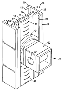
With reference to Figs. 1 to 4, a first embodiment of a hand tool frame in
accordance with the present invention comprises a track base 10, a positioning
board 20, at least one positioning mount 30, and an engaging structure 40.
The track base 10 is made of aluminum, is an elongated seat and has a
bottom panel 11, a slide rail 12, a connecting track 13, and a closed track
14. The
bottom panel 11 is elongated and has a front surface, a rear surface, a top
end,
and a bottom end. The slide rail 12 is formed on and protrudes from the front
surface of the bottom panel 11 between the top end and the bottom end of the
bottom panel 11 and has a front side, a front opening 121, and a sliding
recess
122. The front opening 121 is formed through the front side of the slide rail
12.
The sliding recess 122 is formed in the slide rail 12 between the front side
of the
slide rail 12 and the front surface of the bottom panel 11 and communicates
with
the front opening 121.
The connecting track 13 is formed on and protrudes from the rear
surface of the bottom panel 11, and has a front side, a communicating opening
131, and a connecting recess 132. The front side of the connecting track 13 is
formed on and protrudes from the rear surface of the bottom panel 11. The
communicating opening 131 is formed through the front side of the connecting
track 13 and the rear surface of the bottom panel 11, and communicates with
the
sliding recess 122 of the slide rail 12. The connecting recess 132 is formed
between the bottom panel 11 and the connecting track 13 and communicates
with the communicating opening 131. Additionally, a width of the
communicating opening 131 of the connecting track 13 is narrower than a width
of the front opening 121 of the slide rail 12.
CA 02923821 2016-03-14
7
The closed track 14 is formed on and protrudes from the rear surface of
the bottom panel 11 around the connecting track 13 and has a rear side and a
rear
opening 141 formed through the rear side of the closed track 14. In addition,
the
closed track 14 and the slide rail 12 are formed on the bottom panel 11 as a
single
piece.
The positioning board 20 is elastic, is mounted in the connecting track
13 of the track base 10 and has two long opposite sides, two free ends, a
middle,
a front surface, a rear surface, two rail bars 21, and a through recess 22.
The
positioning board 20 is bent forwardly from the long opposite sides of the
positioning board 20 to the middle of the positioning board 20. Then, the
front
surface of the positioning board 20 at the middle of the positioning board 20
extends at the communicating opening 131 of the connecting track 13.
The two rail bars 21 are formed on and protrude outwardly from the rear
surface of the positioning board 20 respectively at the two long opposite
sides of
the positioning board 20 and are mounted in the connecting recess 132 of the
connecting track 13. The through recess 22 is formed in the rear surface of
the
positioning board 20 at the middle of the positioning board 20 between the
free
ends of the positioning board 20, is parallel with the long opposite sides of
the
positioning board 20 and communicates with the connecting recess 132 of the
connecting track 13. Then, a space is formed between the connecting track 13
and the middle of the positioning board 20, and the space may allow the middle
of the positioning board 20 to deform relative to the track base 10.
The at least one positioning mount 30 is slidably and rotatably mounted
on the track base 10, and each one of the at least one positioning mount 30
has a
CA 02923821 2016-03-14
8
sliding seat 31 and an extending element 32. The sliding seat 31 is round, is
slidably mounted in the sliding recess 122 of the slide rail 12 and abuts the
front
surface o f the positioning board 20. The sliding seat 31 has a rear side and
a front
side. The rear side of the sliding seat 31 faces the communicating opening 131
of
the connecting track 13 and abuts the front surface of the positioning board
20.
The front side of the sliding seat 31 faces the front opening 121 of the slide
rail
12.
The extending element 32 is formed on and protrudes forwardly from
the front side of the sliding seat 31 and extends out of the slide rail 12 via
the
front opening 121. The extending element 32 is used to hold a hand tool.
Furthermore, in the first embodiment of the hand tool frame, the extending
element 32 of each one of the at least one positioning mount 30 is an
inserting
button. The inserting button is hollow, is rectangular and has a side surface
and a
protruding ball 321. The protruding ball 321 is mounted in and extends
outwardly from the side surface of the inserting button. Additionally, in the
first
embodiment, the hand tool frame has multiple positioning mounts 30 slidably
and rotatably mounted on the track base 10 and abutting the positioning board
20.
The engaging structure 40 is formed between the positioning board 20
and the at least one positioning mount 30 to enable the at least one
positioning
mount 30 to position securely on the positioning board 20 without sliding
relative to the track base 10. The engaging structure 40 has at least one
first
engaging segment 41 and a second engaging segment 42.
The at least one first engaging segment 41 is deposited on the front
CA 02923821 2016-03-14
9
surface of the positioning board 20 at the middle of the positioning board 20.
Furthermore, each one of the at least one first engaging segment 41 is a
curved
engaging slot and is formed in the front surface of the positioning board 20
at the
middle of the positioning board 20. In addition, the hand tool frame has
multiple
first engaging segments 41 deposited on the front surface of the positioning
board 20 at spaced intervals to form multiple engaging slots on the
positioning
board 20.
The second engaging segment 42 is deposited on the rear side of the
sliding seat 31 of the at least one positioning mount 30, and selectively
engages
with the at least one first engaging segment 41 to hold the at least one
positioning
mount 30 securely on the positioning board 20 without sliding relative to the
track base 10. In addition, the second engaging segment 42 is an engaging
ring,
is formed on and protrudes from the rear side of the sliding seat 31 of the at
least
one positioning mount 30, and selectively engages one of the engaging slots on
the positioning board 20. Then, the at least one positioning mount 30 may be
securely held on the positioning board 20 without sliding relative to the
track
base 10.
With further reference to Figs. 4, 4A, and 4B, an interval d is between
two adjacent engaging slots of the engaging structure 40, and the engaging
ring
has an inner diameter D, and a mathematical relationship between the interval
d
and the inner diameter D is 5d<D<6d, and this enables a part of the engaging
ring
to engage in one of the engaging slots and the remaining part of the engaging
ring presses against the front surface of the positioning board 20 at the
middle of
the positioning board 20. Then, the abutment relationship between the engaging
CA 02923821 2016-03-14
ring and the positioning board 20 may allow the part of the engaging ring to
engage more securely in the corresponding engaging slot, and the at least one
positioning mount 30 may be securely positioned on the positioning board 20.
With reference to Figs. 4 and 5, when the first embodiment of the hand
tool frame in the present invention is in use, multiple sleeves 60 (large
size), 61
(small size) are respectively and detachably mounted around the inserting
buttons of the positioning mounts 30. When each sleeve 60, 61 is mounted
around the inserting button of a corresponding positioning mount 30, the
protruding ball 321 of the inserting button engages a recess in an inner wall
of
the sleeve 60, 61. Consequently, the sleeves 60, 61 are positioned on the
inserting buttons of the positioning mounts 30. When numbers or signs on the
sleeves 60, 61 are not aligned at a same direction to face a user, the user
may
rotate the sleeves 60, 61 in a clockwise or counterclockwise direction
relative to
the track base 10 as shown in Fig. 5 to enable the numbers or signs of the
sleeves
60, 61 to face the user. During the above-mentioned rotating process, the
sliding
seats 31 of the positioning mounts 30 may be rotated with the sleeves 60, 61
relative to the positioning board 20 by the engagement between the inserting
buttons of the positioning mounts 30 and the sleeves 60, 61.
When the sleeves 60, 61 are rotated to enable the number or sign on the
sleeves 60, 61 to face the user, the engaging structure 40 between the
positioning
board 20 and the at least one positioning mount 30 may enable the engaging
ring
formed on the at least one positioning mount 30 to engage in one of the
engaging
slots formed in the positioning board 20. That is, the engaging structure 40
may
provide a positioning effect to the at least one positioning mount 30 relative
to
CA 02923821 2016-03-14
11
the positioning board 20. Then, the at least one positioning mount 30 may be
positioned securely on the positioning board 20 without rotating relative to
the
track base 10, and the weights of the sleeves 60,61 may not force the
positioning
mounts 30 to move downwardly relative to the track base 10, and the user may
see and distinguish the sizes of the sleeves by the numbers or signs easily
and
conveniently.
Furthermore, when the user wants to take the sleeve 61 (small size) that
is mounted on a lower positioning mount 30, the upper positioning mount 30 is
positioned on the positioning board 20 without sliding downwardly to shorten a
distance between the two adjacent positioning mounts 30 and knocking against
the lower positioning mount 30. After using the small size sleeve 61, the user
may re-mount the small size sleeve 61 on the lower positioning mount 30 easily
without moving the upper positioning mount 30 and the large size sleeve 60
upwardly, and this is convenient in use and storage.
With reference to Figs. 6 to 8, a second embodiment of a hand tool frame
in accordance with the present invention is substantially the same as the
first
embodiment except for the following features. The hand tool frame has at least
one pair of positioning mounts 30B. Each one of the at least one pair of
positioning mounts 30B has a sliding seat 31B and an extending element 32B.
The sliding seat 31B is rectangular and is un-rotatably and slidably mounted
in
the sliding recess 122 of the slide rail 12. The extending element 32B is a
clamping arm and is formed on the front side of the sliding seat 31B and has a
free end and a holding hook 322B. The free end of the clamping arm extends out
of the slide rail 12 via the front opening 121, and the holding hook 322B is
CA 02923821 2016-03-14
12
formed on the free end of the clamping arm. The holding hooks 322B of the at
least one pair of positioning mounts 30B face to each other, and a holding
space
is formed between the clamping arms of the at least one pair of positioning
mounts 30B.
The engaging structure 40B is formed between the positioning board 20
and each one of the at least one pair of positioning mounts 30B, and has a
first
engaging segment 41B and a second engaging segment 428. The first engaging
segment 41B is an elongated engaging slot and is formed in the front surface
of
the positioning board 20 at the middle of the positioning board 20. The second
engaging segment 42B is an elongated engaging rib, is formed on and protrudes
from the rear side of the sliding seat 31B, and selectively engages with the
engaging slot to hold a corresponding positioning mount 30B securely on the
positioning board 20.
With reference to Fig. 9, when the hand tool frame of the second
embodiment in the present invention is in use, different kinds of hand tools
such
as pliers 70, combination spanners 71, adjustable wrenches 72, socket wrenches
73, hexagonal wrenches 74 or screwdrivers 75 may be inserted into a holding
space that is formed between the clamping arms of the at least one pair of
positioning mounts 30B, and the holding hooks 322B may prevent the hand tool
separating from the at least one pair of positioning mounts 3013. Furthermore,
the
holding space between the clamping arms of the at least one pair of
positioning
mounts 30B may be adjusted by moving the sliding seats 31B of the at least one
pair of positioning mounts 30B along the positioning board 20 relative to the
track base 10. After adjusting the holding space between the at least one pair
of
CA 02923821 2016-03-14
13
positioning mounts 30B, the at least one pair of positioning mounts 30B may be
positioned on the positioning board 20 by the engaging structure 40B. Then,
the
different kinds of hand tools may be held securely on the track base 10 by the
positioning mounts 30B, and this will improve the practicality of the hand
tool
frame.
With reference to Fig. 10, a third embodiment of a hand tool frame in
accordance with the present invention is substantially the same as the second
embodiment except for the following features. In the third embodiment, the
first
engaging segment 41C of the engaging structure 40C is an elongated engaging
rib, and is formed on and protrudes from the front surface of the positioning
board 20. Additionally, the second engaging segment 42C of the engaging
structure 40C is an elongated engaging slot, and is formed in the rear side of
the
sliding seat 31C, and selectively engages with the engaging rib to hold a
corresponding positioning mount 30C securely on the positioning board 20.
Furthermore, the operation of the third embodiment of the hand tool
frame is substantially the same as the operation of the second embodiment that
is
mentioned above, and is not described in detail.
With reference to Figs. 11 and 12, a fourth embodiment of a hand tool
frame in accordance with the present invention is substantially the same as
the
first embodiment except for the following features. The hand tool frame
further
has an extending track base 1013 and an additional positioning board 20D. The
extending track base 10D is connected to and parallel with the track base 10
by
an extending panel 15D. Furthermore, the structure of the extending track base
10D is substantially the same as the track base 10, and each one of the track
CA 02923821 2016-03-14
14
bases 10, 10D further has a mounting hole 16, 1613 formed through the
connecting track 13, 131) adjacent to one of the free ends of the connecting
track
13, 13D.
Furthermore, the additional positioning board 20D is mounted in the
extending track base 10D, and the structure of the additional positioning
board
201) is substantially the same as the positioning board 20, and one of the
free
ends of each one of the positioning boards 20, 201) is a closed end, and each
one
of the positioning boards 20, 201) has an engaging protrusion 23, 23D formed
on
the rear surface of the positioning board 20, 20D adjacent to the closed end
of the
positioning board 20, 20D. In assembly, the engaging protrusion 23, 23D of
each
one of the positioning boards 20, 20D engages the mounting hole 16, 16D of a
corresponding track base 10, 101) to hold the positioning board 20, 20D
securely
with the corresponding track base 10, 101).
The at least one positioning mount 301) is mounted in the track base 10
or the extending track base 10D, and each one of the positioning mount 3013
has
a sliding seat 31D and an extending element 32D. The sliding seat 31D is
rectangular and is un-rotatably and slidably mounted in the track base 10 or
the
extending track base 10D. The extending element 32D is a hollow block, is
formed on the front side of the sliding seat 31D, and has two sidewalls, a
front
side, at least one tool hole 3231), a tool slot 324D, and a mounting slit
325D. The
at least one tool hole 323D is formed through the sidewalls of the extending
element 321) to hold a shank 751 of a screwdriver 75 as shown in Fig. 13. The
tool slot 324D is formed through the sidewalls of the extending element 32D
and
communicates with the at least one tool hole 323D. The mounting slit 325D is
CA 02923821 2016-03-14
formed through the front side and the sidewalls of the extending element 32D
and communicates with the at least one tool hole 323D opposite to the tool
slot
324D.
With reference to Fig. 13, when the hand tool frame of the fourth
embodiment in the present invention is in use, a shank 751 of a screwdriver 75
is
inserted into two positioning mounts 30D that are respectively mounted in the
track bases 10, 10D and align with each other via the mounting slits 325D of
the
extending elements 32D, and is held between two tool holes 323D of the
extending elements 32D. Since the positioning mounts 30D are securely
mounted on the track bases 10, 10D by the engaging structure 40D between the
positioning mounts 30D and the positioning boards 20, 20D, the screwdrivers 75
may be securely held on the track bases 10, 10D of the hand tool frame, and
this
may also improve the practicality of the hand tool frame.
With reference to Figs. 14 and 15, a fifth embodiment of a hand tool
frame in accordance with the present invention is substantially the same as
the
first embodiment except for the following features. The hand tool frame
further
has an outer frame 50 connected to the track base 10 and having a first
supporting mount 51, two side supporting racks 52, two clamping panels 53, and
a second supporting mount 54.
The first supporting mount 51 is connected to an end of the track base 10
to provide a holding effect to a user and has a length. The side supporting
racks
52 are connected to the first supporting mount 51 beside the track base 10.
The
clamping panels 53 are respectively mounted in the side supporting racks 52,
and
each one of the clamping panels 53 has multiple clamping claws 531
CA 02923821 2016-03-14
16
continuously formed on a top side of the clamping panel 53 and extending out
of
a corresponding side supporting rack 52. The second supporting mount 54 is
connected to the track base 10 opposite to the first supporting mount 51, is
connected to the side supporting racks 52, and has a length longer than the
length
of the first supporting mount 51. Then, the outer frame 50 is formed as a
trapezoid frame by the supporting mounts 51, 54 and the side supporting racks
52.
The at least one positioning mount 30E is un-rotatably mounted in track
base 10, and each one of the at least one positioning mount 30E has a sliding
seat
31E and an extending element 32E. The sliding seat 31E is rectangular and is
un-rotatably and slidably mounted in the slide rail 12 of the track base 10.
The
extending element 32E is an elastic arm, is formed on the front side of the
sliding
seat 31E, and has a curved segment 326E and a limiting segment 327E. The
curved segment 326E is curvedly formed on and protrudes from the sliding seat
31E and has a free end extending out of the slide rail 12. The limiting
segment
327E is formed on and protrudes from the free end of the curved segment 326E
of the elastic arm to abut against a combination spanner 71 as shown in Fig.
16.
The engaging structure 40E is formed between the positioning board 20
and each one of the at least one positioning mount 30E, and has a first
engaging
segment 41E and a second engaging segment 42E. The first engaging segment
41E is an elongated engaging slot and is formed in the front surface of the
positioning board 20 at the middle of the positioning board 20. The second
engaging segment 42E is an elongated engaging rib, is formed on and protrudes
from the rear side of the sliding seat 31E, and selectively engages with the
CA 02923821 2016-03-14
17
engaging slot to hold a corresponding positioning mount 30E securely on the
positioning board 20.
With reference to Fig. 16, when combination spanners 71 of different
sizes are mounted on the fifth embodiment of the hand tool frame, the
combination spanners 71 are held in the clamping claws 531 of the clamping
panels 53, and the position of the extending element 32E of each one of the
positioning elements 30E may be adjusted by separating the engagement that is
formed by the engaging structure 40E between the positioning board 20 and each
one of the positioning mounts 30E, and moving the positioning mounts 30E
relative to the track base 10 to enable the limiting segment 327E of the
elastic
arm to move close to and abut against a corresponding combination spanner 71.
Furthermore, the curved segment 326E of the elastic arm may be elastically
deformed to closely abut against a corresponding combination spanner 71. Then,
the combination spanners 71 of different sizes can be securely held on the
hand
tool frame between the clamping claws 531 of the clamping panels 53 and the
positioning elements 30E, and this also can improve the practicality of the
hand
tool frame.