Note: Descriptions are shown in the official language in which they were submitted.
CA 02923912 2016-03-15
METHOD AND APPARATUS FOR GENERATING AND FOR FUSING ULTRA-
DENSE HYDROGEN
DESCRIPTION
The invention relates to a method for generating and for
fusing ultra-dense hydrogen according to patent claim 1 as
well as to an apparatus for carrying out the method
according to the preamble of patent claim 6.
In many areas alternative energy sources are being sought
which should in particular obviate the problems of energy
sources based on nuclear reactions or fossil fuels. Here
mention is usually made of fusion processes which should
have the potential to be durable, environmentally friendly
and reliable.
In addition to hot fusion, various fusion processes in the
field of cold fusion have already been described. In this
case these frequently lack demonstrable functionality and
efficiency. A development in the field of cold fusion
towards the use of condensed matter is increasingly
indicated.
For example, EP2680271A1 thus discloses a method and an
apparatus for generating energy by nuclear fusion. In this
case, gaseous hydrogen is catalytically condensed to ultra-
dense hydrogen and collected on a carrier. The carrier is
then brought into a radiation chamber in which the ultra-
dense hydrogen can undergo fusion. Difficulties arise here
in particular from the fact that the carrier must be
transported under constant boundary conditions such as, for
example, vacuum so that the hydrogen cannot volatilize from
its condensed state. The technical implementation of the
method on an industrially usable apparatus can thus be very
cumbersome.
CA 02923912 2016-03-15
- 2 -
In addition to EP2680271A1, mention can also be made of
EP1551032A1. This describes a method for generating heat
based on hydrogen condensates. In particular, hydrogen gas
can be condensed on nanoparticles. For this purpose the
hydrogen gas must be exposed to high pressure. Due to
ultrasound waves the condensed hydrogen atoms can fuse with
one another and thus generate heat. Problematical here is
the use of nanoparticles since as a result of their
reactivity the effects on the environment have hitherto only
been little clarified.
Further known from W02009/125444A1 is a method and an
apparatus for carrying out exothermic reactions between
nickel and hydrogen. Hydrogen gas is brought under pressure
into a tube filled with nickel powder. Under the action of
heat the system can be brought to fusion. In particular the
re-use or removal of nickel as a poisonous heavy metal
appears problematical in this patent specification.
For technical applications under mechanically and thermally
loaded environmental conditions, it has been found that
metallic or ceramic foams specifically for the material of a
fusion reactor are subjected to appreciable requirements
with regard to the temperature resistance. If a stability
above a temperature of 2000 C is to be achieved, only
materials such as, for example, zirconium oxide, silicon
carbide, nitride ceramic, carbon structures or the like
remain. These are either not sufficiently temperature-
resistant under an oxygen atmosphere or are very brittle and
therefore mechanically unstable. Zirconium oxide ceramic,
for example, is also not very stable in its pure form and is
particularly affected by decomposition during use.
Furthermore it is also not suitable to "survive" for long in
a mechanically severely loaded environment with many
vibrations. Even transport has considerable risks with
regard to the mechanical stability of the material.
CA 02923912 2016-03-15
- 3 -
Furthermore, a controlled state must be present. No melting
of the carrier material must occur. The catalyst must not
experience any change in structure and undergo effects of
heat from the fusion or it must revert to its old structure
after the melting process. Thus, a temperature range for a
practicable fusion process can be limited.
Furthermore, the process control of a fusion process
constitutes a problem of reaction delays. If the process
takes place too slowly or too weakly, this is unfavourable
for the efficiency. A certain reactivity is therefore
required so that the process starts sufficiently rapidly
when energy is required.
In addition, radioactive reaction channels can occur or
neutrons can appear. These should be minimized in order to
implement a practical application of the system. Finally the
generated energy should end as heat and less as radiation. A
model of the reaction channels is therefore essential.
It is the object of the invention to provide a method which
eliminates the said disadvantages and enables an
environmentally friendly and efficient generation and fusing
of ultra-dense hydrogen. Environmentally friendly means in
particular avoiding the formation of radioactive isotopes
and using toxic chemical substances. Furthermore it is the
object of the invention to provide an apparatus for carrying
out the method according to the invention.
This object is solved by a method for generating and for
fusing ultra-dense hydrogen having the features of patent
claim 1 and by an apparatus having the features of patent
claim 6.
In a method for generating and for fusing ultra-dense
hydrogen, molecular hydrogen at low pressure is fed into at
least one cavity and catalyzed. According to the invention
CA 02923912 2016-03-15
- 4 -
in the introduced molecular hydrogen, condensation is
initiated on a catalyst of the cavity to form an ultra-dense
hydrogen. The ultra-dense hydrogen can be ignited according
to the invention so that the ultra-dense hydrogen fuses in
the at least one cavity. The thermal energy produced by the
fusion process is then led out from the at least one cavity.
In this case, after previous evacuation at negative pressure
the molecular hydrogen can also be fed into the at least one
cavity. Preferably, in addition to the catalyst, the
material and the wall surface structure of the cavity also
promote the condensation of the molecular hydrogen to form
ultra-dense hydrogen. The material of the cavity is
hereinafter also designated as carrier material. This
carrier material can be mixed with a catalyst or coated with
a catalyst. During the catalytic condensation the molecular
hydrogen is preferably split into atomic hydrogen. Hydrogen
is understood here as all hydrogen isotopes as well as atoms
electronically similar to hydrogen such as potassium, sodium
or the like. In addition, the split hydrogen molecules form
an ultra-dense form of matter under special system
parameters.
Since the condensed ultra-dense hydrogen has a high density
and the individual hydrogen atoms lie close to one another,
it is possible to initiate fusion by different methods and
in particular with little energy.
The resulting reaction heat from the fusion is led out from
the at least one cavity and can be used for various
purposes. Preferably the reaction heat is either used for
further initiations of fusion processes or made useable. For
example, the heat can be used to generate mechanical and/or
electrical energy. Other possible applications of the
reaction heat can be found, for example, in water processing
or in chemical conversion processes such as, for example,
electrolysis.
CA 02923912 2016-03-15
- 5 -
In an advantageous exemplary embodiment of the method
according to the invention, the molecular hydrogen is bound
to the ultra-dense hydrogen after the condensing. The ultra-
dense hydrogen can preferably be embedded both in the
catalyst and in the carrier material of the at least one
cavity. The ultra-dense hydrogen is stable and present in
various spin sates. In this case, the hydrogen nuclei have a
quantum-mechanical basic state which is fanned out in a
spin-dependent fine structure and is characterized by the
short distance of the hydrogen nuclei (protons) from one
another. The distances can be less than 2.5 pm and even less
than 0.6 pm. Thus, the hydrogen nuclei can be brought to
fusion even without a fairly large energy supply. In some
cases the structures of the condensed hydrogen nuclei are
present as superconducting and superfluid condensate with
larger distances. The relationships of the various
structures to one another are temperature-dependent. The
superconducting and superfluid state has a transition
temperature in the normal-conducting and therefore classical
state of above 300 C or even 400 C - even lower with other
materials. As a result of the embedding of the ultra-dense
hydrogen, this can be used at an arbitrary time subsequently
in the same cavity so that charging processes are possible
for subsequent uses of the thermal energy.
According to a further exemplary embodiment of the method
according to the invention, the fusion can be initiated
electrically, electromagnetically or mechanically. Thus, a
plurality of possible technical implementations is available
to carry out the method. For example, the fusion can be
initiated by laser radiation, electric plasma or piezo-
elements or pressure.
In a further preferred exemplary embodiment of the method
according to the invention, the reaction heat guided out
from the at least one cavity is used for further initiation
CA 02923912 2016-03-15
- 6 -
of fusion. As a result, a low local initiation energy is
already sufficient to commence fusion in a plurality of
cavities.
According to a preferred exemplary embodiment, the reaction
heat guided out from the at least one cavity is converted
into mechanical, electrical or chemical energy. As a result,
the reaction heat can be converted into current, mechanical
work or into chemical work such as, for example,
electrolysis.
An apparatus for carrying out the method according to the
invention for generating and for fusing ultra-dense hydrogen
comprises at least one cavity for receiving a molecular
hydrogen and a catalyst for catalyzing the molecular
hydrogen and an initiating source for initiating a fusion.
According to the invention, the at least one cavity is at
least one pore or vacancy of a metal or ceramic foam which
is surrounded at its surfaces by the catalyst at least in
certain areas and has an at least partial permeability for
electromagnetic waves. As soon as the ultra-dense hydrogen
condenses and has the superconducting phase, the walls then
become electrically superconducting. A resonator having a
high Q factor is formed. A mirror system with semi-
transmitting walls, similar to a Fabry Perot cavity is
formed.
In this case, the material arrangement can comprise a common
carrier material which is mechanically and thermally stable
up to above 2000 C and preferably is not toxic and also has
no nanostructures so that manufacture is not made difficult.
This can be implemented, for example, by open-pore
microporous oxide materials. The carrier material can, for
example, be produced by sintering. It need not necessarily
be active per se and thus condense ultra-dense hydrogen. The
property for forming ultra-dense hydrogen can be introduced
CA 02923912 2016-03-15
- 7 -
subsequently, for example, by catalysts. The catalyst can,
for example, introduce positively charged vacancies into the
sintered structure of the carrier material or be applied as
coating to the carrier material. Consequently, the carrier
material can be activated and stabilized at the same time,
where the capacity to store condensed hydrogen remains
unaffected by this.
The active carrier material here forms the ultra-dense
hydrogen in two steps. Firstly molecular hydrogen is split
into atoms and then bound into the material lattice and the
cavities and vacancies of the carrier material and between
carrier material and catalyst and between catalyst and
catalyst, with the result that the hydrogen atoms condense
to ultra-dense hydrogen.
An example for an oxide carrier material is zirconium
dioxide which must be mechanically stabilized in particular
in a microporous form. The stabilization of zirconium
dioxide can, for example, be accomplished by introducing
alkaline earth metals or yttrium or other atoms or molecules
having one or two free valence electrons.
As a result, the apparatus can be implemented technically
particularly simply by producing a metal foam or a ceramic
foam and then applying a corresponding catalyst. The
apparatus can furthermore be connected integrally to further
apparatuses such as, for example, for generating mechanical
or electrical energy since metal can also be foamed in
certain areas. Preferably the metal foam or the ceramic foam
is designed to be open-pored so that molecular hydrogen can
penetrate effectively. The foam structure of the metal foam
or the ceramic foam increases the specific surface of the
apparatus and therefore maximizes the volume available to
the condensate of ultra-dense hydrogen.
CA 02923912 2016-03-15
- 8 -
In a preferred exemplary embodiment of the apparatus
according to the invention, the catalyst has the form of a
catalyst coating. As a result, the catalyst can be applied
particularly simply to the metal foam or the ceramic foam.
For example, this can be implemented by dipping into a
solution, galvanically or by vapour deposition. Furthermore,
a plasma coating or an introduction by means of a suspension
solution is possible. The metal foam or the ceramic foam
serves as carrier material for the catalyst coating. The
catalyst coating serves as condensation accelerator. It
therefore ensures that the matter can condense substantially
more rapidly to an ultra-dense condensate than in an
uncoated material which brings with it the capacity to
condense ultra-dense hydrogen.
In a further exemplary embodiment, the catalyst is mixed
with a 1-20 mass percent fraction of another metal which has
no catalytic capacity to form ultra-dense hydrogen such as,
e.g. copper. Thus, a hydride formation at higher pressure is
avoided below 1 bar and the process parameters are
simplified, negative pressures below 1 thousandth of a bar
are easier to produce than negative pressures below less
than one thousandth of a millibar.
According to an exemplary embodiment of the apparatus
according to the invention, the catalyst coating has a
granular and regular structure. Preferably it is a titanium
oxide. Thus, a plurality of vacancies and cavities are
formed on the surface. Furthermore the formation of
electronic surface structures (plasmons) is promoted and
their coupling to the electromagnetic field in the cavity is
improved. The catalyst can be introduced into the ceramic
foam formed during sintering during sintering of the carrier
material. This has a stabilizing effect on the ceramic so
that increased mechanical forces can be absorbed. This can
have a positive effect on the capacity for storage of ultra-
dense hydrogen. The Casimir and capillary forces thus
CA 02923912 2016-03-15
- 9 -
present have a positive effect on the condensation of the
hydrogen. The specific surface can hereby by increased in
addition to the foam structure.
The size of the cavities lies in the range of 1-40 pm
diameter and therefore in the range of the maximum of the
Planck radiation length if the fusion has delivered energy
and heated the carrier material to a temperature of 400-2000
degrees C. The fusion process is thereby intensified.
The fusion process is further improved by the
electromagnetic resonance capacity of the cells provided
with superconducting ultra-dense hydrogen. Higher near and
superposition forms of standing electromagnetic waves can in
this case promote both the formation of ultra-dense hydrogen
and also the fusion process.
A further exemplary embodiment of the apparatus according to
the invention enables the molecular hydrogen to be split
into atomic hydrogen on the catalyst coating and thereby
condensed to form ultra-dense hydrogen. The condensed form
is embedded in the material structure of the catalyst both
of the metal foam or alternatively of the ceramic foam. As a
result condensation energy is released in advance.
According to a further preferred exemplary embodiment of the
apparatus according to the invention, the ultra-dense
hydrogen can be bound in the catalyst coating. As a result
of this measure, the catalyst coating will not only fulfil
the catalytic effect but will also receive and bind the
condensed ultra-dense hydrogen. Preferably the ultra-dense
hydrogen can also be embedded in the metal foam or ceramic
foam. Not every material lattice can be "charged" with large
quantities of hydrogen. In this case, in particular cubic
centred lattices having one or more oxygen atoms can be
preferred. The oxygen can thus migrate from the lattice and
create space for the ultra-dense hydrogen. The materials of
CA 02923912 2016-03-15
- 10 -
the apparatus preferably comprise "alpha" lattice structures
(cubic or otherwise space-centred).
In a further exemplary embodiment of the apparatus according
to the invention, the catalyst coating comprises a titanium
oxide. This material is already produced industrially in
large quantities as powder and is therefore readily
available.
According to an exemplary embodiment of the apparatus
according to the invention, the surface of the at least one
cavity can be coated by the condensed ultra-dense hydrogen.
As a result, the cavity walls are mirror-coated with
superconducting condensate of ultra-dense hydrogen in order
to achieve a high Q factor for electromagnetic cavity
resonances. Thus, an almost undamped electromagnetic
resonance state is formed between the cavity and the ultra-
dense hydrogen located therein. Reversible thermodynamic
processes are obtained which positively influence the course
of a fusion.
In an exemplary embodiment of the apparatus according to the
invention, further metals are added to the catalyst to form
ultra-dense hydrogen at high pressures. The pressure here
relates to an effective operating pressure of less than 0.1
bar. By adding metals, a hydride formation is at least
restricted. This is a parasitic process as a result of the
catalytic effect of the apparatus.
Other advantageous exemplary embodiments are the subject
matter of further subclaims.
In the following a preferred exemplary embodiment of the
invention is explained in detail with reference to highly
simplified schematic diagrams. In the figures:
CA 02923912 2016-03-15
- 11 -
Figure 1 shows a section through an exemplary embodiment
of the apparatus according to the invention,
Figure 2 shows an enlarged view of section A from Figure 1,
Figure 3 shows an enlarged view of section B from Figure 2,
Figure 4 shows a schematic view of a charging process
according to the method according to the
invention, and
Figure 5 shows a schematic view of a fusion process
according to the method according to the
invention.
In the drawing the same constructive elements each have the
same reference numbers.
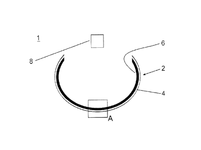
Figure 1 shows a section through an exemplary embodiment of
the apparatus 1 according to the invention for carrying out
the method according to the invention for producing and for
fusing ultra-dense hydrogen.
The apparatus 1 according to the exemplary embodiment
consists of a cavity 2 which is open in places for receiving
a gas. The gas here is preferably a hydrogen gas in its
molecular form exposed to negative pressure, which is
immediately converted into an atomic plasma in the cavity 2.
The cavity 2 is a pore of an open-pore metal foam or ceramic
foam 4. The material of the metal foam or ceramic foam 4
should be selected in this case so that even whilst
delivering the highest possible energy during a fusion, the
material does not change its alpha lattice state or if this
is changed, the alpha lattice state is achieved again.
CA 02923912 2016-03-15
- 12 -
According to the exemplary embodiment, the pore of the metal
foam 4 is at least partially provided with a catalyst
coating 6 in the inner side. The catalyst coating 6 here has
a granular structure and according to the exemplary
embodiment, contains titanium oxide. The catalyst coating
can also be constructed of Fe203, Ni, MnO and other
materials which can be applied to the metal foam or the
ceramic foam as a thin perturbed regular lattice structure
having a layer thickness of 10 nm to 4 pm.
Furthermore, the apparatus 1 has an initiating source 8
which can trigger a fusion process in a cavity 2. According
to the exemplary embodiment shown, the initiating source 8
is a source of coherent, monochromatic light 8 which can act
upon the cavity 2 with electromagnetic radiation. The
initiation is accomplished by the thermal radiation of the
cavity walls where due to resonance effects with the walls
now mirror-coated by the superfluid hydrogen, preferred
wavelengths or frequencies occur with high field intensity.
The repulsive potential between protons is very high. The
protons are the nuclei of the hydrogen. They undergo their
repulsion due to their positive charge (Coulomb repulsion).
In ultra-dense hydrogen the nuclei are very tightly packed
and therefore very close. The repulsive potential of the
nuclei is reduced here by the spherical expansion of the
charge and matter cloud of the proton. Furthermore, this
repulsion is very severely reduced by other forces such as
strong interaction, weak interaction and gravitation and by
the shielding of electron states. If ultra-dense hydrogen 12
is formed, the density is very high and the fusion partners,
here hydrogen atoms 12, are therefore close to the fusion
barrier. Accordingly a small energy contribution is already
sufficient to initiate a fusion. According to the exemplary
embodiment, such an ignition of the fusion process is either
executed by a coherent monochromatic light source 8 or by
the natural black body radiation of the cavity 2 but can
also be accomplished by external ionization, for example, by
CA 02923912 2016-03-15
- 13 -
high voltage. Alternatively a simple spark plug can also be
used as initiating source 8 for this purpose.
Figure 2 shows an enlarged view of the section A from Figure
1. In particular, the granular structure of the catalyst
coating 6 is illustrated here. As a result, a Casimir
geometry is created with a plurality of cavities 10 which
exert capillary and/or Casimir forces on matter. Thus,
corresponding forces can also act on a molecular hydrogen
introduced into the cavity 2. Furthermore, the "Purcell
Effect" is known for such structures, which amplifies
electromagnetic processes many times.
Figure 3 shows a further enlargement of the structure from
the exemplary embodiment of the apparatus 1 according to the
invention of section B from Figure 2. Here it is illustrated
that the granular structure of the catalyst coating 6 splits
molecular hydrogen into atomic hydrogen and this then
condenses into ultra-dense hydrogen 12 in the cavities 10 or
the Casimir geometries 10. This corresponds to a charged
state of the apparatus 1.
The method according to the invention for generating and
fusing ultra-dense hydrogen is explained hereinafter. Figure
4 shows a schematic view of a charging process of the
apparatus 1 according to the method according to the
invention. In this case, a gas (reference number 14) is
introduced into the cavity 2, which is to be catalyzed and
condensed. According to the exemplary embodiment, the gas is
molecular hydrogen. Through contact of the hydrogen gas with
the catalyst coating 6, the energy required for a plasma
formation and also for a condensate formation is reduced to
such an extent (reference number 16) that this can take
place spontaneously at room temperature and even lower
temperatures. According to the exemplary embodiment, the
condensate is atomic hydrogen which has been catalytically
split. The atomic hydrogen then condense (reference number
CA 02923912 2016-03-15
- 14 -
20) in the Casimir geometry and becomes embedded in the
catalyst coating 6 and is thus present in condensed form as
ultra-dense hydrogen 12.
Figure 5 shows a possible fusion process according to the
method according to the invention. An apparatus 1 charged
for example according to Figure 4 is assumed. An embedded
(reference number 20) condensed ultra-dense hydrogen 12 is
excited energetically by an initiating source 8. The
condensed hydrogen forms clusters 12. These lie tightly
squeezed together and between the heavy catalyst particles
7. The hydrogen protons are very tightly packed - the
packing density being obtained from the quantum-mechanical
state of the binding electrons in cooperation with the
protons. The near field of the catalyst particles 7 assists
the condensation. The packing density of the protons lies
within the critical density for penetration of the fusion
barrier. The energy contribution 22 from the initiating
source 8 thus induces a fusion process 24 of the ultra-dense
hydrogen. In particular helium, which can volatilize from
the catalyst coating 6, is formed by the fusion process 24.
In addition to helium, reaction energy 26 in the form of
heat is produced. This reaction energy 26 is then guided out
from the apparatus 1 via the metal foam/ceramic foam 4 by
means of heat conduction and at the surface thereof by means
of thermal radiation (reference number 28) or is guided into
adjacent regions of the apparatus. The reaction energy 26
can thus be used, for example, for the ignition of fusion in
neighbouring apparatuses. Furthermore, the reaction energy,
in particular reaction heat, can also be converted
conventionally into mechanical, chemical or electrical
energy and utilized.
Disclosed is a method for generating 18 and for fusing 24
ultra-dense hydrogen 12 in which molecular hydrogen is fed
into 14 at least one cavity 2 and catalyzed 16, where a
condensation 18 of the molecular hydrogen is initiated on a
CA 02923912 2016-03-15
- 15 -
catalyst 6 of the cavity 2 to form an ultra-dense hydrogen,
the ultra-dense hydrogen 12 is exposed to negative pressure
or electromagnetic radiation to initiate 22 fusion 24 of the
ultra-dense hydrogen 12 in the at least one cavity 2 and the
reaction heat 26 is led out from the at least one cavity 2.
Furthermore, an apparatus 1 for carrying out the method is
disclosed.
CA 02923912 2016-03-15
- 16 -
REFERENCE LIST
1 Apparatus
2 Cavity
4 Metal foam
6 Catalyst coating
7 Catalyst particle of the catalyst coating
8 Initiating source/laser
Cavity/Casimir geometry
10 12 Embedded ultra-dense hydrogen
14 Introduction of a fluid
16 Catalysis
18 Condensation
20 Embedding
22 Initiating energy
24 Fusion process
26 Reaction energy
28 Guiding out the reaction energy