Note: Descriptions are shown in the official language in which they were submitted.
LENTICULAR AIRSHIP AND ASSOCIATED CONTROLS
TECHNICAL FIELD
[003] The disclosure is related to lenticular airships. In particular, the
disclosure relates to an
airship and associated controls for providing enhanced maneuverability and
operability.
BACKGROUND INFORMATION
[004] Aerostatic lighter-than-air airships have seen substantial use since
1783 following the
first successful manned flight of the Montgolfier brothers hot air balloon.
Numerous
improvements have been made since that time, but the design and concept of
manned hot air
balloons remains substantially similar. Such designs may include a gondola for
carrying an
operator and passengers, a heating device (e.g., a propane torch), and a large
envelope or bag
affixed to the gondola and configured to be filled with air. The operator may
then utilize the
heating device to heat the air until the buoyant forces of the heated air
exert sufficient force on
the envelope to lift the balloon and an attached gondola. Navigation of such
an airship has
proven to be difficult, mainly due to wind currents and lack of propulsion
units for directing the
balloon.
[005] To improve on the concept of lighter-than-air flight, some lighter-than-
air airships have
evolved to include propulsion units, navigational instruments, and flight
controls. Such additions
may enable an operator of such an airship to direct the thrust of the
propulsion units in such a
direction as to cause the airship to proceed as desired. Airships utilizing
propulsion units and
navigational instruments
CAN_DMS: \10798533511 - 1 -
CA 2924142 2017-07-18
CA 02924142 2016-03-17
WO 2009/023114 PCT/US2008/009453
typically do not use hot air as a lifting gas (although hot air may be used),
with
many operators instead preferring lighter-than-air lifting gases such as
hydrogen
and helium. These airships may also include an envelope for retaining the
lighter-
than-air gas, a crew area, and a cargo area, among other things. The airships
are
typically streamlined in a blimp- or zeppelin-like shape (also known as
"cigar"
shaped), which, while providing reduced drag, may subject the airship to
adverse
aeronautic effects (e.g., weather cocking and reduced maneuverability).
[006] Airships other than traditional hot air balloons may be divided into
several
classes of construction: rigid, semi-rigid, non-rigid, and hybrid type. Rigid
airships
typically possess rigid frames containing multiple, non-pressurized gas cells
or
balloons to provide lift. Such airships generally do not depend on internal
pressure
of the gas cells to maintain their shape. Semi-rigid airships generally
utilize some
pressure within a gas envelope to maintain their shape, but may also have
frames
along a lower portion of the envelope for purposes of distributing suspension
loads
into the envelope and for allowing lower envelope pressures, among other
things.
Non-rigid airships typically utilize a pressure level in excess of the
surrounding air
pressure in order to retain their shape, and any load associated with cargo
carrying
devices is supported by the gas envelope and associated fabric. The commonly
used blimp is an example of a non-rigid airship.
[007] Hybrid airships may incorporate elements from other airship types,
such as
a frame for supporting loads and an envelope utilizing pressure associated
with a
lifting gas to maintain its shape. Hybrid airships also may combine
characteristics
of heavier-than-air airship (e.g., airplanes and helicopters) and lighter-than-
air
technology to generate additional lift and stability. It should be noted that
many
airships, when fully loaded with cargo and fuel, may be heavier than air and
thus
may use their propulsion system and shape to generate aerodynamic lift
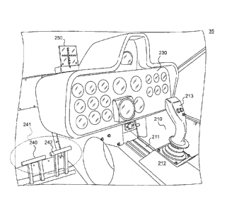
necessary
to stay aloft. However, in the case of a hybrid airship, the weight of the
airship and
cargo may be substantially compensated for by lift generated by forces
associated
with a lifting gas such as, for example, helium. These forces may be exerted
on the
envelope, while supplementary lift may result from aerodynamic lift forces
associated with the hull.
- 2 -
CA 02924142 2016-03-17
WO 2009/023114 PC T/US 2008/009453
[008] A lift force (i.e., buoyancy) associated with a lighter-than-air gas
may
depend on numerous factors, including ambient pressure and temperature, among
other things. For example, at sea level, approximately one cubic meter of
helium
may balance approximately a mass of one kilogram. Therefore, an airship may
include a correspondingly large envelope with which to maintain sufficient
lifting gas
to lift the mass of the airship. Airships configured for lifting heavy cargo
may utilize
an envelope sized as desired for the load to be lifted.
[009] Hull design and streamlining of airships may provide additional lift
once the
airship is underway. For example, a lenticular airship may have a discus-like
shape
in circular planform where the diameter may be greater than an associated
height.
Therefore, the weight of an airship may be compensated by the aerodynamic lift
of
the hull and the forces associated with the lifting gas including, for
example, helium.
[010] However, a lighter-than-air airship may present unique problems
associated with aerodynamic stability, based on susceptibility to adverse
aerodynamic forces. For example, traditional airships may typically exhibit
low
aerodynamic stability in the pitch axis. Lenticular shaped bodies may be
aerodynamically less stable than either spherical or ellipsoidal shaped
bodies. For
example, the boundary layer airflow around the body may separate and create
significant turbulence at locations well forward of the trailing edge.
Therefore,
systems and methods enhancing aerodynamic stability may be desirable.
[011] Further, increasing flight controllability may be another challenging
but
important aspect for lighter-than-air airship design. For example, the airship
may
be lifted by thrust forces generated by vertically-directed propulsion
engines, and
may move forward or backwards powered by thrust forces generated by
horizontally-directed propulsion engines. In traditional airship flight
control systems,
however, propeller pitch has not been variably adjustable. Therefore, the
operator
of such airships could not control a pitch angle and/or a lift force, among
other
things, associated with the airship through adjustment of propeller pitch.
Further,
vertically- and horizontally-directed propulsion engines have been separately
controlled, without provision for coordination of these engines with
horizontal and
vertical stabilizer systems. Therefore, traditional airship controls have not
provided
maneuverability and response desired by operators. In addition, the operator
may
- 3 -
CA 02924142 2016-03-17
WO 2009/023114 PCT/US2008/009453
wish to know certain flight-related parameters during the flight without
having to
look away from the view ahead of the airship, to provide more effective
control
input. For example, the operator may desire an indication of the attitude of
the
airship to be viewable directly in line of sight (LOS) through a gondola
canopy
before providing pitch/roll control inputs to the airship. Accordingly,
systems and
methods for enhancing flight controllability including but not limited to,
airship pitch
and yaw control, coordination of one or more control systems, and/or
indication of
certain airship status parameters, may be desirable.
[012] The present disclosure may be directed to addressing one or more of the
desires discussed above utilizing various exemplary embodiments of an airship.
SUMMARY OF THE DISCLOSURE
[013] In one aspect, the present disclosure is directed to a system for
controlling
yaw associated with an airship. The system may include one or more vertical
control surfaces associated with an airship, a first power source and a second
power source, each configured to provide a thrust associated with an airship,
and a
yaw control configured to receive an input indicative of a desired yaw angle.
The
system may further include a controller communicatively connected to the yaw
control, the one or more vertical control surfaces, and the first and second
power
sources. The controller may be configured to receive an output signal from the
yaw
control corresponding to the desired yaw angle. The controller may be further
configured to generate a control signal configured to modify a state
associated with
at least one of the one or more vertical control surfaces, the first power
source, and
the second power source, such that the airship substantially attains the
desired yaw
angle.
[014] In another aspect, the present disclosure is directed to a method for
controlling yaw associated with an airship including a first power source, a
second
power source, and a vertical control surface. The method may include receiving
a
signal indicative of a desired yaw angle for the airship and determining an
operational state associated with the first power source, the second power
source,
and the vertical control surface. The method may further include modifying the
- 4 -
CA 02924142 2016-03-17
WO 2009/023114 PCT/US2008/009453
operational state associated with the first power source, the second power
source,
and the vertical control surface to cause airship to attain the desired yaw
angle.
[015] In yet another aspect, the present disclosure is directed to a system
for
controlling yaw associated with a lenticular airship defining a periphery and
a nose.
The system may include a vertical control surface associated with an empennage
of the lenticular airship, a first power source located on the periphery of
the
lenticular airship at a position 120 degrees from the nose and configured to
provide
a thrust associated with the lenticular airship, and a second power source
located
on the periphery of the lenticular airship at a position negative 120 degrees
from
the nose and configured to provide a thrust associated with the lenticular
airship.
The system may further include a pedal actuated yaw control configured to
receive
an input indicative of a desired yaw angle. The system may also include a
controller communicatively connected to the yaw control, the vertical control
surface, and the first and second power sources. The controller may be
configured
to receive an output signal from the yaw control corresponding to the desired
yaw
angle. The controller may be further configured to generate a control signal
configured to modify a state associated with at least one of the one or more
vertical
control surfaces, the first power source, and the second power source, such
that
the lenticular airship substantially attains the desired yaw angle.
[016] According to a further aspect, the present disclosure is directed to
a
system for controlling a flight parameter associated with an airship. The
system
may include a frame, and a support structure slidably mounted to the frame and
configured to provide support to an airship control and a slider output signal
indicative of an offset of the support structure from a predetermined neutral
position
of the frame. The system may further include a processor communicatively
connected to the frame, the support structure, and airship control. The
processor
may be configured to receive the slider output signal, wherein the processor
is
configured to generate a control signal for modifying the flight parameter
based on
the slider output signal.
[017] According to a further aspect, the present disclosure is directed to
a
method for controlling at least one parameter associated with an airship. The
method may include sliding a support structure upon a frame, the support
structure
- 5 -
CA 02924142 2016-03-17
WO 2009/023114 PCT/US2008/009453
being configured to provide a slider output signal indicative of an offset of
the
support structure from a predetermined neutral position and including a
control.
The method may further include receiving the slider output signal at a
controller,
and generating a control signal based on the slider output signal; and
modifying a
flight parameter associated with the airship via the control signal.
[018] In yet another aspect, the present disclosure is directed to a system
for
controlling a propeller pitch associated with each of three or more propulsion
assemblies associated with an airship. The system may include a control
configured to receive an input from an operator indicative of a desired lift
force.
The system may further include a processor configured to receive a signal
indicative of the desired lift force from the control and generate an output
signal for
causing a substantially similar modification to operation of each of the three
or more
propulsion assemblies, such that the desired lift force is substantially
applied to the
airship.
[019] In yet another aspect, the present disclosure is directed to a method
for
controlling propeller pitch related to three or more propulsion assemblies
associated with an airship. The method may include receiving an input from an
operator indicative of a desired lift force, and modifying operation of the
three or
more propulsion assemblies, such that the desired lift force is substantially
applied
to the airship.
[020] In yet another aspect, the present disclosure is directed to a system
for
controlling a lift force associated with an airship. The system may include
three
propulsion assemblies, each propulsion assembly including a variable pitch
propeller, and a control configured to receive an input from an operator
indicative of
a desired lift force. The system may further include a processor
communicatively
connected to the three propulsion assemblies and the control. The processor
may
be configured to receive a signal indicative of the desired lift force from
the control,
and transmit a control signal to the three propulsion assemblies configured to
cause each of the three propulsion assemblies to produce a substantially
similar
thrust vector.
[021] In yet another aspect, the present disclosure is directed to a system
for
displaying attitude information associated with an airship. The system may
include
-6.
a first plurality of indicators arranged along a horizontal axis, and a second
plurality
of indicators arranged along a vertical axis. The system may include a
processor
configured to determine an attitude associated with the airship; and cause at
least
one indicator of the first plurality of indicators or the second plurality of
indicators to
respond based on the attitude.
[022] In yet another aspect, the present disclosure is directed to a method
for
displaying attitude information associated with an airship. The method may
include
receiving a signal indicative of an attitude associated with the airship, and
determining an attitude associated with the airship based on the signal. The
method may further include causing at least one indicator of a first plurality
of
indicators and a second plurality of indicators to respond according to the
attitude.
[023] In yet another aspect, the present disclosure is directed to a system
for
displaying attitude information associated with an airship. The system may
include
a sensor configured to sense an attitude associated with the airship and
generate a
corresponding sensor output, and a substantially transparent display. The
system
may further include a first plurality of indicators arranged along a
horizontal axis of
the display, and a second plurality of indicators arranged along a vertical
axis of the
display. The system may also include a processor configured to determine an
attitude associated with the airship based on the sensor output, and cause at
least
one indicator of the first plurality of indicators or the second plurality of
indicators to
light according to the attitude.
[023a] Certain exemplary embodiments can provide a system for controlling yaw
associated with an airship, the system comprising: one or more vertical
control
surfaces associated with the airship; a first power source and a second power
source, each configured to provide a thrust associated with the airship; a yaw
control configured to receive an input indicative of a desired yaw angle; and
a
controller communicatively connected to the yaw control, the one or more
vertical
control surfaces, and the first and second power sources, wherein the
controller is
configured to: receive an output signal from the yaw control corresponding to
the
desired yaw angle; generate a control signal configured to modify a state
associated with at least one of the one or more vertical control surfaces, the
first
- 7 -
CA 2924142 2019-03-04
power source, and the second power source, such that the airship substantially
attains the desired yaw angle; receive information indicative of current
characteristics related to the current flight of the airship; compare the
current
characteristics with a predetermined set of preferred characteristics; and
automatically generate the control signal based on the comparison.
[023b] Certain exemplary embodiments can provide a method for controlling yaw
associated with an airship including a first power source, a second power
source,
and a vertical control surface, the method comprising: receiving, from a yaw
control,
a signal indicative of a desired yaw angle for the airship; determining an
operational
state associated with the first power source, the second power source, and the
vertical control surface; and modifying the operational state associated with
the first
power source, the second power source, and the vertical control surface to
cause
the airship to attain the desired yaw angle; receiving information indicative
of
current characteristics related to the current flight of the airship;
comparing the
current characteristics with a predetermined set of preferred characteristics;
and
automatically generating the control signal based on the comparison.
[023c] Certain exemplary embodiments can provide a system for controlling yaw
associated with a lenticular airship defining a nose and a periphery, the
system
comprising: a vertical control surface associated with an empennage of the
lenticular airship; a first power source located on the periphery of the
lenticular
airship at a position 120 degrees from the nose and configured to provide a
thrust
associated with the airship; a second power source located on the periphery of
the
lenticular airship at a position negative 120 degrees from the nose and
configured
to provide a thrust associated with the lenticular airship; a pedal actuated
yaw
control configured to receive an input indicative of a desired yaw angle; and
a
controller communicatively connected to the yaw control, the vertical control
surface, and the first and second power sources, wherein the controller is
configured to, receive an output signal from the yaw control corresponding to
the
desired yaw angle; generate a control signal configured to modify a state
associated with the vertical control surface, the first power source, and the
second
power source, such that the lenticular airship substantially attains the
desired yaw
- 7a -
CA 2924142 2019-03-04
angle; receive information indicative of current characteristics related to
the current
flight of the airship; compare the current characteristics with a
predetermined set of
preferred characteristics; and automatically generate the control signal based
on
the comparison.
BRIEF DESCRIPTION OF THE FIGURES
[024] Fig. 1 is a perspective schematic view of an exemplary embodiment of a
lenticular airship (LA);
[025] Fig. 2 is a schematic view highlighting an exemplary empennage and its
exemplary horizontal control surfaces and vertical control surfaces;
[026] Fig. 3A is a schematic, partial perspective view of an exemplary
embodiment
of a vertical propulsion assembly;
[027] Fig. 3B is a schematic, partial perspective view of an exemplary
embodiment of a thrust propulsion assembly;
- 7b -
CA 2924142 2019-03-04
CA 02924142 2016-03-17
WO 2009/023114 PCT/US2008/009453
[028] Fig. 4A is a schematic, plan, bottom-side view of an exemplary
embodiment of an arrangement of propulsion systems associated with an
exemplary LA;
[029] Fig. 4B is a schematic, plan, bottom-side view of another exemplary
embodiment of an arrangement of propulsion systems associated with an
exemplary LA;
[030] Fig. 5A is a schematic, partial perspective view of an exemplary
gondola
associated with an exemplary LA, showing an exemplary slider control and an
exemplary collective pitch control;
[031] Fig. 5B is another schematic, partial perspective view of an
exemplary
gondola associated with an exemplary LA, showing an exemplary slider control
and
an exemplary collective pitch control;
[032] Fig. 5C is another schematic, partial perspective view of an
exemplary
gondola associated with an exemplary LA, showing an exemplary slider
control,.an
exemplary yaw control, and an exemplary attitude indicator;
[033] Fig. 6 is a schematic, front-side view of an exemplary embodiment of
an
attitude indicator;
[034] Fig. 7 is a block diagram of an exemplary embodiment of a flight
computer;
[035] Fig. 8 is a block diagram depicting an exemplary embodiment of a
method
for controlling yaw associated with an airship;
[036] Fig. 9 is a block diagram depicting an exemplary embodiment of a
method
for controlling at least one parameter associated with an airship;
[037] Fig. 10 is a block diagram depicting an exemplary embodiment of a
method for controlling propeller pitch related to three or more propulsion
assemblies associated with an airship; and
[038] Fig. 11 is a block diagram depicting an exemplary embodiment of a
method for displaying attitude information associated with an airship.
DETAILED DESCRIPTION
[039] Fig. 1 illustrates one exemplary embodiment of a lenticular airship
(LA) 10.
LA 10 may be configured for vertical take-off and landing (VTOL) as well as
navigation in three dimensions (e.g., X, Y, and Z planes). To facilitate such
a flight,
- 8 -
CA 02924142 2016-03-17
WO 2009/023114 PCT/US2008/009453
LA 10 may include a support structure 20, a hull 22, an empennage assembly 25,
rear landing gear assemblies 377, a propulsion system including propulsion
assemblies 31, a gondola 35, one or more computers 600 (see, e.g., Fig. 7),
and/or
a front landing gear assembly 777. Throughout this discussion of various
embodiments, the terms "airship" and ''lenticular airship" may be used
interchangeably to refer to various embodiments of LA 10. Further, the terms
"front" and/or "fore" may be used to refer to areas within a hemisphere
section of LA
closest to forward travel, and the term "rear" and/or "aft" may be used to
refer to
areas within a hemisphere section of LA 10 closest to the opposite direction
of
travel. Moreover, the term "tail'' may be used to refer to a rear most point
associated with hull 22, while the term "nose" may be used to refer to the
forward
most point within the front section of hull 22.
[040] Support structure 20 may be configured to define a shape associated
with
LA 10, while providing support to numerous systems associated with LA 10. Such
systems may include, for example, hull 22, gondola 35, a cargo compartment
(not
shown), and/or propulsion assemblies 31. Support structure 20 may be defined
by
one or more frame members interconnected to form a desired shape. For example,
according to some embodiments, frame members at the bottom part of support
structure 20 may form a bisected "H" configuration of built up graphite
composite
beams. For example, the frame members may be an assembly of 3-ply graphite
fabric layers applied at 60 degree angles between each ply. These frame
members
may join with a similarly constructed rigid ring that defines the outer
circumference
of LA 10. The ring may be composed of a plurality of laid up composite
structures
that are joined together with a channel-shaped composite stiffener. Such an
arrangement of the beams and the rigid ring frame may work together to carry
static
and dynamic loads in both compression and tension.
[041] To maximize a lifting capacity associated with LA 10, it may be
desirable to
design and fabricate support structure 20 such that weight associated with
support
structure 20 is reduced or minimized while strength, and therefore resistance
to
aerodynamic forces, for example, is increased or maximized. In other words,
maximizing a strength-to-weight ratio associated with support structure 20 may
provide a more desirable configuration for LA 10. For example, one or more
frame
- 9 -
CA 02924142 2016-03-17
WO 2009/023114 PCT/US2008/009453
members may be constructed from light weight, but high strength, materials
including, for example, a substantially carbon-based material (e.g., carbon
fiber)
and/or aluminum, among other things.
[042] According to some embodiments, one or more frame members may be
constructed, to include a carbon fiber/resin composite and honeycomb-carbon
sandwich. The honeycomb-carbon sandwich may further include a carbon mousse
or foam type material. In such an embodiment, individual frame members
associated with support structure 20 may be fabricated in an appropriate size
and
shape for assembly within support structure 20. Such construction may lead to
a
desirable strength-to-weight ratio for support structure 20. In some
embodiments, it
may be desirable to fabricate support structure 20 such that an associated
mass is
less than, for example, 200 kilograms.
[043] Hull 22 may include multiple layers/envelopes and/or may be of a semi-
rigid construction. Further, hull 22 may be substantially oblate spheroid, or
"lenticular" in shape. For example, the dimensions of an oblate spheroid shape
may be approximately described by the representation A = B > C, where A is a
length dimension (e.g., along roll axis 5); B is a width dimension (e.g.,
along pitch
axis 6); and C is a height dimension (e.g., along yaw axis 7) of an object. In
other
words, an oblate spheroid may have an apparently circular planform with a
height
(e.g., a polar diameter) less than the diameter of the circular planform
(e.g., an
equatorial diameter). For example, according to some embodiments, hull 22 may
include dimensions as follows: A = 21 meters; B = 21 meters; and C = 7 meters.
Dimensions associated with hull 22 may also define, at least in part, a volume
of
lighter-than-air gas that may be retained within hull 22. For example, using
the
dimensions given above for hull 22, an uncompressed internal volume associated
with hull 22 may be approximately 1275 cubic meters. Note that these
dimensions
are exemplary only and larger or smaller dimensions may be implemented without
departing from the scope of the present inventions. For example, hull 22 may
include dimensions as follows, A = 105 meters; B = 105 meters, and C = 35
meters.
[044] Hull 22 may be configured to retain a volume of lighter-than-air gas
and
may be fabricated such that, upon retention of the volume of gas, a
substantially
- 10-
CA 02924142 2016-03-17
WO 2009/023114 PCT/1JS2008/009453
lenticular and/or oblate spheroid shape results. Therefore, hull 22 may
include a
first envelope sewn or otherwise assembled of fabric or material configured to
retain a lighter-than-air gas and/or having a circular planform with a maximum
thickness less than the diameter of the circular planform. In some
embodiments,
the first envelope may be fabricated from materials including, for example,
aluminized plastic, polyurethane, polyester, laminated latex, and any other
material
suitable for retaining a lighter-than-air gas. The first envelope may be
fabricated
from one or more polyester sheets and may be sewn or otherwise shaped such
that
retention of a volume of lighter-than-air gas causes first envelope 282 to
assume
the shape of an oblate spheroid.
[045] The first envelope associated with hull 22 may be configured to be
fastened to support structure 20 such that support structure 20 may provide
support
to hull 22. For example, the first envelope may be attached to the rim of the
composite load ring to provide a continuous and smooth attachment of the upper
fabric skin to LA 10. Such a design may eliminate stress concentrations caused
by
asymmetrical upward forces frequently encountered in conventional airship
designs. In some embodiments, the fabric seams on LA 10 may run radially from
the center of the helium dome to the rigid rim so that the seams can carry
loads
along their length.
[046] Lighter-than-air lifting gasses for use within the first envelope of
hull 22
may include, for example, helium, hydrogen, methane, and ammonia, among
others. The lift force potential of a lighter-than-air gas may depend on the
density
of the gas relative to the density of the surrounding air or other fluid
(e.g., water).
For example, the density of helium at 0 degrees Celsius and 101.325 kilo-
Pascals
may be approximately 0.1786 grams/liter, while the density of air at 0 degrees
C
and 101.325 kilo-Pascals may be approximately 1.29 g/L. Based on the lighter-
than-air gas chosen, an internal volume of the first envelope associated with
hull 22
may be selected such that a desired amount of lift force is generated by a
volume
of lighter-than-air gas.
[047] According to some embodiments, the first envelope associated with
hull 22
may be divided by a series of "walls" or dividing structures (not shown).
These
walls may create separated "compartments" that may each be filled individually
with
- 11 -
CA 02924142 2016-03-17
WO 2009/023114 PCT/US2008/009453
a lighter-than-air lifting gas. Such a configuration may mitigate the
consequences
of the failure of one or more compartments (e.g., a leak or tear in the
fabric) such
that LA 10 may still possess some aerostatic lift upon failure of one or more
compartments. In some embodiments, each compartment may be in fluid
communication with at least one other compartment, and such walls may be
fabricated from materials similar to those used in fabrication of the first
envelope,
or, alternatively (or in addition), different materials may be used. For
example, the
"walls" may be constructed by a material that is sufficiently porous to allow
the gas
to slowly migrate between the separate cells to maintain an equal pressure.
[048] One or more of the compartments within the first envelope may include
one or more fill and/or relief valves (not shown) configured to allow filling
of the first
envelope, which may result in minimizing the risk of over-inflation of the
first
envelope. Such valves may be designed to allow entry of a lighter-than-air gas
as
well as allowing a flow of lighter-than-air gas to flow out of the first
envelope upon
an internal pressure reaching a predetermined value (e.g., about 150 to about
400
Pascals).
[049] In addition to aerostatic lift generated by retention of a lighter-
than-air gas,
hull 22 may be configured to generate at least some aerodynamic lift when
placed
in an airflow (e.g., LA 10 in motion and/or wind moving around hull 22) based
on an
associated angle of attack and airflow velocity relative to LA 10. For
example, hull
22 may include a second envelope configured to conform substantially to a
shape
associated with the first envelope. The second envelope associated with hull
22
may, for example, substantially surround both top and bottom surfaces of the
first
envelope, or alternatively, the second envelope may be formed by two or more
pieces of material, each substantially covering only a portion of the top
and/or
bottom surface of hull 22. For example, according to some embodiments, the
second envelope may closely resemble the first envelope, but contain a
slightly
larger.yolume, such that the second envelope may substantially surround
support
structure 20 and the first envelope associated with hull 22.
[0.0] The second
envelope may include canvass, vinyl, and/or other suitable
material that may be sewn or otherwise crafted into a suitable shape, which
may
possess a desired resistance to external stresses (e.g., tears, aerodynamic
forces,
-12-
CA 02924142 2016-03-17
WO 2009/023114 PCT/US2008/009453
etc.). In some embodiments, the second envelope may include a low drag and/or
low weight fabric such as, for example, polyester, polyurethane, and/or
DuPont."'
Tedlar0, having a thermo plastic coating.
[051] In addition to providing aerodynamic lift force transfer to support
structure
20 and potential tear resistance, upon installation of the second envelope, a
space
may be created between the first envelope and the second envelope, which may
be
utilized as a ballonet for LA 10. For example, a ballonet may be used to
compensate for differences in pressure between a lifting gas within the first
envelope and the ambient air surrounding LA 10, as well as for the ballasting
of an
airship. The ballonet may therefore allow hull 22 to maintain its shape when
ambient air pressure increases (e.g., when LA 10 descends). Pressure
compensation may be accomplished, for example, by pumping air into, or venting
air out of, the ballonet as LA 10 ascends and descends, respectively. Such
pumping and venting of air may be accomplished via air pumps, vent tabs, or
other
suitable devices (e.g., action of the propulsion system 30) associated with
hull 22.
[052] Fig. 1 further illustrates various axes relative to the exemplary LA
10 for
reference purposes. LA 10 may define a roll axis 5, a pitch axis 6, and a yaw
axis
7. Roll axis 5 of LA 10 may correspond with an imaginary line running through
hull
22 in a direction from, for example, empennage assembly 25 to gondola 35. Yaw
axis 7 of LA 10 may correspond with an imaginary line running perpendicular to
roll
axis 5 through hull 22 in a direction from, for example, a bottom surface of
hull 22 to
a top surface of hull 22. Pitch axis 6 may correspond to an imaginary line
running
perpendicular to both yaw and roll axes, such that pitch axis 6 runs through
hull 22
from one side of LA 10 to the other side of LA 10. "Roll axis" and "X axis;"
"pitch
axis" and "Y axis;" and "yaw axis" and "Z axis" may be used interchangeably
throughout this discussion to refer to the various axes associated with LA 10.
One
of ordinary skill in the art will recognize that the terms described in this
paragraph
are exemplary only and not intended to be limiting.
[053] Yaw and pitch controls of LA 10 may determine the vertical and
horizontal
directions of propulsion, and ultimately determine the flight direction of LA
10.
[054] Fig. 2 illustrates an exemplary empennage assembly 25. Empennage
assembly 25 may be configured to provide stabilization and/or navigation
-13-
CA 02924142 2016-03-17
WO 2000/023114 PCT/US2008/009453
functionality to LA 10. Empennage assembly 25 may be operatively connected to
support structure 20 (see Fig. 1) via brackets, mounts, and/or other suitable
methods. For example, in some embodiments, empennage 25 may be mounted to
a keel hoop 120, and a longitudinal support member 124 associated with support
structure 20, utilizing empennage mount 345. As shown in Fig. 2, keel hoop 120
may be a substantially circular peripheral beam associated with support
structure
20. Keel hoop 120 may include one or more frame sections with a defined radius
of curvature that may be affixed to one another to form keel hoop 120 of a
desired
radius. In some embodiments, keel hoop 120 may have a diameter of, for
example,
approximately 21 meters. Longitudinal frame member 124 may be configured to
extend in a longitudinal direction from a fore portion of keel hoop 120 to a
rear
portion of keel hoop 120. Longitudinal frame member 124 may meet keel hoop 120
substantially orthogonally and may be aligned at substantially a midway point
associated with keel hoop 120. In other words, viewing keel hoop 120 in a two
dimensional plane, longitudinal frame member 124 may intersect keel hoop 120
at
relative positions of 0 degrees and 180 degrees. One of ordinary skill in the
art will
recognize that numerous other mounting configurations may be utilized and are
intended to fall within the scope of the present disclosure.
[055] According to some embodiments, empennage assembly 25 may include a
vertical stabilizing member 310. Vertical stabilizing member 310 may be
configured
as an airfoil to provide LA 10 with stability and assistance in yaw/linear
flight
control. Vertical stabilizing member 310 may include a leading edge, a
trailing
edge, a pivot assembly, one or more spars, and one or more vertical control
surfaces 350 (e.g., a rudder).
[056] Vertical stabilizing member 310 may be pivotally affixed to a point
on
empennage assembly 25. During operation of LA 10, vertical stabilizing member
310 may be directed substantially upward from a mounting point of empennage
assembly 25 to support structure 20 while the upper-most point of vertical
stabilizing member 310 remains below or substantially at the same level as the
uppermost point on the top surface of hull 22. Such a configuration may allow
vertical stabilizing member 310 to maintain isotropy associated with LA 10.
Under
certain conditions (e.g., free air docking, high winds, etc.), vertical
stabilizing
- 14 -
CA 02924142 2016-03-17
WO 2009/023114 PCT/US2008/009453
member 310 may be configured to pivot about a pivot assembly within a vertical
plane such that vertical stabilizing member 310 comes to rest in a horizontal
or
downward, vertical direction, and substantially between horizontal stabilizing
members 315. Such an arrangement may further enable LA 10 to maximize
isotropy relative to a vertical axis, thereby minimizing the effects of
adverse
aerodynamic forces, such as wind cocking with respect to vertical stabilizing
member 310. In some embodiments consistent with the present disclosure, where
hull 22 includes a thickness dimension of 7 meters and where empennage
assembly 25 is mounted to keel hoop 120 and longitudinal frame member 124,
vertical stabilizing member 310 may have a height dimension ranging from about
3
meters to about 4 meters.
[057] Vertical stabilizing member 310 may include one or more spars (not
shown) configured to define the planform of vertical stabilizing member 310 as
well
as provide support for a skin associated with vertical stabilizing member 310.
The
one or more spars may include a substantially carbon-based material, such as,
for
example, a carbon fiber honeycomb sandwich with a carbon fiber mousse. Each of
the one or more spars may have openings (e.g., circular cutouts) at various
locations, such that weight is minimized, with minimal compromise in strength.
One
of ordinary skill in the art will recognize that minimizing the number of
spars used,
while still ensuring desired structural support may allow for minimizing
weight
associated with vertical stabilizing member 310. Therefore, the one or more
spars
may be spaced along the span of vertical stabilizing member 310 at a desired
interval configured to maximize support while minimizing weight.
[058] A leading edge 322 may be utilized for defining an edge shape of
vertical
stabilizing member 310 as well as securing the spars prior to installation of
a skin
associated with vertical stabilizing member 310. Leading edge 322 may also
include a substantially carbon-based material, such as a carbon fiber
honeycomb
sandwich with a carbon fiber mousse.
[059] Leading edge 322 and the one or more spars may be aligned and fastened
in place with a skin installed substantially encasing leading edge 322 and
spars.
The skin may include, for example, canvass, polyester, nylon, thermoplastics,
and/or any other suitable material. The skin may be secured using adhesives,
-15-
CA 02924142 2016-03-17
WO 2009/023114 PC l'/US2008/009453
shrink wrap methods, and/or any other suitable method for securing the skin to
leading edge 322 and the one or more spars.
[060] For example, in some embodiments, a canvass material may be applied
over the one or more spars and leading edge 322 then secured using an adhesive
and/or other suitable fastener. The canvass material may then be coated with a
polyurethane and/or thermoplastic material to further increase strength and
adhesion to the one or more spars and leading edge 322.
[061] Vertical stabilizing member 310 may also include one or more vertical
control surfaces 350 configured to manipulate airflow around vertical
stabilizing
member 310 for purposes of controlling LA 10. For example, vertical
stabilizing
member 310 may include a rudder configured to exert a side force on vertical
stabilizing member 310 and thereby, on empennage mount 345 and hull 22. Such
a side force may be used to generate a yawing motion about yaw axis 7 of LA
10,
which may be useful for compensating aerodynamic forces during flight.
Vertical
control surfaces 350 may be operatively connected to vertical stabilizing
member
310 (e.g., via hinges) and may be communicatively connected to systems
associated with gondola 35 (e.g., yaw controls) or other suitable locations
and
systems. For example, communication may be established mechanically (e.g.,
cables) and/or electronically (e.g., wires and servo motors and/or light
signals) with
gondola 35 or other suitable locations (e.g., remote control).
[062] Horizontal stabilizing members 315 associated with empennage assembly
25 may be configured as airfoils and may provide horizontal stability and
assistance
in pitch control of LA 10, among other things. Horizontal stabilizing members
315
may include a leading edge, a trailing edge, one or more spars, and one or
more
horizontal control surfaces 360 (e.g., elevators).
[063] In some embodiments, horizontal stabilizing members 315 may be
mounted on a lower side of hull 22 in an anhedral (also known as negative or
inverse dihedral) configuration. In other words, horizontal stabilizing
members 315
may extend away from vertical stabilizing member 310 at a downward angle
relative to roll axis 5. The anhedral configuration of horizontal stabilizing
members
315 may allow horizontal stabilizing members 315 to act as ground and landing
- 16-
CA 02924142 2016-03-17
WO 2009/02311-4 PCI7US2008/009453
support for a rear section of LA 10. Alternatively, horizontal stabilizing
members
315 may be mounted in a dihedral or other suitable configuration.
[064] According to some embodiments, horizontal stabilizing members 315 may
be operatively affixed to empennage mount 345 and/or vertical stabilizing
member
310. Under certain conditions (e.g., free air docking, high winds, etc.)
horizontal
stabilizing members 315 may be configured to allow vertical stabilizing member
310
to pivot within a vertical plane, such that vertical stabilizing member 310
comes to
rest substantially between horizontal stabilizing members 315.
[065] In some embodiments, a span (i.e., tip-to-tip measurement) associated
with horizontal stabilizing members 315 may be approximately 10 to 20 meters
across, depending on a desired size of hull 22. In some embodiments, a span
associated with horizontal stabilizing members 315 may be, for example,
approximately 14.5 meters. One of ordinary skill in the art will recognize
that such
a span may be larger or smaller depending on characteristics of a particular
embodiment. For example, a ratio of hull diameter to span may be in a range of
between approximately 1.6:1 and 1:1.
[066] Horizontal stabilizing members 315 may include one or more spars (not
shown) configured to define the planform of horizontal stabilizing members 315
as
well as provide support for a skin associated with horizontal stabilizing
members
315. The one or more spars may include a substantially carbon-based material,
such as a carbon fiber honeycomb sandwich with a carbon fiber mousse. Each of
the one or more spars may have openings (e.g., circular cutouts) at various
locations, such that weight is minimized with minimal compromise in strength.
One
of ordinary skill in the art will recognize that minimizing the number of
spars used,
while still ensuring desired structural support may allow for minimizing
weight
associated with horizontal stabilizing members 315. Therefore, spars may be
spaced along the span of horizontal stabilizing members 315 at a desired
interval
configured to maximize support while minimizing weight.
[067] A leading edge 352 may be utilized for defining an edge shape of
horizontal stabilizing members 315 as well as securing each spar prior to
installation of a skin associated with horizontal stabilizing members 315.
Leading
edge 352 may also include a substantially carbon-based material, such as a
carbon
-17-
CA 02924142 2016-03-17
WO 2009/023114 171.1S2008/009453
fiber honeycomb sandwich with a carbon fiber mousse to obtain a desirable
strength-to-weight ratio. Once leading edge 352 and the one or more spars have
been aligned and fastened in place, a skin may be installed substantially
encasing
leading edge 352 and the one or more spars. Skin materials may include, for
example, canvass, polyester, nylon, thermoplastics, and/or any other suitable
material. The skin may be secured using adhesives, shrink wrap methods, and/or
any other suitable method. For example, in some embodiments, a canvass
material may be applied over the one or more spars and leading edge 352 and
secured using an adhesive, and/or other suitable fastener. The canvass
material
may then be coated with a polyurethane and/or thermoplastic material to
further
increase strength and adhesion to spars and leading edge 352.
[068] Horizontal stabilizing members 315 may also include one or more
horizontal control surfaces 360 (e.g., elevators) configured to manipulate
airflow
around horizontal stabilizing members 315 to accomplish a desired effect. For
example, horizontal stabilizing members 315 may include elevators configured
to
exert a pitching force (i.e., up or down force), and/or a rolling force on
horizontal
stabilizing members 315. A pitching force may be used to cause motion of LA 10
about pitch axis 6, while a rolling force may be used to cause motion of LA 10
about roll axis 5. Horizontal control surfaces 360 may be operatively
connected to
horizontal stabilizing members 315 (e.g., via hinges) and may be mechanically
(e.g., via cables) and/or electronically (e.g., via wires and servo motors
and/or light
signals) controlled from gondola 35 or other suitable location (e.g., remote
control).
[069] Figs. 3A and 3B illustrate two exemplary embodiments of propulsion
assemblies 31. For example, as shown in Fig. 3A, propulsion assemblies 31 may
include a power source 410, a power conversion unit 415, a propulsion unit
mount
430, and/or a fuel source (e.g., a tank) (not shown). Power source 410 may
include, for example, electric motors, liquid fuel motors, gas turbine
engines, and/or
any suitable power source configured to generate rotational power. Power
source
410 may further include variable-speed and/or reversible type motors that may
be
run in either direction (e.g., rotated clockwise or counterclockwise) and/or
at varying
rotational speeds based on control signals (e.g., signals from computer 600,
shown
in Fig. 7). Power source 410 may be powered by batteries, solar energy,
gasoline,
- 18-
CA 02924142 2016-03-17
WO 2009/023114 PCT/US2008/009453
diesel fuel, natural gas, methane, and/or any other suitable fuel source. In
some
embodiments, for example, power source 410 may include a Mini 2 and/or a Mini
3
motor manufactured by Simonini Flying, Via per Marano, 4303, 41010 - San
Dalmazio di Serramaz_zoni (MO), Italy.
[0701 According to some embodiments, propulsion assemblies 31 may include a
power conversion unit 415 configured to convert the rotational energy of power
source 410 into a thrust force suitable for acting on LA 10. For example,
power
conversion unit 415 may include an airfoil or other device that when rotated
may
generate an airflow or thrust. For example, power conversion unit 415 may be
arranged as an axial fan (e.g., propeller), a centrifugal fan, and/or a
tangential fan.
Such exemplary fan arrangements may be suited to transforming rotational
energy
produced by power source 410 into a thrust force useful for manipulating LA
10,
among other things. Alternatively, where a power source such as a gas turbine
engine is utilized, thrust may be provided without use of power conversion
unit 415.
One of ordinary skill in the art will recognize that numerous configurations
may be
utilized without departing from the scope of the present disclosure.
[071] Power conversion unit 415 may be adjustable such that an angle of
attack
of power conversion unit 415 may be modified. This may allow for modification
to
thrust intensity and direction based on the angle of attack associated with
power
conversion unit 415. For example, where power conversion unit 415 is
configured
as an adjustable airfoil (e.g., variable-pitch propellers), power conversion
unit 415
may be rotated through 90 degrees to accomplish a complete thrust reversal.
Power conversion unit 415 may be configured with, for example, vanes, ports,
and/or other devices, such that a thrust generated by power conversion unit
415
may be modified and directed in a desired direction. Alternatively (or in
addition),
direction of thrust associated with power conversion unit 415 may be
accomplished
via manipulation of propulsion unit mount 430.
[072] As shown in Fig. 3A, for example, propulsion unit mount 430 may be
operatively connected to support structure 20 (see Fig. 1) and may be
configured to
hold a power source 410 securely, such that forces associated with propulsion
assemblies 31 may be transferred to support structure 20. For example,
propulsion
unit mount 430 may include fastening points 455 (Figs. 3A and 3B) designed to
-19-
CA 02924142 2016-03-17
WO 2009/023114 PCT/US2008/009453
meet with a fastening location on keel hoop 120, horizontal stabilizing
members
315, lateral frame member (not shown), and/or any other suitable location.
Such
locations may include structural reinforcement for assistance in resisting
forces
associated with propulsion assemblies 31 (e.g., thrust forces). Additionally,
propulsion unit mount 430 may include a series of fastening points designed to
match fastening points on a particular power source 410. One of ordinary skill
in
the art will recognize that an array of fasteners may be used for securing
fastening
points to obtain a desired connection between propulsion unit mount 430 and a
fastening location.
[073] According to some embodiments, propulsion unit mount 430 may include
pivot assemblies configured to allow a rotation of propulsion assemblies 31
about
one or more axes (e.g., axes 465 and 470) in response to a control signal
provided
by, for example, computer 600 (see, e.g., Fig. 7). Pivot assemblies may
include
worm gears, bevel gears, bearings, motors, and/or other devices that may
facilitate
controlled rotation about one or more axes of propulsion assemblies 31. In
such
embodiments, an electric motor may be configured to cause rotation of an
associated worm gear and the rotation of worm gear may then cause rotation of
propulsion mount gear, thereby rotating propulsion mount 430.
[074] Alternatively, in some embodiments, propulsion assemblies 31 may be
mounted such that minimal rotation or pivoting may be enabled (e.g.,
substantially
fixed) as shown in Fig. 3B. Such a configuration may be utilized for one or
more of
propulsion assemblies 31, as desired.
[075] Figs. 4A and 4B illustrate exemplary configurations (viewed from the
bottom of LA 10) of a propulsion system associated with LA 10 consistent with
the
present disclosure. Propulsion assemblies 31 associated with LA 10 may be
configured to provide a propulsive force (e.g., thrust), directed in a
particular
direction (i.e., a thrust vector), and configured to generate motion (e.g.,
horizontal
motion and/or vertical motion), counteract a motive force (e.g., wind forces),
and/or
other manipulation of LA 10 (e.g., yaw control). For example, propulsion
assemblies 31 may enable yaw, pitch, and roll control as well as providing
thrust for
horizontal and vertical motion. Such functionality may depend on placement and
power associated with propulsion assemblies 31.
- 20 -
CA 02 924142 2016-03-17
WO 2009/023114 PCT/US2008/009453
[076] Functions associated with propulsion system 30 may be divided among a
plurality of propulsion assemblies 31 (e.g., 5 propulsion assemblies 31). For
example, propulsion assemblies 31 may be utilized for providing a lift force
for a
vertical take-off such that the forces of the lighter-than-air gas within the
first
envelope of hull 22 are assisted in lifting by a thrust force associated with
the
propulsion assemblies 31. Alternatively (or in addition), propulsion
assemblies 31
may be utilized for providing a downward force for a landing maneuver such
that
the forces of the lighter-than-air gas within the first envelope of hull 22
are
counteracted by a thrust force associated with the propulsion assemblies 31.
In
addition, horizontal thrust forces may also be provided by propulsion
assemblies 31
for purposes of generating horizontal motion (e.g., translation with respect
to the
ground) associated with LA 10.
[077] It may be desirable to utilize propulsion assemblies 31 for
controlling or
assisting in control of yaw, pitch, and roll associated with LA 10. In some
embodiments, LA 10 may include one or more lift propulsion assemblies, such as
those shown at Fig. 3A, configured to provide vertical lifting thrust, and one
or more
horizontal propulsion assemblies, such as those shown at Fig. 3B, configured
to
provide horizontal propulsion thrust. These vertical and horizontal propulsion
assemblies may be controlled by the operator in a coordinated manner to
balance
the vertical lifting component, horizontal direction, and angle of LA 10.
[078] For example, as shown in Fig. 4A, propulsion system 30 may include a
fore propulsion assembly 532 operatively affixed to a fore section of keel
hoop 120
(see Fig. 1) and substantially parallel to and/or on roll axis 5 of LA 10. In
addition to
fore propulsion assembly 532, propulsion system 30 may include a starboard
propulsion assembly 533 operatively affixed to keel hoop 120 at approximately
120
degrees relative to roll axis 5 of LA 10 and a port propulsion assembly 534
operatively affixed to keel hoop 120 at approximately negative 120 degrees
(e.g.,
positive 240 degrees) relative to roll axis 5 of LA 10. Such a configuration
may
enable control of yaw, pitch, and roll associated with LA 10. For example,
where it
is desired to cause a yawing movement of LA 10, fore propulsion assembly 532
may be rotated or pivoted such that a thrust vector associated with fore
propulsion
assembly 532 is directed parallel to pitch axis 6 and to the right or left
relative to
- 21 -
CA 02924142 2016-03-17
WO 2009/023114 PCT/US2008/009453
hull 22, based on the desired yaw. Upon operation of fore propulsion assembly
532, LA 10 may be caused to yaw in reaction to the directed thrust associated
with
fore propulsion assembly 532.
[079] In other exemplary embodiments, for example, where it is desired to
cause
a pitching motion associated with LA 10, fore propulsion assembly 532 may be
rotated such that a thrust force associated with fore propulsion assembly 532
may
be directed parallel to yaw axis and toward the ground (i.e., down) or toward
the
sky (i.e., up), based on the desired pitch. Upon operation of fore propulsion
assembly 532, LA 10 may then be caused to pitch in reaction to the directed
thrust
associated with fore propulsion assembly 532.
[080] According to still other embodiments, for example, where it is
desired to
cause a rolling motion associated with LA 10, starboard propulsion assembly
533
may be rotated such that a thrust force associated with starboard propulsion
assembly 533 may be directed parallel to yaw axis 7 and toward the ground
(i.e.,
down) or toward the sky (i.e., up) based on the desired roll. Additionally, or
alternatively, port propulsion assembly 534 may be rotated such that a thrust
force
associated with port propulsion assembly 534 may be directed in a direction
opposite from the direction of the thrust force associated with starboard
propulsion
assembly 533. Upon operation of starboard propulsion assembly 533 and port
propulsion assembly 534, LA 10 may then be caused to roll in reaction to the
directed thrusts. One of ordinary skill in the art will recognize that similar
results
may be achieved using different combinations and rotations of propulsion
assemblies 31 without departing from the scope of the present disclosure.
Further,
one of ordinary skill in the art will recognize that starboard propulsion
assembly 533
and port propulsion assembly 534 may, in some embodiments, be fixed (i.e., not
rotatable) in a position so as to direct thrust substantially parallel to yaw
axis 7.
[081] Fore, starboard, and port propulsion assemblies 532, 533, and 534 may
also be configured to provide thrust forces for generating forward or reverse
motion
of LA 10. For example, starboard propulsion unit 533 may be mounted to
propulsion mount 430 (see Fig. 3A) and configured to pivot from a position in
which
an associated thrust force is directed in a downward direction (i.e., toward
the
ground) to a position in which the associated thrust force is directed
substantially
- 22 -
CA 02924142 2016-03-17
WO 2009/023114 PCT/US2008/009453
parallel to roil axis 5 and toward the rear of LA 10. This may allow starboard
propulsion unit 533 to provide additional thrust to supplement thrusters.
Alternatively, starboard propulsion unit 534 may be rotated from a position in
which
an associated thrust force is directed substantially parallel to roll axis 5
and toward
the rear of LA 10, to a position where the associated thrust force is directed
along
pitch axis 6 such that an adverse wind force may be counteracted.
[082] In some embodiments, fore, starboard, and port propulsion assemblies
532, 533, and 534 may be mounted high up on keel hoop 120. Such a mounting
structure may provide several advantages over ones that mount the propulsion
assemblies much lower. For example, it may present little safety concern to
inadvertent injury to ground personnel or damage to ground equipment. The
noise
levels of the propulsion assemblies as perceived inside LA 10 may be lower
compared to those mounted on the sides of gondola 35. The mounting locations
of
port propulsion assemblies 532, 533, and 534 may also allow the propellers to
operate in free stream air mostly unimpeded by the proximity of hull 22.
[083] In addition to fore, starboard, and port propulsion assemblies 532,
533,
and 534, respectively, propulsion system 30 may include one or more starboard
thrusters 541 and one or more port thruster 542 (see Fig. 4B) configured to
provide
horizontal thrust forces to LA 10. Starboard and port thrusters 541 and 542
may be
mounted to keel hoop 120, lateral frame members (not shown), horizontal
stabilizing members 315, or any other suitable location associated with LA 10.
Starboard and port thrusters 541 and 542 may be mounted using an operative
propulsion unit mount 430 similar to that described above, or, alternatively,
starboard and port thrusters 541 and 542 may be mounted such that minimal
rotation or pivoting may be enabled (e.g., substantially fixed) as shown in
Fig. 3B.
For example, starboard and port thrusters 541 and 542 may be mounted to keel
hoop 120 at an aft location on either side of vertical stabilizing member 310
(e.g., at
approximately 160 degrees and negative 160 degrees, as shown in Fig. 4B). In
some embodiments, starboard and port thrusters 541 and 542 may be
substantially
co-located with starboard and port propulsion assemblies 533 and 534 as
described above (e.g., positive 120 degrees and negative 120 degrees). In such
embodiments, propulsion unit mounts 430 associated with starboard and port
- 23 -
CA 02924142 2016-03-17
WO 2009/023114 PCT/US2008/009453
propulsion assemblies 533 and 534 may include additional fastening points such
that propulsion unit mounts 430 associated with starboard and port thrusters
541
and 542 may be operatively connected to one another. Alternatively, propulsion
unit mounts 430 associated with starboard and port thrusters 541 and 542 may
be
operatively connected to substantially similar fastening points on support
structure
20 as fastening points connected to propulsion unit mounts 430 associated with
starboard and port propulsion assemblies 533 and 534.
[084] In some embodiments, thrust from starboard and port thrusters 541 and
542 may be directed along a path substantially parallel to roll axis 5. Such a
configuration may enable thrust forces associated with starboard and port
thrusters
541 and 542 to drive LA 10 in a forward or reverse direction based on the
thrust
direction, as well as provide forces about yaw axis 7, among others. For
example,
starboard thruster 541 may be caused to generate a greater thrust force than
port
thruster 542. Upon such occurrence, LA 10 may be cause to rotate about yaw
axis
7. Similarly, port thruster 542 may be caused to generate a greater thrust
force
than starboard thruster 541, causing similar rotation about yaw axis 7.
[085] In some embodiments, thrust from starboard and port thrusters 541 and
542 may be configurable based on a position of associated propulsion unit
mount
430. One of ordinary skill in the art will recognize that additional
configurations for
starboard and port thrusters 541 and 542 may be utilized without departing
from the
scope of this disclosure.
[086] Note that in the following disclosure, power conversion units 415 are
discussed as comprising propellers (i.e., axial fans). While the systems and
methods described herein are applicable to power conversion units 415
comprising
variable pitch propellers, one of skill in the art will recognize that other
power
conversion units may also be implemented (e.g., centrifugal fan) without
departing
from the scope of the present invention. Any power source/power conversion
unit
configured to generate variable thrust may be controlled through systems and
methods of the present disclosure.
[087] Fig. 5A is a schematic, partial perspective view of an exemplary
gondola
35 associated with LA 10. Gondola 35 may include, among other things, a
computer 600 (see, e.g., Fig. 7), one or more operator interfaces, and/or
ballast
- 24 -
CA 02924142 2016-03-17
WO 2009/023114 PCT/US2008/009453
(not shown). Gondola 35 may be positioned to allow the static equilibrium of
LA 10
to be maintained. For example, gondola 35 may be configured to be mounted at a
location on longitudinal frame member 124 (see Fig. 1) such that a static
equilibrium associated with LA 10 may be maintained. Gondola 35 may be
mounted, for example, at a location along roll axis 5, such that a moment
about
pitch axis 6 associated with the mass of gondola 35 substantially counteracts
a
moment about pitch axis 6 associated with the mass of empennage assembly 25.
Gondola 35 may be mounted at a location along pitch axis 6 such that no moment
about roll axis 5 results from the mass of gondola 35. Alternatively, and
based on
factors related to aerodynamics, among others, moments associated with gondola
35 and empennage assembly 25 about pitch axis 6 may be adjusted to provide
desired aerodynamic characteristics. One of ordinary skill in the art will
recognize
that numerous adjustments may be made as desired without departing from the
scope of the present disclosure.
[088] Gondola 35 may seat the operator and at least one passenger, and may
carry additional items (e.g., alignment ballast). Gondola 35 may include one
or
more operator interfaces configured to provide a location for an operator or
other
individual to perform tasks associated with flying LA 10. For example, as
shown in
Fig. 5A, gondola 35 may include a slider control 210, a collective pitch
control 221,
and navigation instruments 230, among other things (e.g., seating, etc.).
[089] Slider control 210 may be mounted in a runner and may be configured
to
control trim and to maneuver horizontally. Consistent with the current
disclosure, a
runner may be a device in or on which another component slides or moves, such
as, for example, frame 211. Collective pitch control 221 may be mounted to a
chassis associated with gondola 35 and be configured to control vertical
flight and
lift, among other things. Slider control 210 and collective pitch control 221
may be
configured to provide an operator of LA 10 with controls enabling control of
LA 10
during taxiing, flight, and landing. Slider control 210 and collective pitch
control 221
may be communicatively connected to computer 600, vertical and horizontal
control
surfaces 350 and 360 (Fig. 2), propulsion assemblies 31, and other systems as
desired (Fig. 1). Further, slider control 210 and collective pitch control 221
may
receive inputs indicative of desired navigation functions (e.g., turn, yaw,
pitch, lift,
- 25 -
CA 02924142 2016-03-17
WO 2009/023114 PC1 /LS2008/009453
etc.) from an operator and provide such inputs to computer 600, vertical
and/or
horizontal control surfaces 350 and 360, propulsion assemblies 31, or other
suitable systems configured to cause LA 10 to be manipulated as desired by the
operator.
[090] According to some embodiments, gondola 35 may include a P1 position for
an operator and a P2 position for a passenger and/or operator. Slider control
210
may be positioned in the center of gondola 35 between the P1 and P2 positions.
Slider control 210 may include, among other things, a frame 211, a sliding
support
controller 212, and a joystick 213 affixed to sliding support controller 212.
Frame
211 and sliding support controller 212 may be configured to allow sliding of
sliding
support controller 212 upon frame 211. In some embodiments, frame 211 may be
configured to provide an output indicative of an offset of sliding support
controller
212 from a predetermined neutral position. For example, the neutral position
may
be a position of sliding support controller 212 that corresponds to an idle
throttle
associated with propulsion assemblies 31 (e.g., starboard and port thrusters,
541
and 542 (Figs. 4A and 4B), respectively) and/or a substantially neutral
propeller
pitch associated with the propulsion assemblies 31. In such an example, upon
forward or backward movement of sliding support controller 212, propeller
pitch
and/or throttle may be adjusted for various propulsion assemblies 31 (e.g.,
starboard and port thrusters, 541 and 542, respectively) to a setting
configured to
obtain thrust to advance in a desired direction or slow down.
[091] Sliding support
controller 212 may further include a central armrest 214
slidably connected to frame 211. For example, the upper and side surfaces of
central armrest 214 located between the P1 and P2 seats may slide forward and
backward along frame 211. Upon the sliding of central armrest 214, frame 211
may
provide a signal to computer 600, indicating an offset from a neutral position
associated with sliding support controller 212. In some embodiments, sliding
support controller 212 may include other support type structures (e.g., a head
rest).
[092] As shown in Fig.
5A, joystick 213 may be installed on one end of sliding
support controller 212 located between the P1 and P2 positions. Joystick 213
may
move with central armrest 214 as central armrest 214 slides forward and
backward
along frame 211. For example, an operator in the P1 position may use his right
- 26 -
CA 02924142 2016-03-17
WO 2009/023114 PCT/US2008/009453
hand to control joystick 213 and may also slide his right arm forward or
backward to
control sliding support controller 212. Similarly, an operator in the P2
position may
perform such operations using his left hand and arm on joystick 213 and
sliding
support controller 212, respectively.
[093] Among other things, slider control 210 may control a propeller pitch
associated with propulsion assemblies 31 (e.g., fore propulsion assembly 532,
starboard propulsion assembly 533, port propulsion assembly 534, starboard
thruster 541, and port thruster 542) and/or power source power settings (e.g.,
throttle). According to some embodiments, the pitch of the propellers
associated
with the propulsion assemblies 31 may be controlled by sliding of sliding
support
controller 212. The sliding control via slider control 210 may allow the
operator to
keep his hands and/or feet on the primary controls, while still enabling him
to
change propulsive forces associated with LA 10 (e.g., modifying propeller
pitch
associated with propulsion assemblies 31 to cause movement of LA 10 forward or
backward).
[094] In some embodiments, sliding support controller 212 may have a
neutral
position corresponding to throttle idle and a neutral, or substantially
neutral,
propeller pitch associated with propulsion assemblies 31. An offset from the
neutral
position associated with sliding support controller 212 may correspond to a
predetermined value for a control signal. Such values may be stored in a
lookup
table or other associated data structure related to computer 600. The control
signal
may be configured to cause a modification to flight parameters associated with
LA
based on the value. In some embodiments, the flight parameters may include a
velocity associated with LA 10. In such embodiments, the control signal may be
similar to a throttle control and be configured to cause a modification to at
least one
of a propeller pitch and a power source output associated with one or more
propulsion assemblies 31. In some embodiments, the control signal may be a
pitch
control signal, and may cause the modification of horizontal control surfaces
360
and/or one or more propulsion assemblies 31 associated with LA 10 to affect a
modification in position of LA 10 about pitch axis 6. The correspondence and
ratio
of interaction between such components can be determined and set before each
flight, or alternatively may be predetermined prior to or during construction
of LA 10.
- 27 -
CA 02 924142 2016-03-17
WO 2009/023114 PC1/LS2008/009453
[095] For example, sliding support controller 212 may be communicatively
connected to a propulsion propeller pitch control system of LA 10. Upon
movement
of sliding support controller 212, the offset associated with sliding support
controller
212 may be communicated to the propulsion propeller pitch control system and
the
propeller pitch and/or power source power output may be changed proportionally
to
the amount of offset and the predetermined ratio. In such an example, upon
movement of sliding support controller 212, the propeller pitch may increase
and/or
the throttle may open to a setting configured to obtain thrust to advance in a
desired direction. Similarly, backward movement of sliding support controller
212
may put the propellers into reverse pitch and/or adjust the throttle
accordingly,
which may allow LA 10 to slow down and, if desired, to move in a direction aft
of LA
10. One of skill in the art will recognize that the proportional control
provided by
slider control 210 may be implemented using any number of devices, such as a
digital proportional controller.
[096] According to some embodiments, joystick 213 may be mounted on sliding
support controller 212. Joystick 213 may be angularly movable around a first
axis,
a second axis, and any combination of positions between the first and second
axes.
For example, joystick 213 may be moved perpendicular to the first axis,
perpendicular to the second axis, or at various angles to each axis. Movement
of
joystick 213 around the first axis may control a pitch motion of LA 10,
whereas
movement of joystick 213 around the second axis may control a roll motion of
LA
10. In other words, when joystick 213 is moved around the first axis,
propulsion
assemblies 31 may operate in conjunction with horizontal control surfaces 360
to
cause a modification in pitch of LA 10 about pitch axis 6. When joystick 213
is
moved around the second axis, propulsion assemblies 31 may be actuated
accordingly to cause a modification in roll of LA 10 about roll axis 5. In
some
embodiments, horizontal control surfaces 360 may also be actuated in
conjunction
with, or separately from, propulsion assemblies to cause a modification in
roll of LA
about roll axis 5. One of ordinary skill in the art will recognize that
various
combinations of elements associated with LA 10 may be implemented to cause the
desired pitch and/or roll response. In addition, by virtue of its position on
sliding
support controller 212, joystick 213 may also assist in control of forward
and/or
- 28 -
CA 02924142 2016-03-17
WO 2009/023114 PCT/US2008/009453
backward (e.g., slowing) motions of LA 10 by controlling starboard and port
thrusters 541 and 542, among other things.
[097] Figure 5A also shows an exemplary collective pitch control 221, which
may
include, for example, one or more collective pitch levers 220 and lock button
223.
Collective pitch levers 220 may be located at a left side of the P1 seat
and/or at a
right side of the P2 seat (not shown). Collective pitch control levers 220 may
be
cross-connected, or alternatively may operate independently.
[098] Collective pitch control 221 may operate to substantially synchronize
pitch
between multiple propulsion assemblies 31. For example, collective pitch lever
220
may be operated variably to control a propeller pitch associated with all
three
peripheral power sources (i.e., fore propulsion assembly 532, starboard
propulsion
assembly 533, and port propulsion assembly 534 (see Figs. 4A and 4B)), which
may thereby provide variable, controllable lift. Such controllable lift may be
useful
for achieving substantially level flight, vertical takeoff, and landing, among
others:
This capability also may be provided by, among other things, variations in the
propeller pitch, power output of the peripheral power sources, and operation
of one
or more control surfaces.
[099] In some embodiments, the handle of collective pitch lever 220 may be
provided with a locking mechanism to enable a "set it and forget it" type
functionality. In some embodiments, such functionality may be implemented via
a
twist grip facility, which may allow an operator to achieve stable level
flight and then
to twist the lock on to hold the collective function at the desired degree of
propeller
pitch. Alternatively, locking may be accomplished via a lock button 223, such
that
upon achieving a desired position for collective pitch lever 220, lock button
223 may
be depressed and collective pitch lever 220 locked in place. Upon depressing
lock
button 223 a second time, collective pitch lever 220 may be released from its
position. Providing such functionality may reduce operator workload and/or
fatigue
when there may be little or no need to exert effort continuously on collective
pitch
lever 220 (e.g., in straight and level flight).
[0100] Fig. 5B is another schematic, partial perspective view of exemplary
gondola 35 associated with LA 10, viewed from the P2 position. Fig. 5B shows
slider control 210 and collective pitch control 221 at the left side of the P1
seat.
- 29 -
CA 02924142 2016-03-17
WO 2009/023114 PCT/US2008/009453
[0101] Fig. 5C is a schematic, partial perspective view of gondola 35
associated
with LA 10, viewed from the P1 position. Figure 5C also shows exemplary
navigation instruments 230 associated with LA 10. Navigation instruments 230
may include analog instruments (e.g., altimeter, airspeed indicator, radios,
etc.),
digital instruments, and/or may include one or more multi-function displays
(MFD).
MFDs may include any avionics display providing displays of multiple
functions,
such as a primary-function display (PFD). As is well-known to those skilled in
the
art, an MFD may include a CRT display, a plasma display, an LCD display, a
touch
sensitive display, and/or any other type of electronic display device.
Computer 600
may be linked to navigation instruments 230 and/or other systems associated
with
LA 10.
[0102] LA 10 may further include a yaw control 241 (see Fig. 5C) configured to
control motion about yaw axis 7 of LA 10. Yaw control 241 may be configured to
provide a signal computer 600 which may, in turn, cause propulsion assemblies
and control surfaces associated with LA 10 to operate substantially in tandem
to
substantially achieve a desired yaw angle about yaw axis 7. Yaw control 241
may
include, for example, pivoting pedal actuators 240 and 242 in gondola 35 as
shown
in Fig. 5C, configured to receive an input from an operator indicative of a
desired
yaw angle associated with LA 10. In some embodiments, pivoting pedal actuators
240 and 242 may be rudder pedals. One of ordinary skill in the art will
recognize
that the yaw control may include other suitable input devices, such as, for
example,
a yoke.
[0103] Yaw control 241, may be actuated, for example, via pivoting pedal
actuators 240 and 242 affixed to a rudder bar (not shown), and/or any other
similar
devices. Forces about yaw axis 7 may be generated through use of one or more
control surfaces (e.g., vertical control surface 350 and horizontal control
surface
360) and/or the propulsive power sources (e.g., fore propulsion assembly 532,
starboard propulsion assembly 533, port propulsion assembly 534, starboard
thruster 541, and port thruster 542). For example, during a combined control
between power sources and control surfaces, pivoting pedal actuators 240 and
242
may be communicatively connected to computer 600 associated with LA 10.
Computer 600 may further be communicatively connected to one or more vertical
- 30 -
CA 02924142 2016-03-17
WO 2009/023114 PCT/US2008/009453
control surfaces associated with LA 10 and/or the propulsive power sources
configured to provide a thrust force for LA 10. Such connection may enable,
for
example, vertical control surface 350 to act substantially in tandem with
starboard
and port thrusters 541 and 542 to cause LA 10 to assume a desired yaw angle
about yaw axis 7. Further, such connections may enable horizontal control
surfaces 360 to operate substantially in tandem with starboard propulsion
assembly
533 and port propulsion assembly 534 to cause LA 10 to assume a desired pitch
and/or roll angle about pitch axis 6 and/or roll axis 5, respectively.
[0104] In some embodiments, pivoting pedal actuators 240 and/or a rudder bar
(not shown) may function as yaw control 241 by receiving an input from an
operator
indicative of a desired yaw angle (e.g., via pedal deflection). Computer 600
may be
configured to receive an output signal from pivoting pedal actuators 240 and
242 as
a result of the operator input, and cause the vertical control surfaces and/or
the
propulsive power sources to operate either independently or in tandem, such
that
LA 10 substantially assumes the desired yaw angle.
[0105] LA 10 may further include a flight information display system for
displaying
various information associated with LA 10. According to some embodiments, the
flight information display system may include a series of position sensors,
which
may be installed at various locations (e.g., in hull 22 of LA 10). These
sensors may
be configured to sense various parameters, such as for example, a position,
velocity, and acceleration, among others associated with LA 10. These sensors
may further generate an output corresponding to the sensed parameters. The
flight
information display system may be communicatively connected to computer 600 as
shown in Fig. 7, which may include a processor. The processor may be
configured
to receive the sensor output and determine an attitude associated with LA 10
based
on the sensor output. The processor may be communicatively connected with an
attitude indicator 250, such that attitude indicator 250 may display attitude
information associated with LA 10. For example, as shown in Fig. 6, which is a
schematic, front-side view of an exemplary attitude indicator 250, exemplary
attitude indicator 250 may be configured as a heads-up display (HUD) device
located in a position of gondola 35 such that an operator may easily monitor
various information associated with LA 10 without diverting attention from
space in
- 31 -
CA 02924142 2016-03-17
WO 2009/023114 PCT/US2008/009453
front of LA 10. For example, attitude indicator 250 may be located on the top
of
navigation instruments 230 (Fig. 5C). In some embodiments, attitude indicator
250
may be substantially transparent and include a plurality of indicators (e.g.,
LEDs,
lamps, etc.) configured to display various information related to flight of LA
10, such
as, an attitude of LA 10 and/or a velocity of LA 10, among other things.
[0106] For example, as shown in Fig. 6, a first plurality of indicators 251-
257 may
be arranged as a substantially straight line along a horizontal axis, with a
second
plurality of indicators 258-260 and 261-263, arranged as a substantially
straight line
along a vertical axis, and intersecting at indicator 254, thereby forming a
cross.
Attitude indicator 250 may be communicatively connected to computer 600, with
each indicator configured to indicate attitude associated with LA 10. At least
one
indicator of the first plurality of indicators and/or the second plurality of
indicators
may respond (e.g., light up) according to the determination. The indicators
may be
arranged in any suitable configuration, which may provide an operator with an
indication of the attitude of LA 10 and/or other information during maneuvers.
[0107] In some embodiments, indicator 254 at the center may be white, the next
indicator in any direction (i.e., indicators 253, 255 in the horizontal
direction, and
indicators 260, 261 in the vertical direction) may be green, the next
indicator (i.e.,
indicators 252, 256 in the horizontal direction, and indicators 259, 262 in
the vertical
direction) may be amber, and those at the extremes (i.e., indicators 251, 257
in the
horizontal direction, and indicators 258, 263 in the vertical direction) may
be red.
The colors are exemplary only. In such embodiments, while LA 10 is in a
neutral
flight attitude (i.e., straight and level), only the central white indicator
254 may be
illuminated. As the pitch angle of LA 10 declines, for example, indicator 261
below
the central indicator 254 may light up in a green color. If the pitch
continues to
decline, indicator 262 may light up in an amber color. If the pitch angle
continues
declining, the final indicator 263 may light up in a red color. A similar
arrangement
of indicators may be set up for the pitch-up movement, the pitch-down
movement,
and port- and starboard-roll of LA 10. Alternatively, the indicators may
actuate in
an inverse direction from that previously described. For example, as a pitch
angle
of LA 10 decreases, indicator 260 may respond. As the pitch angle further
decreases, indicators 259 and 258 may respond, indicating that the pitch of
the
- 32 -
CA 02924142 2016-03-17
WO 2009/023114 PCT/US2008/009453
aircraft has decreased to a predetermined amount. One of ordinary skill in the
art
will recognize that variations of the described schemes are possible without
departing from the spirit of the present disclosure.
[0108] Attitude indicator 250 may provide the operator with a general guide
during
the flight. For example, it may allow the operator to keep his eyes on the
area
surrounding LA 10 while, at the same time, being constantly updated with data
concerning LA 10's attitude (e.g., pitch and roll angles).
[0109] According to some embodiments, propulsion assemblies 31 and control
surfaces, among other things, may be controlled by computer 600. Fig. 7 is a
block
diagram of an exemplary embodiment of a computer 600 consistent with the
present disclosure. For example, as shown in Fig. 7, computer 600 may include
a
processor 605, a disk 610, an input device 615, an MFD 620, an optional
external
device 625, and/or interface 630. Computer 600 may include more or fewer
components as desired. In this exemplary embodiment, processor 605 includes.a
CPU 635, which is connected to a random access memory (RAM) unit 640, a
display memory unit 645, a video interface controller (VIC) unit 650, and an
input/output (I/O) unit 655. The processor 605 may also include other
components.
[0110] In this exemplary embodiment, disk 610, input device 615, MFD 620,
optional external device 625, and interface 630 may be connected to processor
605
via I/O unit 655. Further, disk 610 may contain data structures and/or other
information that may be processed by processor 605 and displayed on MFD 620.
Input device 615 may include mechanisms by which a user and/or system
associated with LA 10 may access computer 600. Optional external device 625
may allow computer 600 to manipulate other devices via control signals. For
example, a fly-by-wire or fly-by-light system may be included, allowing
control
signals to be sent to optional external devices, including, for example, servo
motors
associated with propulsion unit mounts 430 and/or control surfaces associated
with
horizontal and vertical stabilizing member 310 and 315. "Control signals," as
used
herein, may mean any analog, digital, and/or signals in other formats
configured to
cause operation of an element related to LA 10 (e.g., a signal configured to
cause
operation of one or more control surfaces associated with LA 10). "Fly-by-
wire," as
used herein, means a control system wherein control signals may be passed in
- 33 -
CA 02924142 2016-03-17
WO 2009/023114 PCT/US2008/009453
electronic form over an electrically conductive material (e.g., copper wire).
According to some embodiments, such a system may include a computer 600
between the operator controls and the final control actuator or surface, which
may
modify the inputs of the operator in accordance with predefined software
programs.
"Fly-by-light," as used herein, means a control system where control signals
are
transmitted similarly to fly-by-wire (i.e., including a computer 600), but
wherein the
control signals may be transmitted via light over a light conducting material
(e.g.,
fiber optics).
[0111] According to some embodiments, interface 630 may allow computer 600 to
send and/or receive information other than by input device 615. For example,
computer 600 may receive signals indicative of control information from flight
controls 720, a remote control, position sensors associated with LA 10, and/or
any
other suitable device. Computer 600 may then process such commands and
transmit appropriate control signals to various systems associated with LA 10
(e.g.,
propulsion system 30, vertical and horizontal control surfaces 350 and 360,
etc.).
Computer 600 may also receive weather and/or ambient condition information
from
sensors associated with LA 10 (e.g., altimeters, navigation radios, pitot
tubes, etc.)
and utilize such information for generating control signals associated with
operating
LA 10 (e.g., signals related to trim, yaw, and/or other adjustments).
[0112] Consistent with the present disclosure, computer 600 may receive an
input
related to a desired yaw angle from yaw control 241, joystick 213, or any
other
suitable input devices associated with LA 10. Computer 600 may further receive
a
signal indicative of a desired modification to one or more of the parameters
associated with LA 10 (e.g., velocity, thrust vector, etc.), for example, from
slider
control 210. For example, the signal may correspond to the offset of slider
control
210 relative to a neutral position. In addition, computer 600 may also receive
a
pitch control signal from collective pitch control 221, indicative of the
desired lift
force.
[0113] According to some embodiments, computer 600 may include software,
data structures, and/or systems enabling other functionality. For example,
computer 600 may include software allowing for automatic pilot control of LA
10.
Automatic pilot control may include any functions configured to automatically
- 34 -
CA 02 924142 2016-03-17
WO 20119/023114 PCT/US2008/009453
maintain a preset course and/or perform other navigation functions independent
of
an operator of LA 10 (e.g., stabilizing LA 10, preventing undesirable
maneuvers,
automatic landing, etc.). For example, computer 600 may receive information
from
an operator of LA 10 including a flight plan and/or destination information.
Computer 600 may use such information in conjunction with autopilot software
for
determining appropriate commands to propulsion units and control surfaces for
purposes of navigating LA 10 according to the information provided.
[0114] Consistent with the present disclosure, computer 600 may also include
software allowing for flight control, based on signals received from input
devices
associated with LA 10. For example, computer 600 may include functions and
data
enabling receipt of a signal from yaw control 241, determination of related
values,
and generation of a control signal configured to modify propulsion assemblies
31
and/or control surfaces, based on the desired yaw angle. An exemplary method
for
controlling yaw will be described in more detail in connection with Fig. 7. As
another example, computer 600 may also include software to perform parameter
controls associated with LA 10, based on the received offset signal associated
with
slider control 210. An exemplary method for parameter control will be
described in
more detail in connection with Fig. 9. In yet another example, computer 600
may
include functions and data structures configured to determine a desired lift
force
associated with LA 10 based on a received pitch control signal from collective
pitch
control 221. An exemplary method for propeller pitch controlling will be
described
in more detail in connection with Fig. 10. In yet another example, computer
and/or
other components may be operably coupled to processor 605 via I/O unit 655.
According to some embodiments, no computer may be used, or more than one
computer may be used for redundancy. These configurations are merely
exemplary, and other implementations will fall within the scope of the present
disclosure.
[0115] Fig. 8 is a block diagram 900 depicting an exemplary method for
controlling
yaw associated with LA 10. As described above, an operator may provide an
input
related to a desired yaw angle to be obtained by LA 10 to computer 600 (step
905).
Such an input may be provided via yaw control 241 (e.g., yaw pedal actuators
240),
joystick 213, or any other suitable method. Upon receiving information related
to
- 35 -
CA 02924142 2016-03-17
WO 2009/023114 PCT/US2008/009453
the desired yaw angle (step 910), computer 600 may determine a current state
of,
among others, LA 10, propulsion assemblies 31, and controls surfaces (e.g.,
vertical and horizontal control surfaces 350 and 360, respectively) (step
915). The
current state may include a velocity of LA 10, propeller pitch of one or more
propulsion assemblies 31 (e.g., starboard thruster 541 and port thruster 542),
and/or an angle associated with vertical control surface 350. For example,
computer 600 may determine that starboard thruster 541 and port thruster 542
are
operating at substantially the same power output and at substantially the same
propeller pitch. Further computer 600 may determine that an angle associated
with
vertical control surface is substantially zero. Based on the yaw angle
desired,
computer 600 may generate a control signal configured to modify propulsion
assemblies 31 (e.g., starboard thruster 541 and port thruster 542) and/or
control
surfaces (e.g., vertical control surface 350) (step 920). For example,
computer 600
may utilize a lookup table or other reference to determine values
corresponding to
the desired yaw angle, and subsequently generate a signal configured to cause
a
modification to a propeller pitch and a power output associated with starboard
thruster 541, such that a thrust vector associated with starboard thruster 541
is
substantially greater than that associated with port thruster 542. Further,
computer
600 may generate a control signal configured to cause vertical control surface
350
to pivot to the left. Computer 600 may transmit such signals via an electrical
transmission system, electro-mechanical transmission system, or other suitable
system (e.g., fly-by-light). Further, one of ordinary skill in the art will
recognize that
computer 600 may generate a signal configured to operate any of the systems
associated with LA 10 such that the desired yaw angle is achieved.
[0116] Fig. 9 is a block diagram 1000 depicting an exemplary method for
controlling at least one parameter associated with LA 10. An operator of LA 10
may utilize slider control 210 for providing an indication of a desired
modification to
one or more parameters associated with LA 10 (step 1005). For example, an
operator of LA 10 may desire greater forward airspeed and may therefore slide
slider control 210 forward of a predetermined neutral position, indicating a
desire for
additional forward airspeed. Computer 600 may then determine the level of
desired
modification based on a signal from slider control 210 (step 1010). For
example,
- 36 -
CA 02924142 2016-03-17
WO 2009/023114 PCIIUS2008/009453
where an operator slides slider control 210 to a position a short distance
from a
predetermined neutral position, computer 600 may determine that the desired
modification is proportionally small to the offset of slider control 210 from
the
predetermined neutral position. Computer 600 may utilize a lookup table or
other
reference to determine values related to the offset and subsequently generate
a
control signal configured to cause a power output associated with starboard
thruster 541 and port thruster 542 to increase to a level determined to cause
the
desired modification (step 1020). Upon receiving such a control signal,
starboard
and port thrusters 541 and 542, respectively, may respond substantially
simultaneously to provide the desired power increase (step 1025). As noted
above,
in addition to modifying the power output of propulsion assemblies 31, the
control
signal may also modify propeller pitch of power conversion units 415
associated
with propulsion assemblies 31. One of ordinary skill in the art will recognize
that
while the previous description concerned primarily propeller based propulsion
assemblies, other propulsion assemblies are contemplated. For example, based
on input to slider control 210, computer 600 may modify operational parameters
of
a jet gas-turbine engine or other suitable propulsion assembly.
[0117] Fig. 10 is a block diagram 1100 depicting an exemplary method for
controlling propeller pitch related to three or more propulsion assemblies
associated with LA 10. An operator of LA 10 may actuate collective pitch
control
221 (e.g., using collective pitch lever 220) to indicate a desired lift force
associated
with LA 10 (step 1105). For example, an operator of LA 10 desiring a greater
lift
force associated with LA 10 may pull collective pitch lever 220 to cause
collective
pitch lever 220 to pivot in an upward direction. The operator may continue to
actuate collective pitch lever 220 until the operator has determined that a
desired
lift has been achieved. In some embodiments, the operator may subsequently
lock
collective pitch lever 220 once the desired lift has been achieved via lock
button
223 or other suitable method (e.g., twist lock). As an operator actuates
collective
pitch control 221, computer 600 may determine a desired lift force based on
the
deflection and/or other attribute associated with collective pitch lever 220
(step
1110). For example, computer 600 may receive a signal indicating a deflection
associated with collective pitch lever 220, and may subsequently use a lookup
table
-37-
CA 02924142 2016-03-17
1V0 2009/023114 PC l'/US2008/009453
or other data structure for purposes of determining values for a control
signal.
Upon determining the values, computer 600 may generate a control signal
configured to cause propeller pitch and/or power source output for each of
fore,
starboard, and port propulsion assemblies 532, 533, and 534 to substantially
synchronize for purposes of providing the desired lift force (i.e., thrust
vector) (step
1120). Note, such a thrust vector may be oriented to cause positive or
negative lift.
[0118] Fig. 11 is a block diagram 1200 depicting an exemplary method for
displaying attitude information associated with LA 10. As noted above, LA 10
may
include one or more position sensors configured to sense attitude of LA 10
(i.e.,
inclination of roll, pitch, and yaw axes 5, 6, 7, respectively, of LA 10
relative to the
ground), among other things. Computer 600 may receive such information from
position sensors or other suitable devices (step 1205). Based on such
information,
computer 600 may determine an attitude associated with LA 10 (step 1210).
Computer 600 may then cause various indicators on attitude indicator 250 to
respond (step 1220). For example, where the attitude associated with LA 10 is
determined to be substantially nose down, computer 600 may cause indicators
261,
262, and 263 to respond (e.g., light up). Further, if the attitude is both
nose down
and rolling to the left, computer 600 may cause indicators 253, 252, and 251
to
respond (e.g., light up). One of ordinary skill in the art will recognize that
numerous
such configurations are possible based on the determined attitude and that the
description herein is intended as exemplary only.
[0119] Other embodiments of the invention will be apparent to those skilled in
the
art from consideration of the specification and practice of the invention
disclosed
herein. For example, LA 10 may include a platform or other cargo carrying
structure configured to suspend communications equipment (e.g., satellite
relay/receiver, cell tower, etc.) over a particular location. Because LA 10
may
utilize, for example, associated control surfaces, propulsion assemblies 31,
and its
oblate spheroid shape to remain suspended and substantially stationary over a
given location, LA 10 may operate as a communications outpost in desired
areas.
Further, based on numerous characteristics of LA 10, other functions,
including, but
not limited to, construction lifting, transportation (e.g., passenger carriage
and/or
tourism), satellite communications, display (e.g., advertising), recreation,
military or
- 38 -
CA 02924142 2016-03-17
WO 2009/02311-1 PCT/US2008/009453
other reconnaissance/surveillance (e.g., for border patrol), disaster relief
support,
scientific studies, etc. may be performed utilizing LA 10. Such functions may
be
performed by remotely controlling and/or utilizing manned flights of LA 10.
[0120] It is intended that the specification and examples be considered as
exemplary only, with a true scope and spirit of the invention being indicated
by the
following claims.
- 39 -