Note: Descriptions are shown in the official language in which they were submitted.
ELECTRONIC CABINET, AND AIR INLET THEREFORE
FIELD
[0001] The improvements generally relate to the field of electronic cabinets
and
more particularly electronic cabinets having ventilation systems.
BACKGROUND
[0002] A typical outdoor electronic cabinet generally has a weather-resistant
housing
enclosing therein electronic components. During use, the electronic components
can
generate heat inside the housing of the electronic cabinet. For at least this
reason, the
typical electronic cabinet can be arranged with a ventilation system. In cases
where the
ventilation system involves natural convection, the ventilation system
typically includes
a first opening at a top of the housing and a second opening at a bottom of
the
housing. When the electronic components heat the air inside the housing, a
natural
convection flow from the bottom to the top of the housing evacuates the heated
air
outside the housing via the first opening while the evacuated air is replaced
by
unheated air via the second opening of the ventilation system and thus cools
the inside
of the housing.
[0003] To prevent natural precipitations of water and snow to enter inside the
housing via the ventilation system, the first and/or second openings are
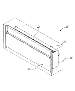
generally
provided with louvers. Although the existing electronic cabinets were
satisfactory to a
certain degree, there remains room for improvement, particularly when the
electronic
cabinet is used outdoors.
SUMMARY
[0004] It was found that although such louvers were satisfactory to prevent
natural
precipitations of water and snow to enter inside the housing of the cabinet,
such
louvers were generally unsatisfactory to prevent unnatural precipitations from
entering
inside the housing. For instance, when an electronic cabinet is located near a
road,
passage of vehicles (cars, trucks and snow plow trucks) on the road can cause
unnatural precipitations such as accidental and violent projections of water,
snow,
Date Recue/Date Received 2022-07-19
- 2 -
slush and/or particles towards the electronic cabinet. One need thus occurred
for
protecting the electronic cabinet from such unnatural precipitations while
still allowing it
to be satisfactorily ventilated. There is thus provided an electronic cabinet
which can be
weather resistant.
[0005] In accordance with one aspect, there is provided an electronic
cabinet for
enclosing electronic components, the electronic cabinet comprising: a housing
having a
base and a cover being connected to one another a plurality of lateral walls,
one of the
plurality of lateral walls having a first opening; a lateral perforated plate
being mounted
to the housing and extending over the first opening, the lateral perforated
plate having
a plurality of perforations; and a protector plate being mounted to the
housing and
extending over the lateral perforated plate to cover the plurality of
perforations of the
lateral perforated plate, the protector plate defining at least one air inlet
between the
protector plate and the lateral perforated plate.
[0006] In accordance with another aspect, there is provided an air inlet
module for
an electronic cabinet having an air inlet module opening, the air inlet module
comprising: a lateral perforated plate being mountable to the housing at the
air inlet
module opening and being sized and shaped to cover the air inlet module
opening, the
lateral perforated plate having a plurality of perforations; and a protector
plate being
outwardly mountable to the housing and being sized and shaped to extend over
the
lateral perforated plate to cover the plurality of perforations of the lateral
perforated
plate, the protector plate defining at least one air inlet between the
protector plate and
the lateral perforated plate when the protector plate and the lateral
perforated plate are
mounted to the housing of the electronic cabinet.
[0007] Many further features and combinations thereof concerning the present
improvements will appear to those skilled in the art following a reading of
the instant
disclosure.
DESCRIPTION OF THE FIGURES
[0008] In the figures,
Date Recue/Date Received 2022-07-19
- 3 -
[0009] Fig. 1 is a rear elevation view of an example of an electronic
cabinet including
a ventilation system having an air inlet module and an air outlet module;
[0010] Figs. 2A to 2F represent different views of the air inlet module of
Fig. 1;
[0011] Figs. 3A to 3F represent different views of the air outlet module of
Fig. 1;
[0012] Fig. 4 is an oblique view of an example of an air inlet module
having a
protector plate and a filter element;
[0013] Fig. 5 is an exploded view of the air inlet module of Fig. 4;
[0014] Figs. 6A to 6E represent different views of another example of an
air inlet
module having a protector plate and a filter element;
[0015] Fig. 7 is an enlarged view of a side elevation view of the air inlet
module of
Figs. 6A to 6E;
[0016] Figs. 8A to 8C are oblique views of the air inlet module of Figs. 6A
to 6E;
[0017] Fig. 9 is an oblique view of the air inlet module of Figs. 6A to 6E
mounted to a
housing of an electronic cabinet taken from the interior of the electronic
cabinet;
[0018] Fig. 10 is an oblique view of the air inlet module of Figs. 6A to 6E
mounted to
a housing of an electronic cabinet taken from the exterior of the electronic
cabinet;
[0019] Fig. 11 is an oblique view, taken from the bottom, of an example of
an
electronic cabinet having an air outlet module in accordance with another
embodiment;
[0020] Fig. 12 is a sectional and oblique view, taken from above, of the
electronic
cabinet of Fig. 11; and
[0021] Figs. 13A to 13F represent different views of the air outlet module
of Fig. 11.
Date Recue/Date Received 2022-07-19
- 4 -
DETAILED DESCRIPTION
[0022] Fig. 1 shows an example of an electronic cabinet 10, in accordance with
an
embodiment. The electronic cabinet 10 has a housing 12 generally having a base
14,
lateral walls 16 (including a back wall 18 and a front door 20 with a door
handle)
connected to the base 14 and a cover 22 connected to the lateral walls 16.
[0023] As depicted, the housing 12 encloses electronic components 24 inside
the
housing 12. The electronic components 24 can convert electrical energy into
thermal
energy which generally heats the air inside the housing 12 during use. To
evacuate the
heated air outside the housing 12, and thus prevent failures of some of the
electronic
components 24, the electronic cabinet 10 has a ventilation system 26 having an
air
inlet module 28 and an air outlet module 30.
[0024] To take advantage of natural convection, the air inlet module 28 is
generally
provided in a bottom portion 32 of the housing 12 whereas the air outlet
module 30 is
generally provided in a top portion 34 of the housing 12. Therefore, the
heated air,
which tends to go up due to its lower density (compared with unheated air), is
evacuated via the air outlet module 30 provided at the top portion 34 while
unheated/cooler air can enter inside the housing 12 via the air inlet module
28 provided
at the bottom 32 of the housing 12 and thus cools the interior of the housing
12. As it
will be understood by the skilled reader, the air inlet and outlet modules 28
and 30 are
not limited to the bottom and top portions 32 and 34 shown in Fig. 1. Any
other suitably
location can be used.
[0025] In this embodiment, the air inlet and outlet modules 28 and 30 are
removably
mounted to the housing 12 in order to be replaced when worn and/or broken, for
instance. More specifically, in this example, the door 20 (or any lateral
wall) has an air
inlet module opening 36 which receives the air inlet module 28 and the back
wall 18 (or
any lateral wall) has an air outlet module opening 38 which receives the air
outlet
module 30. In this example, the air inlet and outlet modules 28 and 30 are
mounted to
the housing 12 via fasteners (bolt and nuts, screws, weld lines, adhesive,
etc). These
Date Recue/Date Received 2022-07-19
- 5 -
fasteners are provided inside the housing 12 to be inaccessible from the
exterior of the
housing 12.
[0026] Figs. 2A to 2F show different views of the air inlet module 28. These
views
include a front elevation view A, a top elevation view B, a bottom elevation
view C, a
side elevation view D, an oblique view taken from below E and an oblique view
taken
from above F. As it can be seen, the air inlet module 28 has a frame 40 which
can be
received in the air inlet module opening 36 of the housing 12 of the
electronic cabinet
(see Fig. 1). The frame 40 has a lateral plate which is perforated with a
plurality of
perforations 41 (referred to as the "lateral perforated plate 42") and a top
plate which is
perforated with a plurality of perforations 43 (referred to as the "top
perforated plate
44"). The lateral perforated plate is sized and shaped to cover the air inlet
module
opening and extend over the air inlet module opening from the interior or from
the
exterior.
[0027] The perforations 41, 43 are sized and shaped to prevent objects or
animals to
enter inside the housing of the electronic cabinet while still allowing air to
enter therein.
It is noted that once the air has entered via the lateral perforated plate 42,
it can access
the interior of the housing of the electronic cabinet via the top perforated
plate 44. In
this example, the perforations 41,43 of the plates 42,44 are provided in a
rectangular
array of through holes. Other suitable perforations can be used.
[0028] Figs. 3A to 3F shows different views of air outlet module 30. These
views
include a front elevation view A, a top elevation view B, a bottom elevation
view C, a
side elevation view D, an oblique taken from below E and an oblique view taken
above
F. As it can be seen, the air outlet module 30 has an enclosure 46 which can
be
received in the air outlet module opening 38 of the housing 12 of the
electronic cabinet
10 (see Fig. 1). When received therein, the enclosure 46 has a lateral plate
which is
perforated with a plurality of perforations 45 (referred to as "the lateral
perforated plate
48") and a bottom air inlet 51 which is configured to face towards the
interior of the
housing of the electronic cabinet when mounted thereto.
Date Recue/Date Received 2022-07-19
- 6 -
[0029] There again, the perforations 45 are sized and shaped to prevent
objects or
small animals from entering inside the housing of the electronic cabinet while
still
allowing air flow through. Still in this example, the perforations 45 are
provided in a
rectangular array of through holes.
[0030] Fig. 4 shows another example of an air inlet module 28, in accordance
with
another embodiment. Broadly described, the air inlet module 28 has a frame 40
which
is receivable in the air inlet module opening 36 of the housing 12 of the
electronic
cabinet 10 (see Fig. 1) and mountable thereto via, for instance, bore holes
and
fasteners. The air inlet module 28 has a lateral perforated plate 42 mounted
to the
frame 40, a protector plate 50 mounted to lateral perforated plate 42 (or
directly
mounted to the frame 40) and a filter element 52 mounted to the frame 40. The
protector plate 50 is sized and shaped to extend over the lateral perforated
plate to
cover the plurality of perforations of the lateral perforated plate. The
filter element 52
extends over the air inlet module opening 36 to filter air and/or to prevent
precipitations
from entering inside the housing of the electronic cabinet.
[0031] Fig. 5 shows an exploded view of the air inlet module 28 showing the
frame
40, the lateral perforated plate 42, the protector plate 50 and the filter
element 52.
[0032] For instance, the frame 40 has a base 54, a back wall 56 being
connected to
the base 54 and extending upwardly therefrom, and two walls 58 connected at
least to
the base 54 and extending upwardly therefrom. The two walls 58 extend upwardly
farther than the back wall 56 does in this embodiment. As shown, the base 54
has a
forward horizontal edge 60 having a bottom flange 62 extending downwardly and
outwardly from the forward horizontal edge 60. The two walls 58 each have a
forward
vertical edge 64 having a side flange 66 extending laterally and outwardly
from a
respective one of the two forward vertical edges 64. The flanges 62 and 66
each have
one or more bore hole 68 used to mount the frame 40 of the air inlet module 28
to the
housing 12 of the electronic cabinet 10 using fasteners (not shown).
[0033] In this example, the lateral perforated plate 42 is mounted to the
frame 40 of
the air inlet module 28. For instance, the lateral perforated plate 42 has a
bottom edge
Date Recue/Date Received 2022-07-19
- 7 -
70 having one or more bore hole 68 which is fastenable to the one or more bore
hole
68 of the bottom flange 62 of the frame 40 of the air inlet module 28. During
use, these
bore holes 68 can be fastened to one another using one or more fastener. As it
can be
seen, the lateral perforated plate 42 has two lateral edges 72 each having a
side flange
74 extending outwardly from a respective one of the two lateral edges 72 of
the lateral
perforated plate 40. Each of these side flanges 74 have one or more bore hole
76.
[0034] In this embodiment, the protector plate 50 is mounted to the lateral
perforated
plate 42. For instance, the protector plate 50 has a top edge 78 having a top
flange 80
extending inwardly from the top edge 78 and two lateral edges 82 each having a
side
flange 84 extending inwardly from a respective one of the two lateral edges 82
of the
protector plate 50. It can also have a bottom edge 86 having a bottom flange
(not
shown in Fig. 5) extending inwardly from the bottom edge 86. Each of the side
flanges
84 of the protector plate 50 have one or more bore hole 76 used to mount the
protector
plate 50 to the lateral perforated plate 42 using fasteners. It is understood
that the top
flange 80 and the bottom flange of the protector plate 50 are sized and shape
to allow
air to pass between the protector plate 50 and the lateral perforated plate 42
when
mounted to one another.
[0035] As shown, the filter element 52 can be received onto the base 54 of the
frame
40 of the air inlet module 28 so as to filter the air that is to enter inside
the housing of
the electronic cabinet. The filter element 52 shown in this embodiment is
formed with
chicane members so as to prevent harsher or mechanically induced
precipitations from
damaging the electronic components of the electronic cabinet.
[0036] The chicane members of the filter element may include a back wall
connected to the base of the filter element and extending upwardly therefrom,
a first
wall connected to the back wall and extending forwardly and downwardly from a
top
edge of the back wall, a second wall connected the first wall and extending
downwardly
and inwardly from a forward edge of the first wall, a third wall connected to
the second
wall and extending upwardly and inwardly from an inward edge of the second
wall, at
least the first and third walls each having a plurality of perforations. For
instance, in this
embodiment, the filter element 52 has a base 88 to be received on the base 54
of the
Date Recue/Date Received 2022-07-19
- 8 -
frame 40, a back wall 90 connected to the base 88 and extending upwardly from
the
base 88, a first wall 92 connected to the back wall 90 and extending forwardly
and
downwardly from a top edge 94 of the back wall 90, a second wall 96 connected
the
first wall 92 and extending downwardly and inwardly from a forward edge 98 of
the first
wall 92, a third wall 100 connected to the second wall 96 and extending
upwardly and
inwardly from an inward edge 102 of the second wall 96. As shown, the first
and third
walls 92 and 100 are perforated with corresponding rectangular arrays of
perforations
103,104 for instance. This embodiment of the filter element 52 is not
limitative as it can
have any other suitable configuration.
[0037] Figs. 6A to 6E shows different views of another example of the air
inlet
module 28. These views include a front elevation view A, a top elevation view
B, a
bottom elevation view C (not to scale relative to the other views), a side
elevation view
D and a sectional view E taken along lines A-A. As it can be seen, in this
embodiment,
the air inlet module 28 can be received in the air inlet module opening 36 of
the
housing 12 of the electronic cabinet 10 (see Fig. 1). In this embodiment, the
air inlet
module 28 has a lateral perforated plate 42 directly mountable to the housing
of the
electronic cabinet, a protector plate 50 outwardly mounted to the lateral
perforated
plate 42, a filter element 52 inwardly mountable to the housing of the
electronic cabinet
and over the air inlet module opening 36 (see Fig. 1).
[0038] As best seen in the side elevation view D of the air inlet module 28,
the
protector plate 50 has a bottom edge 86 having a bottom flange 106 extending
inwardly from the bottom edge 86 and a top edge 78 having a top flange 80
extending
inwardly from the top edge 78. However, the bottom and top flanges 106, 80 do
not
reach the lateral perforated plate 42 such that they define a respective one
of a bottom
air inlet 108 and a top air inlet 110. A spacing between an edge of the bottom
flange
106 and the lateral perforated plate 42 defining the bottom air inlet 108 and
a spacing
between an edge of the top flange 80 and the lateral perforated plate 42
defining the
top air inlet 110.
[0039] Fig. 7 shows an enlarged view of the side elevation view E of the air
inlet
module 28 of Figs. 6A to 6E but mounted to the housing 12 of the electronic
cabinet.
Date Recue/Date Received 2022-07-19
- 9 -
As illustrated, air can follow an air path 112 which passes through the bottom
air inlet
108, then through the perforations 41 of the lateral perforated plate 42 and
then
through the filter element 52 prior to entering inside the housing of the
electronic
cabinet. As shown, the protector plate 50 can shield the perforations from
horizontally-
oriented projections of ice or water 114.
[0040] Figs. 8A to 8C show oblique views of the air inlet module 28 of Figs.
6A to
6E. The top air inlet 110 is best seen in inset E whereas both insets E and F
show that
the side flanges 84 of the protector plate 50 extend over the side flanges 74
of the
lateral perforated plate 42 in order to potentially prevent water, snow, slush
and/or
particles from entering inside the air inlet module 28.
[0041] Fig. 9 shows an oblique view of the air inlet module 28 of Figs. 6A to
6E
taken from the inside of the housing 12 of the electronic cabinet. The air
inlet module
opening 36 is outwardly covered by the lateral perforated plate 42 and its
array of
perforations 41 can be seen. In this view, there are provided filter element
receiving
guides 116 for receiving the filter element 42. In this embodiment, the filter
element
receiving guides 116 includes two vertical guides (only the guide 116a is
shown)
inwardly mounted along two side edges 118 of the air inlet module opening 36
of the
housing 12 of the electronic cabinet and one horizontal guide 116b inwardly
mounted
along a bottom edge 120 of the air inlet module opening 36 of the housing 12
of the
electronic cabinet. In this configuration, the filter element 52 is slidably
engageable to
the housing 12 of the electronic cabinet via the filter element receiving
guides 116. In
another embodiment, the filter element can be fastened to the housing of the
electronic
cabinet or alternately be snapingly engaged thereto depending on the
application.
[0042] Fig.
10 shows an oblique view of the air inlet module 28 of Figs. 6A to 6E
taken from the outside of the housing 12 of the electronic cabinet. The
lateral
perforated plate 42 is mounted to the housing 12 of the electronic cabinet via
bore
hole(s) and fastener(s) 122. The side flanges 84 of the protector plate 50 are
fastened
to the side flanges 74 of the lateral perforated plate 42 via bore holes and
fasteners
124. The top air inlet 110 is well seen in this view.
Date Recue/Date Received 2022-07-19
- 10 -
[0043] Fig. 11 shows an oblique view, taken from the outside and from below,
of
another example of an electronic cabinet 10 having another example of an air
outlet
module 30. As shown, the electronic cabinet 10 has a housing 12 having lateral
walls
16 including a door 20 hinged to one of the lateral walls 16 and a cover 22
connected
to the lateral walls 16. As shown, the air outlet module 30 is provided
proximate to the
cover 22 of the housing 12 of the electronic cabinet 10 in this example.
[0044] As shown, the door 20 is recessed relative to the cover 22 of the
housing 12
thus defining a spacing 130 between the door 20 and the cover 22. The recessed
portion of the cover 22 has a bottom perforated plate 132 facing downwardly to
evacuate the heated air from inside the housing 12 of the electronic cabinet
10 during
use.
[0045] Fig. 12 is an oblique and sectional view of a top portion of the
electronic
cabinet 10 shown in Fig. 11. One can see the cover 22 of the housing 12 and a
section
of the air outlet module 30. In this example, the air outlet module 30 has an
enclosure
46 mountable to the interior of the electronic cabinet 10. The enclosure 46
has the
bottom perforated plate 132 wherein the perforations are provided at a first
end 132a
and a bottom air inlet 134 provided in the form of a hole at second end 132b,
opposite
the first end 132a, of the bottom perforated plate 132. In this embodiment,
the
enclosure 46 has two chicane members 136 mounted inside the enclosure 46 to
create
the air path 138. The enclosure 46 can have one or more than two chicane
members.
[0046] Figs. 13A to 13F shows different views of the air outlet module 30
of Fig. 11.
These views include a front elevation view A, a top elevation view B, a bottom
elevation view C, two oblique views D and E and a side elevation view F (not
to scale)
taken along lines C-C. In this example, the air outlet module 30 has an air
blower 140
mounted inside the enclosure 46 and over the bottom air inlet 134 to blow air
from the
interior of the housing of the electronic cabinet to the outside thereof via
the bottom
perforated plate 132 along the air path 138.
Date Recue/Date Received 2022-07-19
-11 -
[0047] As can be understood, the examples described above and illustrated are
intended to be exemplary only. The filter element of the air inlet module is
optional. The
scope is indicated by the appended claims.
Date Recue/Date Received 2022-07-19