Note: Descriptions are shown in the official language in which they were submitted.
CA 02924525 2016-03-16
WO 2015/049097 1
PCT/EP2014/069362
CONNECTING ELEMENT FOR A TUBULAR COMPONENT OVERLAID WITH A METALLIC COMPOSITE
DEPOSIT AND
METHOD OF OBTAINING SUCH ELEMENT
The present invention relates to a connecting element for a tubular component,
said
connecting element being overlaid with a particular metallic composite
coating.
The term "tubular component" as used in the present invention means any
element or
accessory used to drill or operate a well.
The term "connecting element" as used in the context of the present invention
means any
end element of a tubular component which participates in connecting the
tubular component with
another tubular component.
A tubular component is intended to be connected, via one or more connecting
elements,
in particular a threading, a sealing surface and an abutment shoulder, to
another tubular
component in order to constitute a threaded tubular connection with that other
tubular component.
The tubular component may, for example, be a relatively great-length tube (in
particular
approximately ten metres in length), a tubular coupling a few tens of
centimetres in length, an
accessory for such tubes (a suspension device or hanger, a part for adapting
cross-sections, or
cross-over, a safety valve, a drill pipe connector or tool joint, a sub, and
the like).
The tubular components are generally connected one with another for dropping
into the
hydrocarbon well or similar well and to constitute a drill stem, a casing
string or a liner or tubing
string, or indeed an operating string.
API specification 5CT issued by the American Petroleum Institute (API),
equivalent to
ISO standard 11960 : 2004 issued by the International Standardisation
Organisation (ISO)
governs the specifications for tubes used as casing or tubing, and API
specification 5B defines
standard threadings for such tubes. API specification 7 defines threaded
connectors with a
shoulder for rotary drill pipes.
The manufacturers of tubular components with threaded connections have also
developed
threaded connections known as premium connections which have threadings with
specific
CA 02924525 2016-03-16
WO 2015/049097 2
PCT/EP2014/069362
geometries and specific means for providing better performance in service, in
particular in the
matter of mechanical strength and sealing. Examples of such premium threaded
connections and
those specific means are described, for example, in patent documents EP 1 631
762, US 7 334 821,
US 7 997 627, US 7 823 931, US-2010/301603, US-2011/0025051, US 7 900 975, US
8 038 179,
US-2011/241340, EP 0 488 912, EP 0 767 335, EP 1 269 060 and US 4 494 777, EP
2501 974 and
WO-2012/025461.
These threaded ends, as well as the bearing surfaces and abutment shoulders,
are machined
very precisely in order to comply with the profiles and geometries required to
reach the requisite
performances.
Thus, it is vital that these ends, which have been very finely and carefully
machined, are
damaged, polluted and deteriorate as little as possible between the time they
leave their production
line and the time they are put into use, but also between two successive uses.
It will be understood
that it is in fact necessary to protect not only the threading, but also any
bearing surface(s) and
abutment shoulder(s) which each have functions which are specific and
complementary to those of
the threadings and which together provide an effective seal when in use
against shocks (knocks),
corrosion and dust.
The first desired quality for the connecting elements is hardness.
In particular, the abutment shoulders are exposed to knocks and impacts
generated during
handling of tubular components in particular when being stored on the drilling
platform (rig) or on a
base or during the operation when the male portion and the female portion, in
particular the
threadings, of the tubular components are brought into contact before makeup
(stabbing operation).
In addition, the abutment shoulders have to be capable of tolerating
mechanical loads in
terms of compression, tension and torsion during operation.
Thus, hardness is an essential property for abutment shoulders.
CA 02924525 2016-03-16
WO 2015/049097 3
PCT/EP2014/069362
The threadings must also have good properties in terms of hardness. In fact,
the threadings
must have good galling protection properties. Increasing the surface hardness
allows to protect the
threading from galling.
In addition, increasing the hardness allows to prevent the transfer of
material from one
surface to another.
Finally, the threadings must not wear during makeup and breakout operations.
The sealing surfaces must also have sufficient hardness, in particular because
the sealing
surfaces are responsible for the seal of the connection for the tubular
components. In fact, a sealing
surface is a surface which is generally tapered in shape, located on the end
of a first tubular
component which, when two tubular components are connected together via their
respective ends, is
caused to exert a pressure on the sealing surface of the end of a second
component. These two
tapered surfaces in contact and under pressure can be used to create a seal
and prevent the passage
of fluids between a zone termed an internal zone of the connected tubular
components and a zone
which is external of the connected tubular components. These components may be
used when
connected to participate in extracting oil from a well, and inside these
wells, and thus inside the
components, there may be a column of liquid under very high pressure.
The connecting elements must also perform well in terms of corrosion
resistance and
lubricating properties.
In particular, the elements of the connection can be stored for several years
before being
used, sometimes in highly aggressive environments.
Lubricating properties are particularly important for the threadings. The
abutment shoulders
also have to be lubricated, but to a lesser extent than the threadings.
The threadings should also be protected against galling, in particular during
makeup and
breakout operations. In fact, at the well, the threadings have to be able to
undergo several makeup
and breakout cycles. Makeup operations are carried out vertically under a high
axial load, for
example the weight of a tube several metres in length (typically 10 to 13
metres) to be connected
CA 02924525 2016-03-16
WO 2015/049097 4
PCT/EP2014/069362
vertically via the threaded connection, which gives rise to galling risks, in
particular in the
threadings. This load may also be localized due to a slight misalignment in
the axes of the threaded
elements to be connected because the tube to be connected is suspended
vertically, increasing the
risks of galling.
The connecting elements for the tubular components cited above are generally
coated with
an anti-corrosion grease which is removed just before they are connected.
Before such connection,
the anti-corrosion grease is removed and a lubricating grease is added (the
operation is known as rig
preparation). However, prior art greases suffer from a certain number of
disadvantages linked to
their amount of toxic constituents, to the pollution they generate and to the
number of prior steps
necessary before being able to drop a component into the well. In particular,
cleaning of the anti-
corrosion grease (also known as storage grease) is traditionally carried out
with a high pressure
water jet. The operation is lengthy, dirty, might contaminate other
connections in the vicinity and
necessitates using holding and re-processing tanks for the effluents in order
to comply with
environmental standards.
Patent documents US 6 027 145, EP 1 211 451 and EP 1 934 508 disclose that it
is known to
apply a dry lubricant comprising solid lubricant particles at the factory. In
these cases when a dry
lubricant is used at the factory, it is then necessary to protect the layer of
lubricating product with
which the ends of the components is coated as much as possible, both from
mechanical removal and
from pollution (sand, debris) which could have a detrimental effect on the
efficacy of the lubricating
product.
To this end, it is also known that these layers of product, which are applied
at the factory as
soon as the threaded end has been manufactured, are aimed at providing both
anti-corrosion
protection of the end during the storage period and lubrication for subsequent
makeup of that end,
as taught in particular in documents WO 2004/033951 or WO 2008/125740. In
particular,
lubrication must be able to control the characteristic curve of the makeup
torque of the connection
in order to guarantee the final seal.
CA 02924525 2016-03-16
WO 2015/049097 5
PCT/EP2014/069362
The compositions used may be composed of a multi-functional coating which is
both
anticorrosive and lubricating, as described in WO 2008/125740 applied to each
end to be connected,
or to superimposed layers as described in WO 2004/033951, where some are
lubricants and others
protect against corrosion.
Whatever they are, during makeup, the anti-corrosion elements are mixed with
the
lubricating elements and will modify the lubricating behaviour which would be
observed without
them. It has frequently been demonstrated that coupling between these
functions is very strong and
contradictory. An improvement in the anti-corrosion behaviour of a design
generally results in
deterioration in the lubricating power and vice versa, an improvement in the
lubricating power
reduces the corrosion behaviour during storage. The performance of the
compromises proposed by
the prior art solutions is limited.
Further, the dry anti-corrosion coatings normally used cannot guarantee very
long periods of
corrosion resistance, in particular in highly aggressive environments (marine
environment,
industrial environment, high precipitation environment and/or large
temperature ranges, for
example).
Thus, there is a need for the provision of connecting elements which have good
properties in
terms of hardness, corrosion resistance and lubrication which do not suffer
from the disadvantages
of the prior art.
Thus, the invention provides a connecting element for a tubular component,
said connecting
element being overlaid with a coating comprising a principal layer constituted
by a nickel-
phosphorus alloy.
The phosphorus generally represents 5% to 13%, preferably 8% to 13%, more
preferably
10% to 12%, even more preferably 10.5% to 11.5% by weight of the total weight
of the nickel-
phosphorus alloy.
CA 02924525 2016-03-16
WO 2015/049097 6
PCT/EP2014/069362
In accordance with a first embodiment of the invention, the thickness of the
principal layer
constituted by the nickel-phosphorus alloy is advantageously in the range 5 to
10 gm. Said
thickness allows to provide the hardness required for the connecting element.
In accordance with a second embodiment of the invention, the thickness of the
principal
layer constituted by the nickel-phosphorus alloy is advantageously 15 to 35
gm, preferably 20 to 35
gm, more preferably 25 to 30 gm. Such a thickness not only allows to provide
the hardness
required for the connecting element, but also allows to provide protection
against corrosion.
Such a nickel-phosphorus alloy layer has been proposed by the company
MACDERMID
under the trade name NIKLAD XD7647.
In accordance with a preferred embodiment, the coating further comprises an
additional
layer constituted by a nickel-phosphorus alloy comprising the particles of one
or more solid
lubricant compounds, said additional layer being disposed on said principal
layer.
A solid lubricant is a solid and stable substance which is interposed between
two friction
surfaces in order to reduce the coefficient of friction and to reduce wear and
damage to the surfaces.
These substances can be classified into various categories defined by their
functional
mechanism and their structure. These categories are described, for example, in
the hand-outs
entitled "Les lubrifiants solides [Solid lubricants]" issued by Mr Eric Gard
at the Ecole Nationale
Superieure des Paroles et Moteurs (France):
= class 1: solid substances owing their lubricating properties to their
crystalline structure,
for example graphite, boron nitride BN or zinc oxide Zn0;
= class 2: solid substances owing their lubricating properties on the one
hand to their
crystalline structure and on the other hand to a reactive chemical element in
their
composition, for example molybdenum disulphide Mo52, graphite fluoride, tin
sulphides
or bismuth sulphides;
CA 02924525 2016-03-16
WO 2015/049097 7
PCT/EP2014/069362
= class 3: solid substances owing their lubricating properties to their
chemical reactivity,
for example certain chemical compounds of the thiosulphate type (for example
Desilube
88 marketed by Desilube Technology Inc.);
= class 4: solid substances owing their lubricating properties to a plastic
or viscoplastic
behaviour under frictional load, for example polytetrafluoroethylene (PTFE) or
polyamides.
Silicon carbide and tungsten carbide may also be cited.
The particles of one or more solid lubricant compounds are advantageously
selected from
particles of polytetrafluoroethylene, talc, mica, boron nitride, silicon
carbide, tungsten carbide,
tungsten sulphide, molybdenum sulphide and mixtures thereof
Preferably, the particles of one or more solid lubricant compounds are
selected from
polytetrafluoroethylene particles.
Advantageously, the phosphorus of the nickel-phosphorus alloy comprising the
particles of
one or more solid lubricant compounds represents 5% to 13%, preferably 8% to
13%, more
preferably 10% to 12% by weight of the total weight of the nickel-phosphorus
alloy comprising the
particles of one or more solid lubricant compounds.
The particles of one or more solid lubricant compounds advantageously
represent 20% to
35% by volume, preferably 25% to 30% by volume with respect to the total
volume of the nickel-
phosphorus alloy comprising the particles of one or more solid lubricant
compounds.
The thickness of said additional layer constituted by a nickel-phosphorus
alloy comprising
the particles of one or more solid lubricant compounds may be in the range 3
to 13 gm, preferably 5
to 10 gm.
A layer of nickel-phosphorus alloy of this type comprising
polytetrafluoroethylene particles
has been proposed by the company MACDERMID under the trade name NIKLAD ICE
Ultra.
CA 02924525 2016-03-16
WO 2015/049097 8 PCT/EP2014/069362
Furthermore, the coating may comprise a lubricant layer disposed on said
principal layer or
on said additional layer when the coating comprises said additional layer.
The lubricant layer may be selected from a grease, a semi-solid lubricant
layer or a solid, dry
lubricant layer comprising one or more solid lubricant particles in a resin.
The semi-solid lubricant layer generally comprises one or more extreme
pressure additives,
one or more solid lubricant particles, one or more metallic soaps and one or
more low melting point
waxes. Such semi-solid lubricant layers are described, for example, in patent
application
FR 2 937 046.
The solid, dry lubricant layer generally comprises one or more solid lubricant
particles for
reducing friction in a resin binder such as an organic or inorganic polymer,
selected from heat
curable epoxy, polyurethane, unsaturated polyester, polyphenylsulphone,
polyimide and silicone
resins; thermoplastic polyolefin, olefin copolymer, polyamide, polyamide-
imide,
polyaryletherketone resins; alkaline polysilicates with a 5i02/Mx0 ratio of
more than 2, where
M=Na, K or Li; organometallics such as alkoxy-titanates or ethyl silicate.
In accordance with a first embodiment, the connecting element of the invention
may be a
threading.
In accordance with a second embodiment, the connecting element of the
invention may be a
sealing surface.
In accordance with a third embodiment, the connecting element of the invention
may be an
abutment shoulder.
The invention also concerns a tubular component comprising one or more
connecting
elements in accordance with the invention.
More particularly, the tubular component of the invention is produced from
steel, in
particular steels such as those described in API 5CT standards, for example
those comprising
carbon in a proportion of less than 0.25%, and/or preferably, steels with a
grade such as those
defined in the standards IS011960 and IS013680 and/or a H40, J55, 1(55, M65,
L80, C90, C95,
CA 02924525 2016-03-16
WO 2015/049097 9
PCT/EP2014/069362
T95, P110, Q125, carbon steel or a 13Cr or Sl3Cr or Duplex 22Cr + 25Cr or
Super-Duplex 25Cr
martensitic steel, or a Fe 27Cr austenitic steel.
In accordance with a first embodiment, the tubular component of the invention
comprises a
threading which is a connecting element in accordance with the invention. In
this embodiment, the
tubular component of the invention may also comprise an abutment shoulder
which is a connecting
element in accordance with the invention.
In a second embodiment, the tubular component of the invention comprises an
abutment
shoulder which is a connecting element in accordance with the invention.
In a third embodiment, the tubular component in accordance with the invention
comprises a
sealing surface which is a connecting element in accordance with the
invention. In this
embodiment, the tubular component in accordance with the invention may also
comprise a
threading which is a connecting element in accordance with the invention
and/or an abutment
shoulder which is a connecting element in accordance with the invention.
A tubular component of the invention may be connected via one or more
connecting
elements, which may or may not be in accordance with the invention, in
particular a threading, a
sealing surface and an abutment shoulder, to another tubular component which
may or may not be
in accordance with the invention, to form a threaded tubular connection.
In particular, at one of its ends, the tubular component has a threading
formed on its outer or
inner peripheral surface depending on whether the threaded end is male or
female in type, this
threading allowing the component to be connected to a complementary component.
A female tubular component of the invention comprising one or more connecting
elements
overlaid with a coating constituted by the principal layer and the optional
additional layer as defined
above may be connected with a male tubular component which is not in
accordance with the
invention and which comprises one or more connecting elements overlaid only
with a lubricant
layer as defined above.
CA 02924525 2016-03-16
WO 2015/049097 10
PCT/EP2014/069362
A female tubular component in accordance with the invention comprising one or
more
connecting elements overlaid with a coating constituted by the principal
layer, the optional
additional layer and the lubricant layer as defined above may be connected
with a male tubular
component in accordance with the invention and which comprises one or more
connecting elements
overlaid with a principal layer and an optional additional layer as defined
above.
A female tubular component in accordance with the invention comprising one or
more
connecting elements overlaid with a coating constituted by the principal
layer, the optional
additional layer and the lubricant layer as defined above may be connected
with a male tubular
component in accordance with the invention and which comprises one or more
connecting elements
overlaid with a principal layer, an optional additional layer and a lubricant
layer as defined above.
Using the connecting elements in accordance with the invention and tubular
components in
accordance with the invention means that the steps for cleaning and
lubrication of the connections
before use can be dispensed with (rig ready solution). The coating used in
accordance with the
invention is highly adhesive and not deformable, and so avoids using specific
protectors specially
designed to limit damage to the coatings (for example contactless protectors
on the threads or a
sealed protector).
Protectors are in fact devices which are becoming more and more complicated in
order to
protect the threads and the connection against corrosion and damage to the
coatings. The present
invention means that simplified protectors can be used, for example non-
sealing protectors or even
protectors the manufacturing specifications for which no longer need to be too
severe in order to
ensure that the contact between the surfaces of the protector and the surfaces
of the connection is
very good.
The coating used in accordance with the invention has a good level of
corrosion resistance
by providing cathodic protection of the substrate. The optional presence of
particles of lubricant
compounds as defined above and which have a low wettability also mean that
corrosion resistance
is improved.
CA 02924525 2016-03-16
WO 2015/049097 11
PCT/EP2014/069362
Finally, the coating used in accordance with the invention does not wear
during successive
makeup operations. Thus, it can continue to guarantee the anti-corrosion
behaviour quality even
after several makeup/breakout cycles without necessitating supplemental anti-
corrosion protection.
In addition, its high wear resistance means that debris or dust which can be
observed upon breakout
is not generated.
The invention also concerns a method for producing a connecting element as
defined above,
in which the principal layer and optional additional layer are deposited by
autocatalytic deposition.
The principal layer constituted by a nickel-phosphorus alloy used in
accordance with the
invention may be deposited on the connecting element by autocatalytic
deposition. Autocatalytic
deposits of nickel-phosphorus alloy are described in NF standard EN ISO 4527,
as well as in the
document by Louis LACOURCELLE ¨ Nickelage chimique [Chemical nickeling],
Techniques de
l'Ingenieur, Metallic materials essay.
Autocatalytic deposits of nickel-phosphorus alloy are proposed by the company
MACDERMID under the trade name NiKladTmELV.
The additional layer optionally used in accordance with the invention,
constituted by a
nickel-phosphorus alloy comprising particles of one or more lubricant
compounds, may be obtained
by autocatalytic deposition.
Auto catalytic deposits of nickel-phosphorus alloy containing particles of
polytetrafluoroethylene have been proposed by the company MACDERMID under the
trade name
NiK1adTM ICE ULTRA.
Deposition of the principal layer used in accordance with the invention and of
the possible
additional layer used in accordance with the invention may be carried out
using an autocatalytic
method comprising the following steps:
= cleaning the surface of the connecting element; cleaning may be carried
out by alkaline
degreasing, then rinsing, then electrolytic degreasing, then rinsing, then
acid stripping, then
rinsing; then:
CA 02924525 2016-03-16
WO 2015/049097 12
PCT/EP2014/069362
= depositing the nickel-phosphorus, then depassivating the surface, then
optional deposition of
nickel-phosphorus supplemented with particles of lubricant compound, then
rinsing; then
= oven drying, for example at a temperature of the order of 70 C; then
= a degassing treatment in an oxidizing atmosphere, typically for 2h at 220
C.
In accordance with a first embodiment, this method may also include a
posterior heat
treatment at a temperature which is preferably in the range 250 C to 300 C,
for example for a
period of 3 to 5 h.
This posterior heat treatment allows to increase the hardness of the coating
and thus of the
threading, and to improve the anti-galling performances without, however,
deteriorating the
corrosion protection performances.
In accordance with a second embodiment, this method may also comprise a
posterior heat
treatment step carried out at a temperature which is preferably in the range
300 C to 600 C, for
example for a period of 3 to 5 h. In this case, the hardness of the coating is
substantially increased,
for example from 500 Hk when the method does not comprise this posterior heat
treatment step to
800 Hk when it comprises this step, but the corrosion protection performances
deteriorate.
Some features of the invention are disclosed in more detail in the following
description
made with reference to the accompanying drawings:
Figure 1 is a diagrammatic view of a connection resulting from connecting two
tubular
components by makeup.
Figure 2 is an enlarged view of the zone in box A of Figure 1.
Figure 3 is a detailed view of the cooperation between the threads of two
connected tubular
components.
Figure 4 is a detailed view of a connecting element (threading) of the
invention overlaid
with a coating.
The threaded connection shown in Figure 1 comprises a first tubular component
with an axis
of revolution 9 provided with a male end 1 and a second tubular component with
an axis of
CA 02924525 2016-03-16
WO 2015/049097 13
PCT/EP2014/069362
revolution 9 provided with a female end 2. The two ends 1 and 2 each end in a
terminal surface
orientated radially with respect to the axis 9 of the threaded connection and
are respectively
provided with threaded portions 3 and 4 which cooperate together for mutual
connection by makeup
of the two components. The threaded portions 3 and 4 may be of the trapezoidal
or other thread
type. In the example shown, the threaded portions have threads with a
vanishing profile at the
respective ends of the threaded portions. These vanishing profiles extend over
a portion of the axial
extent of the threaded portion. In particular, a portion of the threaded
portion with a vanishing
profile 10 does not cooperate with a complementary threading.
In addition, as can be seen in Figure 2, metal/metal sealing surfaces (bearing
surfaces) 5, 6
intended to come into an interference sealing contact one against the other
after connection of the
two threaded components by makeup are respectively provided on the male and
female ends close
to the threaded portions 3, 4. Finally, the male end 1 ends in a terminal
surface 7 which abuts
against a corresponding surface 8 provided on the female end 2 when the two
ends are made up one
into the other. The surfaces 7 and 8 are termed abutment shoulders.
Figure 3 shows a detail of a thread of a threaded portion. Each thread thus
comprises a load
flank 11 forming an angle 12 in the range -50 to +50 with respect to the
normal N to the connection
axis 10. The load flank is connected via a crest 13 to a stabbing flank 14. In
particular, the
connection shown is such that in the final position of the connection, the
load flanks of the male
threaded portion 3 are in contact with the corresponding load flanks of the
female threaded portion
4.
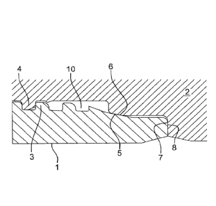
Figure 4 shows the male end 1 of a tubular component in which the threaded
portion 3 and
the sealing surface 5 (bearing surface) are overlaid with a coating 15 as
defined in the invention.
Example
A metallic coating of a principal layer of a nickel-phosphorus alloy
comprising 11% by
weight of phosphorus, and an additional layer of a nickel-phosphorus alloy
comprising
CA 02924525 2016-03-16
WO 2015/049097 14
PCT/EP2014/069362
polytetrafluoroethylene (PTFE) particles in an amount of 25% by volume with
respect to the
volume of the alloy, was produced on a L80 grade carbon steel threading.
The principal layer was deposited using the autocatalytic method proposed by
the company
MACDERMID with the trade name NiK1adTM ELV.
The additional layer was deposited using the autocatalytic method proposed by
the company
MACDERMID with the trade name NiK1adTM ICE ULTRA.
The principal nickel-phosphorus layer was 29 gm thick. The additional nickel-
phosphorus-
PTFE layer was 7.4 gm thick.
The metallic composite deposit obtained had a hardness of at least 550 Hk
under 10 g.
The metallic composite deposit had very good corrosion resistance.
Tests were carried out on the shore at a marine industrial exposure site (port
of Dunkirk)
classed as level 4 (high) on a scale of up to C5 (see "Corrosivity Class" in
accordance with ISO
standard 9223).
After 12 months exposure in Dunkirk with a protector, no signs of rust were
observed.
After 12 months exposure in Dunkirk without a protector, a few rare spots of
corrosion were
observed (Re 1 on the European scale for degree of rusting, ISO 4628-3).
After 24 months exposure in Dunkirk with a protector, no signs of rust were
observed.
The metallic composite deposit was not damaged during a scratch test type test
where it was
subjected to an increasing load from lON to 300N provided by a tungsten
carbide bead with a
diameter of 5 mm. In contrast to other metallic deposits (Cu-Sn-Zn alloy
type), the deposit does not
crack; no detachment or delamination of the coating was observed.
The metallic composite deposit had excellent anti-galling performances.
Laboratory tests (Vee block test with a constant 785N load, equivalent to a
contact pressure
of 500-600 MPa, characteristic of the contact pressures occurring during
makeup of a connection at
the threads) exhibited highly progressive wear during use of nickel-phosphorus
supplemented with
PTFE compared with a metallic deposit of a ternary Cu-Sn-Zn alloy.
CA 02924525 2016-03-16
WO 2015/049097 15
PCT/EP2014/069362
Makeup curves very similar to those obtained with an API grease were obtained:
highly
regular slopes (not bumpy), with clearly identifiable changes in the slope.
Corrosion tests according to ISO Standard 9227 ¨ Corrosion tests in artificial
atmospheres
or salt spray tests - have been carried out on a sample corresponding to the
example described
above (noted with sample reference "D") and was compared to samples with
various thicknesses of
constituting layers. All the samples are L80 grade carbon steel threaded
elements overlaid with a
principal layer of a nickel-phosphorus alloy comprising 11% by weight of
phosphorus, and an
optional additional layer of a nickel-phosphorus alloy comprising
polytetrafluoroethylene (PTFE)
particles in an amount of 25% by volume with respect to the volume of the
alloy.
All those samples have been exposed to neutral spray test (NSS) for at least
1000 hours,
Results are given according to ISO standard 9227, on a European scale with
levels of rust ranging
from Re0 to Re9; level Re0 corresponding to a 0% rusted surface; Re3
corresponding to a 1%
rusted surface; Re5 corresponding to a 8% rusted surface; Re6 corresponding to
a 40%-50% rusted
surface.
Sample Coating Rust level after Rust level after
reference 500h exposure 1000h exposure
(Re scale) (Re scale)
A One principal layer 4 . 5 6
NiP from 25ium to
3 1 lam
B One principal layer 3 4 . 5
NiP from 15ium to
lam and one
additional layer of
NiP-PTFE from 5ium
to 10ium
C One principal layer 2 . 6 4 . 5
NiP from 20ium to
lam and one
additional layer of
NiP-PTFE from 5ium
to 10ium
CA 02924525 2016-03-16
WO 2015/049097 16
PCT/EP2014/069362
D One principal layer 2.3 2 . 8
NiP from 25ium to
30 lam and one
additional layer of
NiP-PTFE from 5ium
to 10ium
The sample D with a coating comprising a principal layer of Nickel ¨Phosphorus
alloy having a
thickness in the range 25um to 30um and an additional layer of Nickel
Phosphorus comprising
particles of PTFE lubricant presents an excellent behaviour to corrosion.