Note: Descriptions are shown in the official language in which they were submitted.
POSITIVE DISPLACEMENT STOPPER FOR A PRE-FILLED SYRINGE
BACKGROUND OF THE INVENTION
Field of the Invention
[0001] The invention relates in general to a stopper assembly for use with a
syringe and,
more particularly, to a stopper assembly having a positive displacement
feature for use with a
pre-filled syringe such as those used in flush applications. The invention
also relates to a
plunger rod and an attachment member adapted for attachment with a stopper
assembly.
Description of Related Art
[0002] Pre-filled
syringes, such as those used in flush applications, are typically filled with
a saline solution and are used to flush catheters. Example pre-filled syringes
are shown in
United States Patent Nos. 6,361,524 and 6,743,216, which are directed to
syringe assemblies
for flush applications. At the end of the flushing procedure, the nurse or
technician bottoms
out the stopper in the syringe barrel. The process of bottoming the stopper in
the barrel can
cause a phenomenon known as reflux. Reflux is the reversal of fluid flow up
through the
catheter, usually due to the spring back of the stopper at the end of a flush
injection. This
occurs because the stopper compresses to force out additional saline, and
subsequently
springs back to shape. This causes the syringe to pull saline back into the
syringe. This
reflux can also pull blood back into the catheter, clogging it. This
phenomenon of reflux is
detrimental to the maintenance of the catheter line. Accordingly, it is
desirable to reduce or
eliminate reflux within the syringe.
[0003] Existing stopper designs typically include a constant diameter seal and
a constant
stopper-to-barrel interference to create a seal that will prevent fluid housed
inside the barrel
from leaking past the front seal of the stopper. The contact pressure of the
seal is determined
by the interference in these designs, and has to be sufficiently high enough
such that they will
not leak under the highest possible fluid pressure inside the barrel. The
disadvantage of this
traditional design is that the higher contact pressures lead to higher static
and dynamic
frictional forces. Static friction is commonly referred to as break loose
force. Additionally,
these existing stoppers typically include tip designs that are not self-
centering. Because the
tips are not self-centering, they do not form a positive seal with the inside
back of the luer
taper when subjected to axial forces.
[0004] Existing stopper designs have attempted to prevent the flow of fluid
from the
catheter back into the syringe when the clinician does not use a recommended
positive
pressure flushing technique, and release the force from the plunger rod prior
to clamping the
1
CA 2924634 2017-06-09
CA 02924634 2016-03-17
catheter. As discussed above, blood entering back into the distal catheter
lumen is known as
reflux and this reflux can lead to clogged catheters. These previous designs
focused on
preventing spring-back of the stopper that would create a vacuum to draw fluid
back into the
syringe. These designs, while effective in reducing reflux, do not
consistently prevent all
reflux from occurring.
[0005] Pre-filled
syringes are typically manufactured in an automated process. The
process of manufacturing these pre-filled syringes includes the steps of
molding the syringe
barrel, attaching the cap, filling the barrel, inserting the stopper,
sterilizing the filled syringe,
then inserting the plunger rod. Because the filled syringes are typically
sterilized in an
autoclave, size of the syringe is an issue. For this reason, the syringe is
typically sterilized
prior to the insertion of the plunger rod. Commonly used plunger rods are
those of a snap-fit
design, attached to the stopper prior to inserting the stopper into the
barrel, or a threaded
design, attached to the stopper after the stopper has been inserted into the
barrel. Plunger
rods assembled into the stopper after the stopper has been inserted into the
barrel require a
significant amount of force to be applied thereto during insertion. Axial
forces applied to the
plunger rod can cause the rod to become dislodged from the stopper, be
misaligned, and/or
break. Additionally, currently used snap-fit and/or threaded plunger rods
occasionally
become dislodged from the stopper during use.
[0006] Traditional plunger rods are typically cylindrical members, which are
formed from
a molded material. These known rods may have a ridged surface wherein four
ribs,
positioned 900 degrees with respect to one another, form the ridged surface.
In this current
four ribbed design, a user may apply a side load during flushing or aspiration
that may be
normal to the edge of the rib, causing minimal side loading deflection, or
normal to the region
between the ribs (450 from a rib), causing maximum side loading deflection.
Additionally,
the solid design of the stopper rod adds unnecessary material costs to the rod
and may
undesirably flex in an axial direction during use.
SUMMARY OF THE INVENTION
[0007] There is a need in the art for a stopper design that is self-centering
to insure a seal
with the syringe outlet to allow for pressure generation to create a positive
displacement.
There is a further need in the art for a stopper design that creates an active
seal via the
interaction of the stopper and plunger rod to transmit a radial force with
respect to the barrel.
The concept of an active seal involves an increase in pressure inside the
syringe barrel which
will cause the forward seal of the stopper to have a higher contact pressure
with the inside
2
CA 02924634 2016-03-17
walls of the barrel, maintaining a higher contact pressure than the internal
fluid pressure,
thereby preventing leakage at the stopper seal. There is yet another need in
the art for a
stopper -design that includes a feature that allows for the capture and
storage of potential
energy prior to the release of the force from the plunger rod, effectively and
consistently
reducing and/or eliminating reflux of fluid back into the syringe upon this
release of pressure
on the plunger rod. There is also a need in the art for a plunger rod
attachment design that
can be easily inserted into the stopper of a pre-filled, sterilized syringe
with the application of
minimal force thereto and which is securely held within the stopper during use
of the syringe.
There is a further need in the art for a plunger rod design that uses a
reduced amount of
processing material, has a reduced molding cycle time, and has a high
resistance to side
loading.
[0008] The particularly disclosed stopper designs create a positive
displacement of fluid
out of the syringe (and therefore into any attached catheter, for example)
after the stopper has
been bottomed in the syringe barrel and force is released from the plunger rod
so as to
effectively and consistently reduce and/or eliminate reflux of fluid back into
the syringe upon
the release of pressure on the plunger rod. The stopper is adapted for
attachment with a
plunger rod for use within a syringe barrel.
10009] According to one aspect of the invention, the stopper comprises a
main body
defining an open rearward end and closed front end. The open rearward end is
adapted to
receive a front forward end of the plunger rod. A core member is integrally
formed with the
main body adjacent the closed front end. The core member includes a nose
portion having a
profile adapted to create a positive seal with an interior surface of an
outlet opening of the
syringe barrel, such as through direct contact with an internal luer taper
surface. The core
member includes a front portion, a back portion, and a central portion
positioned between the
front and back portion wherein the front portion extends beyond the front end
of the main
body. The core member is interconnected with the main body via a flexible
membrane
extending between the core member and main body. At least one rib is provided
that extends
radially outward around the perimeter of the main body. This rib is adapted
for forming an
active seal with the syringe barrel. Two ribs may be provided which extend
around a
perimeter of the main body and are axially spaced apart along the main body. A
skirt may
also be provided which extends circumferentially from a forward end of the
main body. This
skirt is adapted for creating a positive pressure chamber therein and is
formed from a flexible
material capable of deflecting radially inwardly toward the main body and
positioned at a
location with respect to the main body to substantially close off the positive
pressure
3
CA 02924634 2016-03-17
chamber. According to an alternate embodiment, the main body includes at least
one skirt
extending therearound which is adapted for forming a lip seal with the syringe
barrel.
According to yet another alternate embodiment, the main body includes at least
one radially
extending shoulder extending from a front end of the main body. This shoulder
is adapted for
creating a positive pressure chamber. The stopper main body includes at least
one undercut
portion extending axially inward from the open rearward end. This undercut
portion is
adapted for locking the forward end of the plunger rod within the stopper.
According to one
design, the main body includes an inner surface having a taper adapted for
contact with a
corresponding taper on the forward end of the plunger rod such that the
contacting tapers
cooperate together and the stopper applies a radial force to a syringe barrel
upon the
application of a forward force to the plunger rod. According to an alternate
design, the taper
of the inner surface of the main body is a continuous contour from a side wall
portion of the
main body to the core member.
[0010] According to another aspect of the invention, the stopper, which is
adapted for
attachment with a plunger rod, includes a main body having a closed front end
and a shoulder
extending around a perimeter of the main body. A core member is integrally
formed with the
main body adjacent the closed front end. The core member includes a nose
portion having a
profile adapted to create a positive seal with an interior surface of an
outlet of the syringe
barrel. A perimetrical skirt is provided which extends toward the front end of
the main body.
The skirt cooperates with the shoulder for establishing a space between the
main body and
the skirt so as to create a positive fluid pressure therein upon insertion of
the stopper within
the syringe barrel. The stopper is particularly useful for positively
displacing fluid out from
within the syringe barrel. The main body includes an open rearward end which
is adapted to
receive a front portion of the plunger rod. The skirt is formed from a
flexible material
capable of deflecting radially inwardly toward and substantially in contact
with the shoulder
to establish the space. According to an alternate design, the skirt is adapted
for deflecting
radially inward and substantially into contact with a bottom portion of the
shoulder. The
main body includes a first body portion having a first diameter and a second
body portion
having a second diameter larger than the first diameter. The skirt extends
from this second
body portion about the first body portion. The shoulder extends radially
outward from the
first body portion for engagement with the skirt. The at least one skirt has a
lip portion and a
tail portion and an outer surface of the lip portion includes an outwardly
extending
perimetrical first rib adapted for contact with an inner surface of the
syringe barrel. The tail
portion of the skirt has an outer surface which is positioned a predetermined
distance away
4
CA 02924634 2016-03-17
from the inner surface of the syringe barrel to minimize the area of contact
of the skirt with
the syringe barrel to reduce break loose force and reduce static friction of
the skirt with
respect to the syringe barrel. The at least one skirt has a relatively
cylindrical shape which
extends concentrically about the first body portion of the main body. The core
member
includes a front portion, a back portion, and a central portion positioned
between the front
and back portion and this front portion extends beyond the front end of the
main body. The
core member is interconnected with the main body via a flexible membrane
extending
between the core member and the main body. The flexible membrane and the space
between
the skirt and the main body are adapted for storing potential energy such that
upon release of
a positive pressure on the plunger rod and release of the seal between the
nose portion of the
core member and the interior surface of the outlet, release of the potential
energy forces fluid
within the syringe through the outlet. The main body includes at least a
second rib extending
radially outward around a perimeter of the second body portion of the main
body. The
second rib is adapted for forming an active seal with the syringe barrel. The
space between
the skirt and the main body is positioned in a forward position with respect
to the second rib.
The main body can include at least a third rib and the second and third rib
extend radially
outward around a perimeter of the second body portion of the main body and
axially spaced
apart along this second body portion. The main body can further include at
least one
undercut portion extending axially inward the open rearward end. This undercut
portion is
adapted for locking the front portion of the plunger rod within the stopper.
The undercut
portion can include a reverse taper adapted for cooperation with the front
portion of the
plunger rod. Additionally, the main body can include an inner surface having a
taper adapted
for contact with a taper on the front attachment portion of the plunger rod.
The contacting
tapers cooperate together such that the stopper applies a radial force to the
syringe barrel
upon the application of a forward force to the plunger rod. In one embodiment
of the
invention, this taper of the inner surface of the main body is a continuous
contour from a side
wall portion of the main body to the core member.
100111 According to yet another aspect of the invention; a stopper is provided
which is
adapted for attachment with a plunger rod for use within a syringe barrel for
positively
displacing fluid out from within such syringe barrel. The stopper comprises a
main body
having a closed front end and a shoulder extending around a perimeter of the
main body. The
main body includes an inner surface having a taper adapted for contact with a
corresponding
taper on a forward end of the plunger rod. The contacting tapers cooperate
together such that
the stopper applies a radial force to the syringe barrel upon the application
of a forward force
CA 02924634 2016-03-17
to the plunger rod. A core member is integrally formed with the main body
adjacent the
closed front end. The core member includes a nose portion wherein this nose
portion has a
profile adapted to create a positive seal with an interior surface of an
outlet of the syringe
barrel and wherein the inner surface of the main body is a continuous contour
from a side
wall portion of the main body to the core member. The stopper further includes
a
perimetrical skirt extending toward the front end of the main body. The skirt
cooperates with
the shoulder for establishing a space between the main body and the skirt so
as to create a
positive fluid pressure chamber.
[0012] According to another aspect of the invention, a positive displacement
stopper is
provided for attachment with a plunger rod for use within a syringe barrel of
a flush syringe.
The stopper includes a main body having a closed front end and a first body
portion having a
first diameter, a shoulder extending around a perimeter of the first body
portion of the main
body, a core member integrally formed with the main body adjacent the closed
front end.
The core member includes a nose portion which is adapted for contacting an
interior surface
of an outlet opening of the syringe barrel. The stopper also includes a
perimetrical skirt
extending toward the front end of the main body for cooperating with the
shoulder for
trapping air pockets therein upon insertion of the stopper within the syringe
barrel such that
upon release of a force on the plunger rod, fluid remaining within the syringe
barrel is forced
through the outlet opening through positive displacement thereof.
[0013] Optionally, the main body includes an inner surface having a curved
contour from a
sidewall portion of the main body to the core member, and the inner surface of
the main body
is adapted for contact with a taper on the forward end of the plunger rod to
apply a radial
force to the syringe barrel upon the application of a forward force to the
plunger rod.
[0014] A method for positively displacing fluid and preventing reflux within a
syringe
barrel is also disclosed. This method includes providing a stopper comprising
a main body
having a closed front end, a first body portion having a first diameter, and a
second body
portion having a second diameter which is larger than the first diameter. A
core member is
integrally formed with the main body adjacent the closed front end. This core
member
includes a nose portion extending from the front end, a shoulder extending
around the
perimeter of the first portion of the main body, and a skirt extending about a
perimeter of the
first body portion at the front end of the main body. The skirt cooperates
with the shoulder to
trap at least one air pocket therein. The method further comprises advancing
the stopper
through the syringe barrel until the nose portion of the core member contacts
an outlet
opening at the forward end of the syringe, thereby forming a seal therewith
and trapping fluid
6
CA 02924634 2016-03-17
within the syringe from flowing out of the opening of the syringe. Additional
force is applied
to the stopper to compress the nose portion, thereby compressing the trapped
air and
increasing the pressure within the air pockets, and then releasing the force
on the stopper to
release the seal between the nose portion and the outlet opening at the
forward end of the
syringe while maintaining the main body of the stopper fixed within the
syringe barrel, such
that the increased pressure within the air pocket causes any trapped fluid to
be expelled
through the outlet opening. The main body of the stopper includes an open
rearward end
with a plunger rod inserted within the open rearward end. The nose portion of
the stopper has
a profile adapted to create a positive seal with the interior surface of the
outlet opening of the
syringe barrel. The core member is interconnected with the main body via a
flexible
membrane. The step of applying additional force to the stopper to compress the
nose portion
causes the flexible membrane to stretch and the step of releasing the force
releases the
flexible membrane to cause any trapped fluid to be expelled through the outlet
opening. The
stopper further includes a first rib on an outer surface of the skirt and at
least a second rib
extending radially outward around the second portion of the main body and
wherein the step
of applying additional force to the stopper advances the second rib within the
syringe barrel
and compresses the trapped air and increases the pressure within said air
pockets. This
second rib is maintained in an advanced position relative to the starting
position within the
syringe barrel when the force on the stopper is released, thereby maintaining
the main body
of the stopper fixed within the syringe barrel.
10015] According to another aspect of the invention, a method of preventing
reflux within
a syringe barrel comprises providing a stopper having a main body defining an
open rearward
end and a closed front end. The open rearward end is adapted to receive a
front attachment
member of a plunger rod therein. A core member, having a nose portion, is
integrally formed
with the main body adjacent the closed front end. The method further includes
inserting a
front attachment member of a plunger rod within the open rearward end of the
stopper and
applying a force to the plunger rod to advance the stopper into the syringe
barrel until the
nose portion of the core member contacts an outlet opening at the front end of
the syringe
barrel forming a seal and trapping fluid from flowing out into the outlet
opening. The
method further includes applying additional force to the plunger rod to
compress at least a
portion of the stopper, so as to advance the at least one rib within the
syringe barrel and to
compress the trapped fluid to form increased pressure and subsequently
releasing the force on
the plunger rod to release the seal between the nose portion and the outlet
opening of the
syringe barrel wherein friction force maintains the rib in an advanced
position within the
7
CA 02924634 2016-03-17
syringe barrel such that the increased pressure causes any trapped fluid to be
pushed through
the outlet opening. The nose portion of the core member has a profile adapted
to create a
positive seal with an interior surface of the outlet opening of the syringe
barrel. The core
member is interconnected with the main body via a flexible membrane. The
stopper further
comprises at least one rib extending radially outward around a perimeter of
the main body
and at least one forward extending skirt extending from a front end of the
main body. The
step of applying a force to advance the stopper into the syringe barrel causes
this skirt to
deflect inward with respect to the stopper main body and to substantially
contact the stopper
main body, thereby trapping fluid within a space between said skirt and said
main body. The
main body can further include a shoulder extending around a perimeter of the
main body such
that the skirt extends inwardly and substantially contacts the shoulder,
thereby establishing
the space between the skirt and the main body. The step of applying additional
force to the
plunger rod to compress the nose portion causes the membrane to stretch and
the step of
releasing the force on the plunger rod releases this force on the flexible
membrane to cause
any trapped fluid to be pushed through the outlet opening.
[0016] According to another aspect of the invention, a plunger rod and stopper
assembly
adapted for use with a syringe barrel is provided. The assembly includes a
plunger rod
having a front attachment end and a back end and extending along a
longitudinal axis and at
least one deflecting arm associated with the attachment end of the elongated
member. The
deflecting arm is adapted to deflect radially inward upon an application of
force thereto and
to deflect radially outward upon a release of such force. The assembly also
includes a
stopper having a main body defining an open rearward end, a closed front end,
and a core
member integrally formed with the main body adjacent the closed front end. The
core
member includes a nose portion having a profile adapted to create a positive
seal with an
outlet opening of the syringe barrel. The open rearward end is defined by an
inside wall
surface and an undercut portion and is adapted for receiving the front
attachment end of the
plunger rod such that the deflecting arm is deflected during insertion of the
front attachment
end and deflects outward after insertion to become trapped between at least a
portion of the
inside wall surface and the undercut portion to lock the plunger rod within
the stopper.
[0017] According to yet another aspect of the invention, the stopper, adapted
for
attachment with a plunger rod for use within a syringe barrel, includes a main
body defining
an open rearward end and a closed front end. The open rearward end is adapted
to receive a
front forward end of the plunger rod. At least one rib extends radially
outward around a
perimeter of the main body. The stopper further includes at least one forward
extending skirt
8
CA 02924634 2016-03-17
extending from a front end of the main body. The at least one skirt is adapted
for creating a
positive pressure chamber therein.
[0018] According to still another aspect of the invention, a plunger rod and
stopper
assembly adapted for use with a syringe barrel is provided. The assembly
includes a plunger
rod having a front attachment end and a back end and extends along a
longitudinal axis. The
assembly further includes a stopper having a main body defining an open
rearward end, a
closed front end, and a core member integrally formed with the main body
adjacent the
closed front end. The open rearward end is defined by an inside wall surface
and is adapted
for receiving the front attachment end of the plunger rod and locking the
plunger rod within
the stopper wherein a gap is provided between a front surface of the front
attachment end of
the plunger and a back end of the core member. A flexible membrane extends
between the
core member and the main body for interconnecting the core member with the
main body,
wherein during application of a forward force to the plunger rod, the flexible
membrane is
adapted for causing the core member to retract with respect to the stopper
main body and
store potential energy such that upon a release of the forward force thereto,
the potential
energy is released causing the core member to advance with respect to the main
body of the
stopper and prevent mid-stream reflux within the syringe barrel.
BRIEF DESCRIPTION OF THE DRAWINGS
[0019] FIG. 1 is an exploded perspective view of a plunger rod, stopper, and
syringe barrel
in accordance with an embodiment of the present invention.
[0020] FIG. 2A is a perspective view of a stopper according to a first
embodiment of the
present invention.
[0021] FIG. 2B is a cross-sectional side view of the stopper of FIG. 2A take
along line
2B-2B.
[0022] FIG. 3 is a cross-sectional side view of the stopper of FIG. 2A
attached to a
plunger rod and positioned within a syringe barrel.
[0023] FIG. 4A is a perspective view of a stopper according to a second
embodiment of
the invention in accordance with an embodiment of the present invention.
[0024] FIG. 4B is a cross-sectional side view of the stopper of FIG. 4A taken
along line
4B-4B.
[0025] FIG. 5A is a side view of the stopper according to a third embodiment
of the
invention in accordance with an embodiment of the present invention.
9
CA 02924634 2016-03-17
100261 FIG. 5B is a cross-sectional view of the stopper taken along line 511-
5B of FIG.
5A.
[0027] FIG. 6A is a perspective view of a stopper according to a fourth
embodiment of the
invention in accordance with an embodiment of the present invention.
[0028] FIG. 6B is a cross-sectional side view of a stopper having an exterior
design of
FIG. 6A taken along line VI-VI of FIG. 6A and having an interior design
according to the
first embodiment of the invention shown in FIG. 2B.
[0029] FIG. 6C is a cross-sectional side view of a stopper having an exterior
design of
FIG. 6A taken along line VI-VI of FIG. 6A and having an interior design
according to the
second embodiment of the invention shown in FIG. 4B in combination with one
type of an
attachment portion of a syringe plunger rod.
[0030] FIG. 6D is a cross-sectional side view of a stopper having an exterior
design of
FIG. 6A taken along line VI-VI of FIG. 6A and having an interior design as
shown in FIG.
6C in combination with an alternative type of attachment portion of a syringe
plunger rod.
[0031] FIG. 6E is a cross-sectional side view of a stopper assembly having a
modified
skirt in accordance with an embodiment of the present invention.
[0032] FIG. 6F is a cross-sectional side view of a stopper assembly in which
the skirt has
been eliminated in accordance with an embodiment of the present invention.
[0033] FIG. 7 is a cross-sectional side view of the stopper of FIG. 6B
positioned within a
syringe barrel.
[0034] FIG. 8 is a cross-sectional side view of the stopper of FIG. 6C
positioned within a
syringe barrel.
[0035] FIG. 9 is a cross-sectional side view of the stopper of FIG. 6D
positioned within a
syringe barrel.
[0036] FIG. 10 is a cross-sectional side view of a stopper/plunger arrangement
utilizing
the stopper of FIG. 2B during a first reflux reduction step of the invention.
[0037] FIG. 11 is a cross-sectional side view of a stopper/plunger arrangement
utilizing
the stopper of FIG. 2B during a second reflux reduction step of the invention.
[0038] FIG. 12 is a cross-sectional side view of a stopper/plunger arrangement
utilizing
the stopper of FIG. 2B during a third reflux reduction step of thc invention.
[0039] FIG. 13 is a cross-sectional side view of a stopper/plunger arrangement
utilizing
the stopper embodiment of FIG. 6C during a first reflux reduction step of the
invention.
[0040] FIG. 14 is a cross-sectional side view of a stopper/plunger arrangement
utilizing
the stopper embodiment of FIG. 6C during a second reflux reduction step of the
invention.
CA 02924634 2016-03-17
[0041] FIG. 15 is a cross-sectional side view of a stopper/plunger arrangement
utilizing
the stopper embodiment of FIG. 6C during a third reflux reduction step of the
invention.
[0042] FIG. 16A is a perspective view of the plunger rod of FIG. 1.
[0043] FIG. 16B is a side view of the plunger rod of FIG. 1.
[0044] FIG. 16C is atop view of the plunger rod of FIG. 1.
[0045] FIG. 17A is an enlarged perspective view of the attachment member for
the
plunger rod of FIG. 1 according to a first embodiment of the invention.
[0046] FIG. 17B is a side view of the attachment member of FIG. 17A.
[0047] FIG. 18A is an enlarged perspective view of the attachment member for
the
plunger rod according to a second embodiment of the invention.
[0048] FIG. 18B is a side view of the attachment member of FIG. 4A.
[0049] FIG. 19A is an enlarged perspective view of the attachment member for
the
plunger rod according to a third embodiment of the invention.
[0050] FIG. 19B is a side view of the attachment member of FIG. 19A.
[0051] FIG. 20A is an enlarged perspective view of the attachment member for
the
plunger rod according to a fourth embodiment of the invention.
[0052] FIG. 20B is a side view of the attachment member of FIG. 6A.
[0053] FIG. 20C is a side view of the attachment member of FIG. 6A including
stop
members.
[0054] FIG. 21A is a perspective view of the plunger rod including an
attachment member
according to a fifth embodiment of the invention.
[0055] FIG. 21B is a perspective view of the plunger rod of FIG. 21A including
a
reinforcing slug located within the attachment member.
[0056] FIG. 21C is a side view of the plunger rod of FIG. 21B.
[0057] FIG. 21D is a side view of the plunger rod of FIG. 21A wherein the
reinforcing
slug is positioned within a hollow portion of the plunger rod.
[0058] FIG. 21E is a cross-sectional side view taken along line 21E-21E of
FIG. 21C.
[0059] FIG. 21F is a top view of the attachment member of FIG. 21B.
[0060] FIG. 22A is an exploded perspective view of the plunger rod according
to one
embodiment of the invention.
[0061] FIG. 22B is a cross-sectional view of the plunger rod of FIG. 21A taken
along line
22B-22B.
[0062] FIG. 23A is a side view of the plunger rod according to a second
embodiment of
the invention.
11
CA 02924634 2016-03-17
[0063] FIG. 23B is a cross-sectional view of the plunger rod of FIG. 23A taken
along line
23B-23B.
[0064] FIG. 24A is a side view of the plunger rod according to a third
embodiment of the
invention.
[0065] FIG. 24B is a cross-sectional view of the plunger rod of FIG. 24A taken
along line
24B-241I.
[0066] FIG. 25 is an exploded side view of the individual components of the
plunger rod,
which may be separately formed, in accordance with an embodiment of the
present invention.
DETAILED DESCRIPTION OF THE INVENTION
[0067] For purposes of the description hereinafter, the terms "upper",
"lower", "right",
"left", "vertical", "horizontal", "top", "bottom", "lateral", "longitudinal"
and derivatives
thereof shall relate to the invention as it is oriented in the drawing
figures. However, it is to
be understood that the invention may assume various alternative variations,
except where
expressly specified to the contrary. It is also to be understood that the
specific devices
illustrated in the attached drawings, and described in the following
specification, are simply
exemplary embodiments of the invention. Hence, specific dimensions and other
physical
characteristics related to the embodiments disclosed herein are not to be
considered as
limiting.
[0068] Reference is now made to FIG. 1, which shows a perspective view of a
syringe,
generally indicated as 10. The syringe comprises a stopper 12 and a plunger
rod 14. The
stopper 12 and plunger rod 14 are adapted for use within a syringe barrel 16.
The syringe 10
is preferably of a type that is pre-filled and sterilized for use in flush
applications. The
syringe barrel 16 includes a distal or frontal end 18 which includes an outlet
opening and/or a
mechanism for attachment of a separate medical device (such as a catheter),
shown in the
form of a luer 20, and an open proximal or rearward end 22 for receiving the
stopper 12 and
plunger rod 14 assembly. While the figures herein depict a separate stopper
and plunger
assembly, it is contemplated that the stopper features may be integrally
formed with a plunger
rod 14.
[0069] Reference is now made to FIGS. 2A, 4A, and 6A which show perspective
views of
the positive displacement stopper 12 according to several different
embodiments of the
invention. FIGS. 2B, 4B, and 6B-6D show cross-sectional views of the different
stopper
12
CA 02924634 2016-03-17
embodiments in which the details of the positive displacement features of the
stopper with
respect to the syringe 10 can be readily viewed, wherein like elements are
denoted by
consistent numbering between the figures. The stopper 12 is adapted for
attachment with a
plunger rod 14 for use within a syringe barrel 16. The stopper 12 is
preferably made of an
elastomeric material selected from the group of natural rubber, synthetic
rubber,
thermoplastic elastomers, or combinations thereof. The stopper 12 of the
invention is
particularly useful with flush syringes such as those for use in connection
with a catheter, as
is well known in the art.
[0070] The stopper includes a main body 26 defining an open rearward end 28
and a closed
front end 30. The open rearward end 28 is adapted to receive the front forward
end
attachment portion 31 of the plunger rod 14. The front forward end attachment
portion 31
can be of any known design which is capable of attachment to the stopper 12;
however, the
present invention includes several inventive attachment members which are
adapted for use
with the stopper 12 of the present invention. These inventive attachment
members are
discussed in further detail below.
[0071] The stopper 12 further includes a flexible core member 32 integrally
formed with
the main body 26 adjacent the closed front end 30. As shown in FIG. 3, the
flexible core
member 32 includes a nose portion 34 having a profile adapted to be self-
centering such that
even when the stopper 12 is not centered in the syringe barrel 16, it creates
a positive seal
with an outlet opening of the syringe barrel 16, such as an interior surface
36 of a luer 20 of
the syringe barrel 16. Once the stopper 12 has travelled the full distance
through the syringe
barrel 16 and contacts the internal surface at the forward wall or interior
surface 36 of the
syringe barrel 16 a positive seal may be formed therewith. In one embodiment,
the nose
portion 34 has a semi-spherical shape, which is self-centering such that even
when the
stopper 12 is not centered in the syringe barrel 16, it creates a positive
seal with the outlet
opening or luer 20 once the stopper 12 is bottomed in the syringe barrel 16.
The nose portion
34 of the flexible core member 32 may include other shapes such as
substantially conical,
cubic, and/or any other volumetric shape capable of self-centering itself with
respect to an
outlet opening or luer 20 of the syringe barrel 16. This seal prevents excess
fluid from being
forced out of the syringe 10 once the stopper 12 is bottomed in the syringe
barrel 16. Excess
fluid expelled at the end of an injection can cause a phenomenon known as
"reflux" when the
stopper 12 springs back to shape and pulls that excess fluid back into the
syringe 10. In the
design of the present invention, the seal also allows the buildup of pressure
within the fluid
trapped between the stopper 12 and the syringe barrel 16, which in turn will
lead to positive
13
CA 02924634 2016-03-17
displacement of the fluid once pressure is released. This positive
displacement of the fluid to
prevent reflux is discussed in more detail below.
[0072] The flexible
core member 32 includes a front portion 38, a back portion 40, and a
central portion 42, positioned between the front portion 38 and back portion
40. The front
portion 38 projects from the main body 26, such as along a longitudinal axis
of the main body
26. The flexible core member 32 may be interconnected with the main body 26
via a flexible
membrane 44 extending between the flexible core member 32 and the main body
26. The
back portion 40 of this flexible core member 32 contacts the front forward end
attachment
portion 31 of the plunger rod 14. The inventive design of the self-centering
nose portion 34
allows for a seal to be made when a small amount of force is applied to the
stopper 12 and
over the entire tolerance ranges of the stopper 12 and syringe barrel 16.
[0073] As discussed above, the sealing surface on the nose portion 34 comes
into contact
with the interior surface 36 or back surface of the conical luer 20 at the
front end of the
syringe barrel 16, shown in FIG. 1. Since it is possible that the interior
surface 36 of the luer
20 and the nose portion 34 of the stopper 12 will not be perfectly concentric,
in one
embodiment, the nose portion 34 of the stopper 12 may be capable of moving
laterally in
order for it to make full contact with the interior surface 36 of the luer 20.
In a further
embodiment, the flexible core member 32 and the flexible membrane 44 may allow
the nose
portion 34 to move in a substantially lateral direction. In yet another
embodiment, the
partially spherical shape of the nose portion 34 assures full contact between
the nose portion
34 and the interior surface 36 of the luer 20 even when the nose portion 34
has rotated or
shifted prior to making contact.
[0074] The inventive design of the stopper 12 of the present invention is an
improvement
over current stoppers as these current stoppers typically have a conical tip
and work to seal
only when the stopper and barrel are perfectly concentric. In prior designs,
if the two
components are not exactly aligned, there will not be a proper seal unless
higher forces are
applied to the stopper in order to deform it into a shape that will seal with
the barrel luer
taper.
[0075] According to a first embodiment of the stopper 12, as illustrated in
FIGS. 2A, 2B,
and 3, and a second embodiment of the stopper 12, as illustrated in FIGS. 4A
and 4B, the
main body 26 includes at least a first rib 46 extending radially outward and
substantially
around a perimeter of the main body 26. This first rib 46 is adapted for
forming an active
seal with the syringe barrel 16. In one embodiment, the main body 26 includes
a second rib
14
CA 02924634 2016-03-17
48 extending substantially around a perimeter of the main body 26. The first
rib 46 and the
second rib 48 may be axially spaced apart along the length of the main body
26.
[00761 A feature of the stopper design of the first embodiment illustrated in
FIGS. 2A, 2B
and 3 is a forward extending skirt 50 extending from the closed front end 30
of the main body
26. Due to the elasticity and/or flexibility of the forward extending skirt
50, the forward
extending skirt 50 is capable of deforming by deflecting radially inwardly
toward and
substantially in contact with an outer portion 52 of the main body 26. Such
deflection may
occur upon insertion of the stopper 12 within the syringe barrel 16 to form an
air pocket 53 to
trap an air bubble therein. The air bubble trapped within air pocket 53
assists in the anti-
reflux capabilities of the present invention as discussed in detail below.
Upon insertion of the
stopper 12 into the syringe barrel 16, the forward extending skirt 50 may be
adapted to create
a positive pressure within the syringe barrel 16.
[0077] In one
embodiment, the main body 26 includes at least one undercut portion 55
extending axially inward from the open rearward end 28. The undercut portion
55 is adapted
to engage the front forward end attachment portion 31 of the plunger rod 14
for locking the
front forward end attachment portion 31 of the plunger rod 14 within the
stopper 12.
According to one embodiment, as shown in FIG. 3, the undercut portion 55 can
include a
reverse taper 56 adapted for cooperation with at least one deflecting arm 130
associated with
the front forward end attachment portion 31 of the plunger rod 14.
[0078] The stopper 12 of the present invention may also be adapted to reduce
and/or
prevent mid-stream reflux. Mid-stream reflux occurs if the flush solution is
not fully infused
and the clinician does not clamp the line while the stopper is moving.
Traditional syringe
designs will generate reflux as the friction force on the stopper outer
diameter and the plunger
rod forces on the stopper center "stretch" the stopper nose. In order to
overcome the static
and dynamic friction to cause the stopper movement, the plunger rod force must
be larger
than the friction force, and this force imbalance is offset by the fluid back
pressure and the
stopper stretching. The difference is small, but measurable. As shown in FIG.
3 of the
present application, a gap 94 is provided between a back portion 93 of the
flexible core
member 32 of the stopper 12 and the face 95 of the front forward end
attachment portion 31
of the plunger rod 14. Because of this gap 94 and the flexibility of the
flexible membrane 44
attaching the flexible core member 32 to the stopper main body 26, the
flexible core member
32 is able to deflect proximally and store potential energy that is released
in the form of
positive displacement as soon as the plunger rod 14 force is ceased.
Accordingly, during use
of the syringe 10, due to gap 94, the plunger rod 14 does not directly apply a
forward force to
CA 02924634 2016-03-17
the flexible core member 32. Instead the plunger rod 14 applies a forward
force to the interior
side portion of the stopper 12 which, in turn, applies a pulling force to the
flexible core
member 32 via flexible membrane 44. Thus, during the application of pressure
to the plunger
rod, the flexible core member 32 is slightly retracted into the gap 94. Once
the forward force
is suspended, the flexible core member 32 continues this forward motion and
prevents mid-
stream reflux.
[0079] According to one aspect of the invention, as depicted in FIGS. 2B, 3,
and 4B, the
interior portion of the main body 26 includes an inner surface 132 having a
taper 198 adapted
for contact with a taper 196 on the front forward end attachment portion 31 of
the plunger rod
14. These contacting tapers 196, 198 cooperate together such that the stopper
12 applies a
radial force to the syringe barrel 16 to form an active seal therewith upon
the application of a
forward force to the plunger rod 14. The active seal aspect of the invention
is discussed in
detail below.
[0080] In accordance with a second embodiment of the invention, as illustrated
in FIGS.
4A and 4B, the flexible membrane 44A may extend from the flexible core member
32 to the
sidewall portion 57A of the main body 26 terminating at the first rib 46A. In
one
arrangement, the flexible membrane 44A, first rib 46A and sidewall 57A are
integrally
formed. In a further configuration, the forward extending skirt 50 of the
first embodiment is
not included.
[0081] According to a third embodiment of the invention, as illustrated in
FIGS. 5A and
5B, an active seal achieves the same result as that of the previously
discussed embodiments,
but with a different mechanism, commonly referred to as a "Lip Seal" when used
in hydraulic
applications. The stopper, generally indicated as 254, includes this lip seal.
The front seal
256 of the stopper 254 is located on the leading edge of a flexible arm 258.
Initial sealing
pressure is generated by the interference of the flexible arm 258 with the
wall of the syringe
barrel 16, as shown in FIG. 1. When the pressure in the syringe barrel 16
increases, this
pressure applies an outward radial force to the inside 259 of the flexible arm
258. This
outward force will increase the force with which the seal 256 presses against
the inside wall
of the syringe barrel 16.
[0082] Reference is now made to FIGS. 6A-6F and 7-9 which show the stopper 12
according to a fourth embodiment of the invention. In this embodiment, the
stopper 12
includes a main body 26 having a closed front end 30. The main body 26 can
include an
open rearward end 28 which is adapted to receive a front forward end
attachment portion 31
of the plunger rod 14. As stated above, the front forward end attachment
portion 31 is
16
CA 02924634 2016-03-17
capable of attachment to the stopper 12. The main body 26 includes a first
body portion 60
having a first diameter D1, as shown in FIG. 6B, and a second body portion 62
having a second
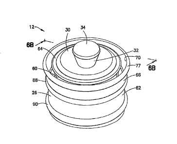
diameter D2, as shown in FIG. 6B, which is larger than the first diameter of
the first body
portion 60. A shoulder 64 extends around a perimeter of the first body portion
60 of the main
body 26. Preferably, this shoulder 64 extends in a radially outward direction
with respect to
the first body portion 60.
[0083] As stated above with respect to the description of the first
embodiment, a flexible
core member 32 is integrally formed with the main body 26 adjacent the closed
front end 30.
The flexible core member 32 includes a nose portion 34 extending from the
closed front end
30 which is adapted for contacting an interior surface 36 of an outlet
opening, such as a luer
20 of the syringe barrel 16. The flexible core member 32 may be formed from a
flexible
material and the nose portion 34 may include a semi-spherical self-centering
profile to create
a positive seal with the luer 20 at the forward end of the syringe barrel 16.
[0084] The stopper 12 of the fourth embodiment, shown in FIGS. 6A-6E, differs
from the
first embodiment in that the stopper 12 includes at least one perimetrical
skirt 66 extending
from the second body portion 62 toward the front end 30 of the main body 26.
This
perimetrical skirt 66 cooperates with the shoulder 64 for trapping air pockets
or an air bubble
68 therebetween upon insertion and/or movement of the stopper 12 within and
through the
syringe barrel 16. In this manner, upon release of a forward force on the
plunger rod 14, fluid
remaining within the syringe barrel 16 is forced through the luer 20 through
positive
displacement thereof. As shown in detail in FIGS. 6B-6D, the skirt 66 may
include an inner
surface 70 and an outer surface 72 and may be formed from a flexible and/or
elastic material
capable of deflecting radially inwardly. The inner surface 70 of the
perimetrical skirt 66 may
substantially contact the shoulder 64 to trap at least one air pocket/bubble
68. In one
embodiment, the skirt 66 includes a lip portion 74 and a tail portion 76. The
lip portion 74
may include an outwardly extending bump or first rib 77. An outer surface 77'
of the first rib
77 may be adapted for contact with an inner surface 78 of the wall of the
syringe barrel 16,
shown in FIG. 1. This first rib 77 establishes a single line of contact
between the
perimetrical skirt 66 and the inner surface 78 of the wall of the syringe
barrel 16, as shown in
FIGS. 7-9. This first rib 77 functions to keep an outer surface 69 of the
perimetrical skirt 66
adjacent the tail portion 76, positioned a predetermined distance apart from
the inner surface
78 of the wall of the syringe barrel 16. This minimizes the area of contact
between the
perimetrical skirt 66 and the syringe barrel 16 to reduce break-loose forces
and reduce static
friction of the perimetrical skirt 66 with respect to the syringe barrel 16.
The particular
17
CA 02924634 2016-03-17
design of the perimetrical skirt 66 may allow for a clearer observation of the
dose setting. In
one embodiment, the perimetrical skirt 66 has a relatively linear shape and
extends in a
cylindrical manner about the first body portion 60 of the main body 26.
According to another
embodiment, the inner surface 70 of the perimetrical skirt 66 does not
necessarily contact the
main body 26 to form the air pocket or chamber 68, but is close enough to the
main body 26
such that surface tension keeps the chamber 68 closed off and traps an air
bubble therein.
[0085] As shown in FIGS. 6B-6D, the perimetrical skirt 66 of the stopper 12 is
dimensioned to have a predetermined contact area 80 for cooperation with the
shoulder 64.
The contact area 80 is adapted for forming a predetermined gap sufficient for
trapping air and
allowing for communication of pressure from an air chamber to a fluid chamber.
[0086] FIG. 6E shows a modification of the stopper 12 of the fourth embodiment
wherein
the skirt 366 has a predetermined length Li which is less than the length L2
of the
perimetrical skirt 66 of FIGS. 6B-6D and less than the height H1 of the
shoulder 364 such
that the predetermined contact area 380 contacts a bottom surface 365 of the
shoulder 364 to
form the air pressure chamber 368.
[0087] According to another arrangement, as shown in FIG. 6F, an air pressure
chamber
468 can be created solely by the cooperation of the radially extending
shoulder 464 with the
inner surface 478 of the syringe barrel 416. In this configuration, the tip
467 of the shoulder
464 does not have to actually contact the inner surface 478 of the wall of the
syringe barrel 16
in order to create the air pressure chamber 468, but rather only needs to be
within a certain
distance with respect to this inner surface to close off the air pressure
chamber 468.
[0088] Referring again to FIGS. 6A-6F, the flexible core member 32 of the
stopper 12 of
the invention includes a front portion 82, extending above the main body 26, a
back portion
84 and a central portion 86 positioned between the front portion 82 and back
portion 84. The
flexible core member 32 is interconnected with the main body 26 and, in
particular, with the
first body portion 60 thereof via a flexible membrane 44 extending between the
central
portion 86 of the flexible core member 32 and the first body portion 60 of the
main body 26.
The inventive design of the self-centering nose portion 34 allows for a seal
to be made
between the nose portion 34 and the interior surface 36 of an outlet opening
or luer 20 when a
small amount of force is applied to the stopper 12 and over the entire
tolerance ranges of the
stopper 12 through the plunger rod 14 and syringe barrel 16. As discussed
above in relation
to the first embodiment, the partially spherical surface shape of the nose
portion 34 of the
flexible core member 32 ensures full contact between the nose portion 34 and
the interior
18
CA 02924634 2016-03-17
surface 36 of the luer 20, even when the nose portion 34 has rotated or
shifted prior to
making contact.
[0089] The flexible membrane 44 and the air pocket/bubble 68 are adapted for
storing
potential energy such that upon release of a positive pressure on the plunger
rod 14 and
release of the seal between the nose portion 34 of the flexible core member 32
and the
interior surface 36 of the luer 20, release of this potential energy forces
fluid within the
syringe barrel 16 through the luer 20 and any attached catheter.
[0090] According to
the fourth embodiment of this invention, the main body 26 includes
at least a second rib 88 extending substantially radially outward and
substantially around a
perimeter of the second body portion 62 of the main body 26. This second rib
88 is adapted
to form an active seal with the inner surface 78 of the syringe barrel 16. The
at least one air
pocket/bubble 68 is positioned in a forward position with respect to the
second rib 88. The
main body 26 may include a third rib 90 such that the second rib 88 and third
rib 90 extend
radially outward around the perimeter of the outer diameter D2, as shown in
FIG. 6B, of the
second body portion 62 of the main body 26 and arc axially spaced apart along
this second
body portion 62.
[0091] As shown in FIGS. 6B-6F and FIGS. 7-9, the main body 26 of the stopper
12 can
include at least one undercut portion 55 extending axially inward of the open
rearward end
28. This undercut portion 55 is adapted for locking the front forward end
attachment portion
31 of the plunger rod 14 within the stopper 12. According to one aspect, the
undercut portion
55 may include a reverse taper 56, as shown, for example in FIG. 7, which is
adapted for
cooperation with the front forward end attachment portion 31 of the plunger
rod 14. Various
designs of the front forward end attachment portion 31, according to the
present invention are
discussed in detail below.
[0092] As shown in FIG. 6B and FIG. 7, the main body 26 may also include an
inner
surface having a taper 198 adapted for contact with a taper 196 on the front
forward end
attachment portion 31 of the plunger rod 14. These contacting tapers 196, 198
cooperate
together such that the stopper 12 applies a radial force to the syringe barrel
16 to form an
active seal therewith upon the application of a forward force to the plunger
rod 14.
[0093] According to another aspect of the invention, as depicted in FIGS. 6C,
6D, 8, and
9, the taper 199 of the inner surface 132 of the main body 26 may be a
continuous contour
from a sidewall portion 57 of the main body 26 to the flexible core member 32.
This
continuous contour taper 199 is adapted for cooperating with taper 196 on the
front forward
end attachment portion 31 of the plunger rod 14 such that the stopper 12
applies a radial force
19
CA 02924634 2016-03-17
to the syringe barrel 16 to form an active seal therewith upon the application
of a forward
force to the plunger rod 14.
[00941 An increase in
pressure inside the syringe barrel 16 will cause the closed front end
30 of the stopper 12 to have a higher contact pressure with the inner surface
78 of the wall of
the syringe barrel 16, thereby preventing leaks at the stopper 12 and syringe
barrel 16 seal.
The active seal of the present invention solves this problem by using a lower
contact pressure
between the stopper 12 and syringe barrel 16 when there are low fluid
pressures in the
syringe barrel 16, but higher contact pressure when the fluid pressure
increases, such as
during forward movement of the plunger rod 14 and stopper 12 through the
syringe barrel 16.
[0095] In one embodiment, the active seal is achieved through the interaction
of the front
forward end attachment portion 31 of the plunger rod 14 and the inside of the
stopper 12.
According to one embodiment, as shown in FIG. 6B, the front forward end
attachment
portion 31 of the plunger rod 14 includes a forward leading surface taper 196
and
corresponds to a taper 198 on the inside of the stopper 12. During use when
the plunger rod
14 is being pushed, a forward leading edge applies force to the inside of the
stopper 12. Due
to the shape of the taper of the two surfaces 196, 198, the plunger rod 14
imparts a force that
pushes the stopper 12 forward in the syringe barrel 16 and a force that pushes
substantially
outward in a radial direction. The outward force advances the stopper 12
forward of the
second rib 88, and into the walls of the syringe barrel 16 which increases the
sealing pressure.
Likewise, as shown in FIGS. 6C and 6D, the taper 196 on the front forward end
attachment
portion 31 of the plunger rod 14 imparts a force to the continuous contour
taper 199 of the
inner surface 132 of the main body 26 such that the stopper 12 applies a
radial force to the
syringe barrel 16 to form an active seal therewith upon the application of a
forward force to
the plunger rod 14. High plunger rod forces are caused by high pressure in the
syringe barrel
16, such that contact pressure therewith will increase as pressure in the
syringe barrel 16
increases.
[0096] In a further embodiment, the perimetrical skirt 66 of the stopper 12
also acts as a lip
seal. As the fluid pressure increases, increasing the air pressure in the air
pocket/bubble 68,
the skirt contact pressure at the interface of stopper 12 and syringe barrel
16 is increased,
improving the sealing performance. Another advantage of this active seal is
due to the
application of the force of the plunger rod 14 only on the forward or second
rib 88, which
allows the back or third rib 90 to be "pulled" forward during injections. The
pulling will also
stretch the material of the back or third rib 90 reducing the effective force
on the syringe
barrel 16 and further reducing friction forces.
CA 02924634 2016-03-17
[0097] The stopper design of the present invention is intended to prevent
reflux by creating
positive displacement of fluid out of the front end of the syringe barrel (and
into any attached
catheter) after the stopper 12 has been bottomed in the syringe barrel 16 and
force is released
from the plunger rod 14. The features of the stopper 12 that act to create
this positive
displacement are the seal at the nose portion 34 of the stopper 12, the flex
or relative
movement of the stopper 12 between the nose portion 34 and the forward or
second sealing
rib 88, and potential energy in the form of pressurized fluid captured and
stored prior to the
release of the force from the plunger rod 14. The relative movement of the
second rib 88,
with respect to the nose portion 34 of the stopper 12, is achieved by means of
the flexible
membrane 44 that connects the outer forward or second rib 88, to the flexible
core member
32 and nose portion 34. The energy storing is achieved by means of both the
flexible
membrane 44 and an air bubble or air pocket 68 that is trapped under the
perimetrical skirt 66
just forward of the second rib 88.
[0098] The particular design of the fourth embodiment of the stopper 12 of the
present
invention has several advantages. For example, since the perimetrical skirt 66
may be
substantially linear, without any radial flanges, wrinkling of the
perimetrical skirt 66 is
reduced and/or eliminated. In particular, the provision of the shoulder 64 on
the first body
portion 60 of the stopper main body 26 allows the perimetrical skirt 66 to
have a relatively
straight shape and the flexibility and/or elasticity of the perimetrical skirt
66 allows for flex in
an inward direction to bring a contact area 80 of the perimetrical skirt 66,
without
deformation of the perimetrical skirt 66 itself, into contact with the
shoulder 64. Another
advantage of this design is that manufacturing of the stopper 12 is
simplified. As only one
molding tool plate is required for the bottom of the mold, the cost of the
tooling is reduced.
100991 The addition of the outwardly extending portion or bump 77 on the
perimetrical
skirt 66 minimizes the area of the perimetrical skirt 66 in contact with the
inner surface 78 of
the syringe barrel 16. This reduced contact area reduces break-loose forces
and static friction
and also provides a clear indication of the does setting. Finally, the design
of the interference
and length of the perimetrical skirt 66 is such to maintain the proper gap to
trap air and allow
for communication of pressure from the air chamber to the fluid chamber.
[00100] An active seal of the stopper 12 within the syringe barrel 16 can be
further
achieved by the front forward end attachment portion 31 of the plunger rod 14,
as described
below, in combination with the particular interior design of the stopper 12.
The front forward
end attachment portion 31 is adapted for use with any of the stopper
embodiments previously
disclosed herein. The invention is particularly useful in situations wherein
the syringe 10 is
21
CA 02924634 2016-03-17
pre-filled and sterilized and the stopper 12 is inserted into the syringe
barrel 16 prior to
attachment of the plunger rod 14 to the stopper 12.
[00101] As illustrated in FIGS. 16A-16C, the plunger rod 14 may include an
elongated
member 124 having a front end 126 and a back end 128 extending along a
longitudinal axis
AX, as shown in FIG. 16B. At least one deflecting arm 130 may be associated
with the front
end 126 of the elongated member 124. The deflecting arm 130 may be capable of
deflecting
radially inward during insertion of the plunger rod 14 into the stopper 12,
and deflecting
outward into contact with an inner surface 132 of the stopper 12, as shown in
FIG. 3, after
insertion into the stopper 12 to lock the plunger rod 14 within the stopper
12. FIGS. 16A-
16C illustrate two deflecting arms 130, however, any number of deflecting arms
130 can be
provided as needed to securely attach the plunger rod 14 within the stopper
12.
[00102] Referring back to FIG. 3, when the plunger rod 14 is inserted into the
stopper 12,
the deflecting arms 130 on the plunger rod 14 deflect ancUor the stopper 12
deforms to allow
the deflecting arms 130 to move into an undercut space 134 on the inside of
the stopper 12.
When the deflecting arms 130 enter the undercut space 134, the plunger rod 14
is locked in
place and is prevented from separating from the stopper 12. When a user uses
the syringe 10
to aspirate, the deflecting arms 130 on the plunger rod 14 will dig into the
undercut surface
136 of the stopper 12, on the inside of the stopper 12, preventing the plunger
rod 14 from
pulling out of the stopper 12. The bottom surface 133 of the deflecting arm
130 can be
tapered to correspond with the shape of the undercut surface 136 of the
stopper 12. The
deflecting arms 130 can be implemented according to several designs, as
discussed in detail
below.
[00103] According to a first embodiment, as illustrated in FIGS. 17A-1711,
the front end
126 of the elongated member 124 includes a head member 140 extending from a
front surface
144 of the front end 126. The head member 140 includes a rim member 142
extending along
a front surface 144 thereof. The deflecting arms 130 may extend from a bottom
surface 146
of the rim member 142 in a substantially downward direction. At least a first
stop member
148 may be provided for limiting deflection of the deflecting arms 130 during
insertion of the
plunger rod 14 into the stopper 12. This first stop member 148 can be
positioned adjacent to
a rearward portion 150 of the head member 140.
[00104] The rim member 142 is preferably formed from an elastomeric
material capable
of forming an active seal with an inside surface of the stopper 12, as shown
in FIG. 3. A
reinforcement material 153 may also be provided at the contact area of the
deflecting arms
130. Also, as shown in FIGS. 16A, 16C, and 17A, the rim member 142 and head
member
22
CA 02924634 2016-03-17
140 may include a hollow portion 156 defined by at least one sidewall 158. The
sidewall 158
has a plurality of inwardly extending ribs 159 extending radially inward
toward the center of
the hollow portion 156. According to one embodiment, this hollow portion 156
can come
into contact with a back portion of the flexible core member 32 inside of the
stopper 12.
[00105] According to a second embodiment, as illustrated in FIGS. 18A-18B,
the at least
one deflecting arm 160 extends radially outwardly from a center portion 162 of
the head
member 140. In this embodiment, the deflecting arm 160 may be a continuous
member that
extends through an aperture 163 in the center portion 162 of the head member
140. A hollow
portion 166 is also provided in the head member 140 and rim member 142 of this
embodiment. The edges 168 of the deflecting atm 160 may also be formed from
appropriate
reinforcement material. A first stop member 170 extends outward from a
rearward portion
150 of the head member 140. A second stop member 172 extends rearward from a
bottom
surface 173 of the rim member 142 to limit arm deflection in an opposite
direction, such as
during aspiration of the syringe 10.
[00106] According to a third embodiment, as illustrated in FIGS. 19A-19B, the
at least
one deflecting arm includes a pair of deflecting arms 174 extending in a
downward and
radially outward direction from the bottom surface 173 of the rim member 142.
In this
embodiment, a first stop member 176 extends outward from a rearward portion
150 of the
head member 140. A second stop member 178 extends downward from an outer edge
179 of
the rim member 142 for limiting deflection of the deflecting arms 174, such as
during
aspiration. The edges 180 of deflecting arms 174 are formed from appropriate
reinforcement
material.
[00107] According to a fourth embodiment, as illustrated in FIGS. 204-20C,
the front
end 126 of the elongated member 124 includes a base surface 126A having a head
member
140 extending therefrom. The head member 140 includes a rim member 142
extending along
a front surface 144 thereof. In this embodiment, the at least one deflecting
arm includes a
first arm portion 182 extending from the base surface 126A parallel with the
head member
140 and a second arm portion 184 attached to a front portion 186 of the first
arm portion 182
extending in a rearward and outward direction with respect to the first arm
portion 182. A
stop member 188, as shown in FIG. 20C, may be provided to limit deflection of
the second
arm portion 184 during insertion of the plunger rod 14 into the stopper 12.
This stop member
188 is positioned adjacent an outer surface 190 of the first arm portion 182
at a location
adjacent to an inner surface 191 of the second arm portion 184. Portions of
the second arm
portion 184 may include a reinforcement material 189 as necessary.
Additionally, the bottom
23
CA 02924634 2016-03-17
surface 193 of the second arm member 184 may be flat or tapered as desired,
depending upon
the shape of the mating surface undercut portion 136 of the stopper 12.
[00108] These double deflecting arm portions 182, 184 can deflect from the
base of the
front end of the plunger rod 14 and from the top of the arm attached to the
base of the front
end geometry. During insertion, a normal load is exerted on the outside
surface of the second
arm portion 184. When the pressure is exerted at the top or front portion 186
of the second
arm portion 184, first arm portion 182 deflects inwardly. As the pressure
moves down the
surface of second arm portion 184, this second arm portion 184 will begin to
deflect.
Deflection is greatest when both arm portions 182, 184 are at maximum
deflection. During
aspiration, a compressive and/or torsional load is exerted on the arm portions
182, 184 and
the first arm portion 182 will begin to deflect inwards while second arm
portion 184 digs into
a stopper undercut surface, such as undercut surface 136, as shown in FIG. 3.
Deflection,
however, is limited by the contact between arm second arm portion 184 and the
inner surface
132 of the wall of the stopper 12. As discussed above, a stop member 188 may
be provided
for reducing stresses on the arm portions 182, 184 by limiting the deflection
of the arm
portions 182, 184 where necessary, making deflection independent of the
surface pressure
during insertion and after the stop member 188 and second arm portion 184 are
in contact
with each other.
[00109] The FIGS. 20A-20C embodiment can also include an opening 192 in the
head
member 140 and rim member 142. This opening 192 is defined by a circular
sidewall 194
and a plurality of ribs 195 extending inwardly from this circular sidewall 194
toward the
opening 192.
[00110] According to a
fifth embodiment, as illustrated in FIGS. 21A-21F, the attachment
portion, generally indicated as 200, of the plunger rod 14 can include a
deflecting arm 204
which can include a single circular deflecting arm or a plurality of
deflecting arms extending
from the front end 126 of the elongated member 124. This deflecting arm 204
defines a
space 206, and during attachment of the plunger rod 14 within the stopper 12,
the deflecting
arm 204 deflects inwardly toward the space 206. When the deflecting arms 204
have reached
maximum deflection and are housed in the undercut space 134 on the inside of
the stopper
12, a slug 208 may be is inserted into this space 206 to support the
deflecting arm 204 and
prevent it from collapsing and separating from the stopper during use of the
syringe 10.
According to one embodiment, as illustrated in FIGS. 21D-21E, the elongated
member 124
includes a hollow portion 210 and the slug 208 is pre-molded within this
hollow portion 210.
After the attachment of the plunger rod 14 to the stopper 12, an application
force is applied
24
CA 02924634 2016-03-17
within the hollow portion 210 to force the slug 208 into the space 206.
Alternatively, the slug
208 may be separately molded and subsequently inserted.
[001111 Another aspect of the present invention is a new plunger body design
as shown in
FIGS. 22A-22B, 23A-23B, 24A-24B, and 25. The plunger rod 14 is preferably made
of a
rigid thermoplastic material. This design, as discussed in detail below,
consists of a hollow
elongated plunger rod body wherein the hollow portion is defined by a
plurality of
longitudinally extending lobes and preferably an odd number of lobes are
provided. In
traditional solid body four rib plunger designs, a user may apply a side load
during aspiration
that may be normal to the edge of a rib, causing minimal side loading
deflection, or normal to
the region in between the ribs, i.e., 45 from the rib, causing maximum side
loading
deflections. The present invention introduces a plunger body comprising an
elongated body
portion 234 having a front end 236, a back end 238, and a sidewall portion 239
extending
along a longitudinal axis between the front end 236 and the back end 238. The
sidewall
portion 239 comprises a plurality of longitudinally extending lobes 240
defining an interior
hollow portion 242. An attachment member 244 is secured to the front end 236
and is
adapted for attachment of the plunger rod 14 to the stopper 12. A cover member
246 is
secured to the back end 238 of the elongated body portion 234 for covering the
interior
hollow portion 242 and providing a thumb press area 248 for application of a
force to the
plunger rod 14 during use.
[00112] The longitudinally extending lobes 240 preferably comprise an odd
number of
lobes spaced substantially equidistant with respect to one another. According
to one
embodiment, as shown in FIGS. 23A-23B, the plurality of longitudinally
extending lobes
240 comprises a three lobe design 250 positioned at approximately 120 with
respect to one
another. According to still another embodiment, as shown in FIGS. 22A-228, the
plurality
of extending lobes 240 number at five, forming a five lobe design 251 wherein
the lobes 240
are spaced substantially equidistant with respect to one another. The lobes
are positioned
with respect to one another to form substantially uniform side loading
deflection of the
plunger rod 14. Providing an odd number of lobes 240 decreases the expected
deflection
when a load is applied to the region between the lobes 240 by introducing a
lobe on the
opposite side which supports the reaction load. The present invention also
includes four lobe
240 hollow elongated plunger body designs 252, such as illustrated in FIGS.
24A-24B.
Because the body portion of the plunger 14 includes a hollow portion 253, the
advantages
associated with the hollow design, as discussed above, would also be present
in the four lobe
CA 02924634 2016-03-17
design 252. The hollow design also provides additional stiffness to the body
portion 234 of
the plunger rod 14 and several ergonomic improvements, such as reduced product
costs,
easier manufacturing procedures, and the like as discussed in detail below.
[00113] The plunger rod 14 of the invention may be manufactured according to
the
following processes. In a first process, the elongated body portion 234 and
the front end
attachment member 244 are integrally molded from the same material. The
plunger rod 14 is
designed to have an interior hollow portion 242 so that a core pin can be
driven up the center
of the plunger rod 14 during injection molding. This allows the plunger rod 14
to be molded
"standing up", which results in a reduction in cycle time due to additional
cooling in the core
pin and an increase in volume due to an increase in cavity number. To cover
the core pin
opening or interior hollow portion 242 on the thumb press side/area 248, a
soft-touch surface
disk 249 may be attached to the thumb press area 248 for added comfort during
injection.
[00114] According to a second process, as shown in FIG. 25, the plunger rod 14
can be
manufactured in three separate pieces. The attachment member 244 can be
injection molded,
the elongated body portion 234 of the plunger rod 14 can be extruded or
injection molded,
and the cover member or thumb press disk 246 can be manufactured by a stamp
molding
process. The attachment member 244, elongated body portion 234, and thumb
press disk 246
can be formed from different materials for improved performance where needed.
For
example, a more expensive material may be used to mold the front attachment
member 244
for improved performance and a soft touch elastomer may be used for the thumb
press disk
246. Extruding the body portion 234 of the plunger 14 allows for additional
cross section
geometries that would provide uniform side loading deflection and allow for
ergonomic
improvements that would other wise be limited by parting lines on the mold.
Additionally,
using an extrusion process for the body portion allows for the production of
body portions of
different lengths for use with different length syringe barrels 16 from a
single extrusion
device.
[00115] In the attachment arrangements of FIGS. 17A-17B, 18A-18B, 19A-19B, and
20A-
20C, each of these embodiments include a head member 140 having a rim member
142
extending along a front surface 144 thereof wherein the rim member includes a
taper 196
adapted for contacting a corresponding taper 198, within the stopper 12, as
shown in FIG. 2B
for applying a radial force to the stopper 12 upon the application of a
forward force to the
plunger rod 14. In the FIG. 21A-21F arrangement, the deflecting arm 204
includes a taper
213 at a forward end 214 thereof adapted for contacting a corresponding taper
198 within the
26
CA 02924634 2016-03-17
stopper 12 for applying a radial force to the stopper 12 upon the application
of a forward
force to the plunger rod 14.
[00116] The stopper design of the present invention is intended to prevent
reflux by
creating positive displacement of fluid into the attached catheter after the
stopper 12 has been
bottomed in the syringe barrel 16 and force is released from the plunger rod
14. The features
of the stopper 12 that act to create this positive displacement are the seal
at the nose portion
34 of the stopper 12, the flex or relative movement of the stopper 12 between
the nose portion
34 and the forward or first sealing rib 46, and a means by which potential
energy in the form
of pressurized fluid can be captured and stored prior to the release of the
force from the
plunger rod 14. The relative movement of the first rib 46 with respect to the
nose portion 34
of the stopper 12 is achieved by means of the flexible membrane 44 that
connects the outer
first rib 46 to the flexible core member 32 and nose portion 34. The energy
storing is
achieved by means of both the flexible membrane 44 and the air bubble or air
pocket
chamber 53 that is trapped under the folded forward extending skirt 50 just
forward of the
first rib 46.
1001171 As illustrated in FIGS. 10-12, positive displacement or a method of
preventing
reflux within the syringe barrel includes the following steps. The first step
provides a stopper
12 having a main body defining an open rearward end 28 and a closed front end
30. The
open rearward end 28 is adapted to receive a front forward end attachment
member 31 of a
plunger rod 14 therein. A flexible core member 32 is interconnected with the
main body 26
via a flexible membrane 44 integrally formed with the main body 26 adjacent
the closed front
end 30. The flexible core member 32 includes a nose portion 34, preferably
having a profile,
as discussed above, which is self-centering and adapted to create a positive
seal with an
interior surface of the luer 20 of the syringe barrel 16. The method further
includes the step
of inserting the front forward end attachment member 31 of the plunger rod 14
within the
open rearward end 28 of the stopper 12. Applying a force to the plunger rod 14
to advance
the stopper 12 into the syringe barrel 16 until the nose portion 34 of the
flexible core member
32 contacts the interior surface 36 of the syringe barrel luer 20 forming a
seal and trapping
fluid from flowing into the luer 20. Applying additional force to the plunger
rod 14 to
compress the nose portion 34, advances the at least one rib 46 within the
syringe barrel 16
and compresses the trapped air to form increased pressure within the air
pocket 53. The final
step of the method comprises releasing the force on the plunger rod 14 to
release the seal
between the nose portion 34 and the interior surface 36 of the luer 20 wherein
friction force
maintains the rib 46 in an advanced position within the syringe barrel 16 such
that the
27
CA 02924634 2016-03-17
increased pressure within the air pocket 53 causes any trapped fluid to be
pushed through the
luer 20 and any attached catheter.
[00118] FIGS. 2A-2B and
3 show a stopper design wherein the stopper 12 includes at
least one forward extending skirt 50 extending from a closed front end 30 of
the main body
26 and wherein the step of applying a force to advance the stopper 12 into the
syringe barrel
causes this skirt 50 to deflect inward with respect to the main body 26 of the
stopper 12 to
substantially contact, or to within a predetermined distance with respect to
an outer portion
52 thereof, to form an air pocket 53 for trapping air therein. The step of
applying additional
force to the plunger rod 14 to compress the nose portion 34 causes the
flexible membrane 44
to stretch. The step of releasing the force on the plunger rod 14, thereby
releases the force on
the flexible membrane 44, causing any trapped fluid to be pushed through an
outlet opening
or luer 20 and any attached catheter.
[00119] FIGS. 4A and 4B show a stopper design which does not rely on a
flexible skirt to
trap an air bubble to assist in storing energy to force any trapped fluid
through the luer 20.
Rather, this design only relies on the flexibility of the membrane 44A
connecting the flexible
core member 32 to the main body 26 of stopper 12 to capture pressure energy
and return it
once force is released from the plunger rod 14. Additional features that can
trap an air bubble
include other forms of molded-in pockets or slotted channels in the stopper
face.
[00120] FIGS. 5A and 5B illustrate yet another design of the stopper 254,
according to the
invention. This design, discussed in detail above, shows a lip seal for
sealing against the
barrel. The front seal 256 of the stopper 254 is located on the leading edge
of flexible arm
258. The initial sealing pressure is generated by the arm's interference with
the barrel wall.
When the pressure in the syringe barrel 16 increases, an outward radial force
is applied to the
inside 259 of the flexible arm 258. This outward push will increase the force
with which the
seal presses against the barrel wall.
[00121] A method of positively displacing fluid and preventing reflux within a
syringe
barrel utilizing the stopper design of FIG. 6C is also provided by the present
invention and is
illustrated in FIGS. 13-15. This method comprises the steps of providing a
stopper 12
comprising a main body 26 having a closed front end 30. The main body 26 may
also
include an open rearward end 28 which is adapted to receive a front thrward
end attachment
member 31 of a plunger rod 14 therein. The main body 26 includes a first body
portion 60
having a first diameter and a second body portion 62 having a second diameter
which is
larger than the first diameter of the first body portion 60. A flexible core
member 32 is
integrally formed with the main body 26 adjacent the closed front end 30. The
flexible core
28
CA 02924634 2016-03-17
member 32 includes a nose portion 34 extending from the front end, a shoulder
64 extending
around the first body portion 60 of the main body 26, and at least one
perimetrical skirt 66
extending from the second body portion 62 toward the front end 30 of the main
body 26. The
perimetrical skirt 66 cooperates with the shoulder 64 for trapping at least
one air
pocket/bubble 68 therein. The perimetrical skirt 66 includes a radially
extending bump or
first rib 77 along an outer surface lip portion 74. The method further
comprises the steps of
providing at least a second rib 88 extending radially outward around a
perimeter of an outer
diameter portion or second body portion 62 of the main body 26, inserting the
front forward
end attachment member 31 of a plunger rod 14 within the open rearward end 28
of the
stopper 12, applying a force to the plunger rod 14 to advance the stopper 12
into the syringe
barrel 16 until the nose portion 34 of the flexible core member 32 contacts
the back or
interior surface 36 of an outlet opening, such as a luer 20, forming a seal
and trapping fluid
from flowing into the luer 20, applying additional force to the plunger rod 14
to compress the
nose portion 34, advancing the second rib 48 within the syringe barrel 16 and
compressing
the trapped air to form increased pressure within the air pocket 68. Upon
completion of the
flushing operation, the method includes the step of releasing the force on the
plunger rod 14
to release the seal between the nose portion 34 and the interior surface 36 of
the luer 20
wherein friction force maintains the second rib 48 in an advanced position
within the syringe
barrel 12 such that the increased pressure within the air pocket 68 causes any
trapped fluid to
be pushed through the luer 20 and any attached catheter. When the seal is
lost, the pressure
and stored energy in the air pocket/bubble 68 is released. This air
pocket/bubble 68 will
expand forcing fluid out from in the front of the stopper 12. This release of
pressure pushes
outward through the luer 20 causing fluid to be pushed out through any
attached catheter.
[00122] The nose portion 34 of the flexible core member 32 has a profile
adapted to create
a positive seal with the interior surface of the luer 20 of the syringe barrel
16. This core
member 32 is interconnected with the main body 26 via a flexible and/or
elastic membrane
44. The step of applying additional force to the plunger rod 14 to compress
the nose portion
34 causes the flexible membrane 44 to stretch and the step of releasing the
force on the
plunger rod 14 releases this force on the flexible membrane 44 to cause any
trapped fluid to
be pushed through the luer 20 and any attached catheter preventing reflux
within the syringe
barrel 16.
[00123] The present
invention has numerous advantages over existing plunger rod and
stopper designs. In one aspect of the invention, reduced break-loose forces
are present when
the stopper 12 is first advanced which increases the ease of use of the device
and reduce the
29
CA 02924634 2016-03-17
release that occurs when the stopper 12 is first broken loose. The present
designs also
improve or reduce the sustaining forces on the stopper 12 due to reduced
interference
between the stopper 12 and the syringe barrel 16 due to the active seal, which
allows the
plunger rod 14 and stopper 12 assembly to be used in a wider variety of
syringe pump
applications. Still another advantage of the inventive assembly is the
improved connection
between the plunger rod 14 and the stopper 12, especially when the stopper 12
is inserted into
the syringe barrel 16 before the plunger rod 14 is attached to the stopper 12.
Previous
designs, which used a threaded connection, tended to deform the stopper or
push it off center,
increasing the chance of leakage. Finally, the inventive design achieves a
positive
displacement of the fluid after the plunger rod 14 is bottomed and the force
on the plunger
rod 14 is released.
[00124] While specific embodiments of the invention have been described in
detail, it will
be appreciated by those skilled in the art that various modifications and
alternatives to those
details could be developed in light of the overall teachings of the
disclosure. Accordingly, the
particular arrangements disclosed are meant to be illustrative only and not
limiting as to the
scope of invention which is to be given the full breadth of the claims
appended and any and
all equivalents thereof.