Note: Descriptions are shown in the official language in which they were submitted.
-1-
HEAT EXCHANGING SYSTEM AND METHOD FOR
A HEAT RECOVERY STEAM GENERATOR
BACKGROUND ART
Natural gas serves as the energy source for much of the currently generated
electricity. To this end, the gas undergoes combustion in a gas turbine which
powers
an electrical generator. However, the products of combustion leave the gas
turbine
as an exhaust gas quite high in temperature. In other words, the exhaust gas
represents an energy source itself. This energy is captured in a heat recovery
steam
generator ("HRSG") that produces superheated steam that powers another
electrical
generator.
Such exhaust gas includes carbon dioxide and water in the vapor phase, but
also includes traces of sulfur in the form of sulfur dioxide and trioxide.
Those sulfur
compounds, if combined with water, produce sulfuric acid which is highly
corrosive.
As long as the temperatures of the heating surfaces remain above the acid dew
point
temperature of the exhaust gas, SO2 and S03 pass through the HRSG without
harmful effects. But if any surface drops to a temperature below the acid dew
point
temperature, sulfuric acid will condense on that surface and corrode it.
Dew point temperatures vary depending on the fuel that is consumed. For
natural gas the temperature of the heating surfaces should not fall below
about
140 F. For most fuel oils it should not fall below about 235 F
Generally, an HRSG comprises a casing having an inlet and an outlet and a
succession of heat exchangers¨namely a superheater, an evaporator, and a
feedwater heater arranged in that order within the casing between the inlet
and
outlet.
Such heat exchangers for an HRSG can have multiple banks of coils, the
last of which in the direction of the gas flow can be a feedwater heater.
Surfaces
vulnerable to corrosion by sulphuric acid do exist on the feedwater heater.
The
CA 2924657 2019-10-24
CA 02924657 2016-03-17
WO 2015/048029
PCT/US2014/057005
-2-
feedwater heater receives condensate that is derived from low-pressure steam
discharged by the steam turbine, and elevates the temperature of the water.
Then
the warmer water from the feedwater heater flows into one or more evaporators
that
convert it into saturated steam. That saturated steam flows on to the
superheater
which converts it into superheated steam. From the superheater, the
superheated
steam flows to the steam turbine.
In this process, by the time the hot gas reaches the feedwater heater at the
back end of the HRSG, its temperature is quite low. However, that temperature
should not be so low that acids condense on the heating surfaces of the
feedwater
heater.
Generally, in the above-discussed process, most HRSGs produce
superheated steam at three pressure levels ¨ low pressure (LP), intermediate
pressure (IF) and high pressure (HP). Further, an HRSG can have what are
termed
an LP Evaporator, an HP Economizer, and an IF Economizer. The feedwater heater
typically discharges some of the heated feedwater directly into an LP
evaporator.
A feedwater heater, or preheater, in a steam generator extracts heat from low
temperature gases to increase the temperature of the incoming condensate
before it
goes off to the LP evaporator, HP economizer, or IF economizer. Multiple
methods
have been used to increase the temperature of the condensate before it enters
any
part of the preheater tubes within the gas path (e.g., recirculation pump,
external
heat exchanger). These methods are used to prevent the exhaust gas temperature
from dropping below the acid dew point and causing sulfuric acid corrosion.
Prior systems and methods have been limited in application because the
feedwater temperature was not high enough to protect against dew point
corrosion of
all fuels. The movement of the heat transfer coils to the hotter regions
provides for
higher differentials in the heat exchanger.
In the present disclosure, an external water-to-water heat exchanger heats
the lower temperature inlet condensate with the source of heat being hot water
that
is exiting the first stage of the feedwater heater. The condensate flow first
enters the
external heat exchanger. Thereafter preheated condensate leaves the external
heat
exchanger and enters the feedwater heater. Water energy exiting the preheater
is
used to preheat the incoming condensate. The present disclosure places a
section
of a preheater surface into a hotter section of the gas flow, upstream of the
LP
CA 02924657 2016-03-17
WO 2015/048029
PCT/US2014/057005
-3-
evaporator, to achieve the beneficial result of increasing source inlet
temperature
and directly increasing the outlet temperature of the preheated condensate
exiting
the external heat exchanger. This arrangement allows the use of an external
heat
exchanger in designs with higher dew points in the cold end. The present
system
and method can thus create a larger temperature differential in the external
water-to-
water heat exchanger. This larger temperature differential than present in the
prior
art, yields a higher outlet temperature and protects the HRSG from cold end
condensation corrosion from fuels with higher acid dew points.
The foregoing and other features and advantages of the invention as well as
presently preferred embodiments thereof will become more apparent from the
reading of the following description in connection with the accompanying
drawings.
BRIEF DESCRIPTION OF DRAWINGS
Fig. 1 is a schematic view of a power system that uses an heat recovery
steam generator ("HRSG") provided with inventive features;
Fig 2 is a sectional view of a novel HRSG;
Fig. 3 is a schematic view of elements of a novel HRSG;
Fig. 4 is a schematic view of elements of another embodiment of the novel
HRSG; and
Fig. 5 is a schematic view of elements of another embodiment of the HRSG.
Corresponding reference numerals indicate corresponding parts throughout
the several figures of the drawings.
BEST MODE FOR CARRYING OUT THE INVENTION
The following detailed description illustrates the claimed invention by way of
example and not by way of limitation. The description clearly enables one
skilled in
the art to make and use the disclosure, describes several embodiments,
adaptations,
variations, alternatives, and uses of the disclosure, including what is
presently
believed to be the best mode of carrying out the claimed invention.
Additionally, it is
to be understood that the disclosure is not limited in its application to the
details of
construction and the arrangements of components set forth in the following
description or illustrated in the drawings. The disclosure is capable of other
embodiments and of being practiced or being carried out in various ways. Also,
it is
to be understood that the phraseology and terminology used herein is for the
purpose of description and should not be regarded as limiting.
-4-
The inventive disclosures are now provided for a heat exchanging system
and method for use in an HRSG. An overall illustration of a system which
features
use in a heat-recovery steam generator (HRSG) appears in U.S. Patent No.
6,508,206 B1 (hereafter "'206 Patent"). Fig. 1 of the present application
shows a
layout similar to that shown in Fig. 3 of the '206 Patent. Fig. 1 hereof
discloses a
gas turbine G that discharges hot exhaust gases into an HRSG 50, which
extracts
heat from the gases to produce steam to power a steam turbine S. The gas
turbine
G and steam turbine S power the generators E that are capable of producing
electrical energy. The steam turbine S discharges steam at a low temperature
and
pressure into a condenser 51 where it is condensed into liquid water. The
condenser
51 is in flow connection with a condensate pump 52 that directs the water back
to
the HRSG 50 as feedwater.
The disclosure of the present inventive features of the present application
show an HRSG 50 with an arrangement of heat exchangers and flow channels that
provide improvements over the prior art.
With reference to Figs. 1 and 2 of the present application, the HRSG 50 has
a casing 53 within which are heat exchangers. Hot gases, such as discharged
from
a gas turbine, enter the casing 53 and pass through a duct 54 having an inlet
56 and
an outlet 59. During that process, that gas passes through heat exchangers.
The casing 53 generally will have a floor 61 over which the heat exchangers
are supported, and sidewalls that extend upwardly from the floor 61. Typically
the
top of the casing 53 is closed by a roof 63. The floor 61 and roof 63 extend
between
the sidewalls so that the floor 61, sidewalls and roof 63 help to form the
duct 54.
From outlet 59 the gas can flow through flu 67.
Generally, the heat exchangers comprise coils that have a multitude of tubes
that usually are oriented vertically and arranged one after the other
transversely
across the interior of the casing 53. The coils are also arranged in rows
located one
after the other in the direction of the hot gas flow depicted by the arrows in
Fig. 3 of
the present application. The tubes contain water in whatever phase its coils
are
designed to accommodate. The length of the tubes can be as great as 80' tall.
Now attention is directed to the arrangement of the heat exchangers shown
in Fig. 2. The general description for Fig. 2 will be given with an
orientation of moving
CA 2924657 2019-10-24
CA 02924657 2016-03-17
WO 2015/048029
PCT/US2014/057005
-5-
from the inlet 56 to the outlet 59, or from the left to the right looking at
Fig. 2.
Generally, reference character 70 represents what are termed "Upstream Coils"
in
an HRSG. For example, such Upstream Coils can include what are referred to in
the
'206 Patent, as a superheater designated by reference character 16 in the '206
Patent that converts saturated steam to superheated steam; followed by at
least one
evaporator such as a high-pressure evaporator ("HP Evaporator") shown as 18 in
the
'206 Patent; thence followed by a high-pressure economizer ("HP Economizer").
The HP Economizer is shown as a group of coils immediately to the right of the
evaporator designated 18, and shown in Fig. 4 of the '206 Patent. Hence the
term
"Upstream Coils 70' generally refer to all of the Superheater, HP Evaporator
and HP
Economizer. The amount of the space devoted to such components in the HRSG
can depend upon the desired characteristics and performance of the HRSG 50.
Downstream from the Upstream Coils 70, the novel arrangement has a
preheater booster 74. As will be discussed, the preheater booster 74 provides
for a
feedwater heater presence in a hotter region of the HRSG to facilitate return
feeding
therefrom to a heat exchanger that feeds water to other parts of the feedwater
heater.
Continuing the description from upstream to downstream, left to right in Fig.
2,
downstream from preheater booster 74 appears a low pressure evaporator 77 ("LP
Evaporator"). Thence downstream from the LP Evaporator is what is generally
designated a feedwater heater 80.
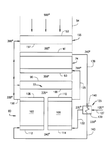
Now, with more specific reference to the schematic view of Fig. 3, the
preheater booster 74 comprises a coil having an upstream face 90 and a
downstream face 93. The exhaust gases flow into the upstream face 90 through
the
coil and thence through the downstream face 93 to leave the preheater booster
74.
As seen in the Fig. 3 schematic, the LP Evaporator 77 has an upstream face
96 and a downstream face 100. The exhaust gas leaves the preheater booster 74
thence flows into the LP Evaporator 77 front face 96, through the LP
Evaporator 77,
and through the LP Evaporator's downstream face 100 toward the feedwater
heater
80.
The feedwater heater 80 has two sections 103 and 106, which can be
arranged side by side in the duct 54, as shown in Fig. 3. Sections 103 and 106
each
have an upstream face 108 and 110, respectively. The exhaust gases flow into
the
CA 02924657 2016-03-17
WO 2015/048029
PCT/US2014/057005
-6-
upstream faces 108 and 110, then through the coils of sections 103 and 106
respectively, thence exit through the downstream faces 112 and 114,
respectively.
From there, the exhaust gases can flow through outlet 59 and exit flu 67.
Focusing now on the flow of water among aforementioned components of the
arrangement, a water-to-water heat exchanger 125 is illustrated as located to
the
exterior of the duct 54. The condensate pump 52 discharges feedwater into a
supply
pipe 127, which delivers that feed water into the inlet of the low temperature
path
130 of heat exchanger 125. The feedwater leaves the low temperature path 130
in
exchanger 125 at its outlet and flows into a connecting pipe 132 which acts as
a
conduit. Pipe 132 delivers the feedwater to the tubes at the downstream face
114 of
section 106. The water leaves the section 106 at its upstream face 110 and
flows
through a transfer pipe 135 which serves as a conduit to connect with the
inlet of the
preheater booster 74 coil at its downstream face 93. The water flows thence
through
preheater booster coil 74 toward the upstream side thereof to exit the
preheater
booster coil 74 at its upstream face 90. From there, it flows into a transfer
pipe 138
which acts as a conduit to connect with the inlet of the high temperature path
140 of
heat exchanger 125.
Within the high temperature path 140 of heat exchanger 125 the temperature
of the water decreases since it loses heat to water in the low temperature
path 130.
.. At the outlet of the high temperature path 140, the water enters transfer
pipe 143
which acts as a conduit to be delivered to the section 103 at its downstream
face
112. The water thence flows through section 103 to exit therefrom at its
upstream
face 108 whereby the temperature of the water is raised, to thence pass
through a
discharge pipe 150. Pipe 150 acts as a conduit and extends to connect with the
LP
Evaporator 77 at its downstream face 100. From the upstream face 96 of LP
Evaporator 77, the water can flow, for example, to the HP Economizer.
Now the system will be discussed with exemplary temperatures. The exhaust
gases from the gas turbine "G", enter the upstream face 153 of the last of the
Upstream Coils 70, here designated, for example, as a high pressure (HP)
economizer 155. The gases enter the HP Economizer upstream face 153 at a
temperature of about 500 F. The exhaust gases exit the downstream face of HP
Economizer 155 at a temperature of about 380 F, and enter the upstream face 90
of
preheater booster 74 at about that same temperature.
CA 02924657 2016-03-17
WO 2015/048029
PCT/US2014/057005
-7-
Fig. 3 shows water leaving both of the upstream faces 108 and 110 of
feedwater heater sections 103 and 106, respectively, at about 300 F. From the
upstream face 110 of section 106, the water passes through pipe 135 to enter
the
downstream face 93 of preheater booster 74 at about 300 F. That fluid leaves
the
preheater booster upstream face 90 through pipe 138 at about 340 F. Through
pipe
138, the water then flows into the high temperature path 140 of the heat
exchanger
125 at about 340 F.
Water from the condensate pump 52 discharges water at about 120 F, which
enters the heat exchanger 125 through pipe 127 at about the same temperature.
Now a review of the temperatures of the water flowing into and leaving the
feedwater heater sections 103 and 106 is given. Fig. 3 shows that the water
from the
low temperature path of heat exchanger 125 feeds into the pipe 132 at about
230 F.
From there, the water enters feedwater heater section 106 at its downstream
face
114 at about 230 F. The water then passes through section 106 to exit at its
upstream face 110 into pipe 135 at a temperature of about 300 F
Turning now to the feedwater heater section 103, the temperature of water
exiting the heat exchanger high temperature path 140 enters pipe 143 at about
230 F. From there it enters the downstream face 112 of section 103 at about
230 F.
Thus the water temperature entering both downstream faces 112 and 114 of
sections 103 and 106 is about 230 F.
The water entering section 103 exits at its upstream face 108 at the
temperature of about 300 F to pass through pipe 150 into LP Evaporator 77 at
that
temperature. Pipe 150 can also have a branches feeding off of it at 300 F to
the
downstream face 157 of HP Economizer 155. Additionally, depending on the
arrangement of coils of a particular HRSG, water feeding off the upstream face
108
of section 103 can also flow at 300 F to the downstream face of other coils
located
upstream of preheater booster 74, such as to the downstream face of an
intermediate pressure (IF) Economizer.
The temperature of the hot gas exiting the downstream face 100 of LP
Evaporator 77 and entering at the upstream faces 108 and 110 of feedwater
heater
sections 103 and 106 is about 335 F. The temperature of the hot gas exiting
the
feedwater heater sections 103 and 106, at their respective downstream faces
112
and 114, is about 240 F.
CA 02924657 2016-03-17
WO 2015/048029
PCT/US2014/057005
-8-
Thus the surfaces of the tubes making up feedwater heater sections 103 and
106 are maintained to be about 240 F or higher. This temperature is higher
than the
aforementioned dew point for condensation of sulphuric acid. Thus
the
condensation of sulfuric acid on the surfaces of the tubes making up the
sections
103 and 106 will be resisted with the present design.
The gases leave the downstream preheater booster face 93 at a temperature
of about 350 F, and enter the upstream face 96 of the LP Evaporator 77 at
about
that 350 F temperature. The gases exit the LP Evaporator downstream face 100
at
a temperature of about 335 F.
Feedwater from the condenser 51 can be discharged at approximately 120 F
through the supply pipe 127 into the low temperature path 130 of the heat
exchanger
125.
The water leaving the heat exchanger 125 through the high temperature path
exits at 230 F and flows into section 103 at its downstream face 112 at a
temperature of about 230 F.
With the present design the heat exchanger designated 125 does not require
recirculation, and thus a recirculation pump and its attendant overhead and
expense
is not required for the heat exchanger. Further, with the present design there
is no
need to bypass any section of feedwater heater 80.
Also, with the present arrangement, the water temperature feeding into the LP
Evaporator 77 from the feedwater preheater 80 enters at a temperature of 300 F
as
compared to 250 F with a temperature of water feeding into an LP Evaporator of
a
prior art system. Moreover, in the present system, water temperature of 300 F
feeding from the feedwater heater section 103 to the HP Economizer 155 or
other
economizer located upstream of the LP Evaporator, compares favorably to the
water
input temperature of 250 F to HP Economizers and/or IF Economizers in a prior
art
design.
Now attention is directed to the modification of Figure 4. Figure 4 can
include
some of the same elements as Figure 3. Figure 4 shows HRSG hot gas flow in a
direction from the inlet, indicated by arrows, through the upstream face 153'
of an HP
Economizer 155', through HP Economizer 155' and its downstream face 157', as
described for Figure 3. Thence the hot gas flows to the upstream face 90' of a
preheater booster 74', though booster 74' and its downstream face 93' toward
and
CA 02924657 2016-03-17
WO 2015/048029
PCT/US2014/057005
-9-
thorough the front face 96' of LP Evaporator 77'. The hot gas passes through
the
coil of LP Evaporator 77' and through its downstream face 100'.
Instead of the two feed water heater sections 103 and 106 described
regarding Figure 3 which are placed generally side by side, the feed water
heater 80'
of Figure 4 has its sections containing coils arranged from front to rear, or
upstream
toward downstream, in series fashion. Feedwater heater 80' has a section 210
which is located farthest upstream of the three sections, with a second
intermediate
section 213 positioned downstream there from. Then downstream from second
section 213 is the farthest downstream section, i.e., the third section 216.
Each of
sections 210, 213 and 216 have pairs of corresponding upstream faces and
downstream faces 218 and 220, 222 and 224, and 226 and 228, respectively.
In Figure 4, a water to water heat exchanger 125' located exterior of duct
54',
is similar to the exchanger 125 of Figure 3. In Fig. 4, condensate pump 52
discharges feedwater though a supply pipe 227 into the low temperature path
231 of
the heat exchanger 125'. The feedwater leaves the low temperature path 231 of
exchanger 125' to flow into connecting pipe 232.
Pipe 232 delivers the feedwater to the downstream face 228 of feedwater
heater section 216. The water leaves section 216 at its upstream face 226 to
flow
through a transfer pipe 246 to connect with the inlet of section 210 at its
downstream
face 220. The water flows through the coil of section 210 to thence leave its
upstream face 218 to flow into a transfer pipe 252. From pipe 252, the water
flows to
preheater booster 74' at its downstream face 93'. The water then passes
through
preheater heater booster 74' to exit preheater booster stream face 90' into a
transfer
pipe 255. Thence the water flows through pipe 255 to connect with the inlet of
the
high temperature path 258 of heat exchanger 125'.
Within the high temperature path 258 of heat exchanger 125', the temperature
of the water decreases since it loses heat to water in the low temperature
path 231.
At the outlet of the high temperature path 258, the water enters transfer pipe
261 to
feed into feedwater heater section 213 at its downstream face 224. The water
flows
.. through section 213 to exit therefrom at its upstream face 222, whereby the
temperature of the water is raised, to then pass into a discharge pipe 264.
Pipe 264
extends to connect with LP Evaporator 77' at its downstream face 100', to be
heated
CA 02924657 2016-03-17
WO 2015/048029
PCT/US2014/057005
-10-
therein. From the LP Evaporator 77', the water can flow from its upstream face
96',
to the HP Economizer, for example.
Now, as with the Fig. 3 embodiment, the Fig. 4 embodiment will be discussed
with exemplary temperatures. Description of the hot gas airflow through the HP
Economizer 155' and through preheater booster 74' is similar to that described
for
Fig. 3 with the various pipes described acting as conduits. Exhaust gases from
gas
turbine "G", enter the upstream face 153' of the last of the Upstream Coils,
here
designated, for example, as HP Economizer 155. The gases enter the HP
Economizer upstream face 153' at a temperature of about 500 F. Then the
exhaust
gases exit the HP Economizer face 157' at about 380 F, to next enter the
upstream
face 90' of preheater booster 74' at about that same temperature, and pass
through
booster 74' and its downstream face 93' at about 350 F. The hot gas then flows
at
about 350 F through LP Evaporator 77' and exits its downstream face 100' at
about
335 F.
Turning now to the most upstream of the feedwater heater sections, water
leaves upstream face 218 of section 210, at a temperature of about 300 F. Then
the
water passes through pipe 252 to enter the downstream face 93' of preheater
booster 74' at about 300 F. That water then passes through preheater booster
74' to
its upstream face 90', to next exit through pipe 255 at about 340 F. The water
then
flows through pipe 255 into the high temperature path 258 of heat exchanger
125' at
a temperature of about 340 F.
Water from the condensate pump 52 discharges water at about 120 F into the
heat exchanger 125' through pipe 227 at about that same temperature. Now a
review of the temperatures of the water as it leaves the heat exchanger 125'
is given.
The water from the low temperature path 231 of heat exchanger 125' feeds into
the
pipe 232 at a temperature of about 230 F. From there, the water at about 230 F
enters the most downstream of the feedwater heater sections, section 216, at
its
downstream face 228. The water then passes through section 216 to enter its
upstream face 226 into discharge pipe 246 at about 250 F. Through pipe 246 the
water then enters feedwater section 210 at its downstream face 220 at about
250 F.
The water then flows through section 210 and exits at its upstream face 218
through
pipe 252 at a temperature of about 300 F.
CA 02924657 2016-03-17
WO 2015/048029
PCT/US2014/057005
-11-
The water exits heat exchanger 125' through its high temperature path 258 to
enter pipe 261 at a temperature of about 230 F. The water flows through pipe
261 to
enter the downstream face 224 of feedwater heater section 213 at about 230 F.
The
water exits section 213 at its upstream face 222 at a temperature of about 285
F to
pass through pipe 264 into LP Evaporator 77' at that temperature. Pipe 285 can
also
have a branch feeding off of it at 285 F to the downstream face 157' of HP
Economizer 155'.
Further, depending upon the arrangement of coils of a particular HRSG, water
feeding off the upstream face 222 of section 213 can also flow at 285 F to the
downstream face of other coils located upstream of preheater booster 74', such
as to
the downstream face of an intermediate pressure (IP) economizer.
The temperature of the hot gas exiting the downstream face 100' of LP
Evaporator 77' and entering at the upstream face 218 of feedwater heater
section
210, is at about 335 F. The temperature of the hot gas exiting the feedwater
heater
section 210 at its downstream face 220 is about 295 F. The temperature of the
hot
gas exiting feedwater heater section 213 at its downstream face 224 is about
260 F.
Finally, at the downstream face 228 of the farthest downstream feedwater
section
216, the hot gas exits at about 240 F. Hence with the Fig. 4 embodiment, the
surfaces of the tubes making up feedwater heater sections 210, 213 and 216 are
maintained to be about 240 F or higher. This temperature, as with Fig. 3
embodiment, is higher than the aforementioned dew point for condensation of
sulphuric acid. Hence, the Fig. 4 embodiment resists the condensation of
sulphuric
acid on the surfaces of the tubes making up the section 210, 213 and 216.
As for the Fig. 3 embodiment, with the Fig. 4 embodiment, the heat exchanger
125' does not require recirculation, or a recirculation pump with its
attendant
overhead and expense. Also, as with Fig. 3 embodiment, the Fig. 4 embodiment
does not require a bypass of any section of the feedwater heater 80'.
Further, with the present arrangement, the water temperature feeding into the
LP Evaporator 77' from the feedwater preheater 80' enters at a temperature of
285 F
as compared to 250 F for the temperature of water feeding into an LP
Evaporator of
a prior art system. Moreover, with the Fig. 4 embodiment, water temperature of
285 F feeding from feedwater heater section 213 to the HP Economizer 155' or
other
economizer located upstream of the LP Evaporator, compares favorably to the
water
CA 02924657 2016-03-17
WO 2015/048029
PCT/US2014/057005
-12-
input temperature 250 F to HP Economizers and/or IP Economizers in a prior art
design.
Figure 5 shows another embodiment that is less preferable than that of Fig. 3
and Fig. 4. In Fig. 5 the feedwater heater 80" comprises a single segment
106",
rather than the two-section feedwater heater 80 such as illustrated in Fig. 3,
or the
three-section feedwater heater 80' shown in Fig. 4. In Fig. 5, the water to
water heat
exchanger 125", like the exchangers 125' and 125", has a high temperature path
140" through which water exits into pipe 143". Pipe 143", rather than
extending to
feed into the feedwater heater, extends to connect to feed into LP Evaporator
77" or
into the HP Economizer 355, or to a heat exchanger coil upstream of HP
Economizer
355.
In Fig. 5, the various pipes shown and described act as conduit for water
flow.
In Fig. 5 the water from the low temperature path 330 of water-to-water heat
exchanger 125" exits exchanger 125" to feed into the pipe 332 at a temperature
of
about 230 F. From there the water, at about 230 F, enters near the downstream
surface 114" of feed water heater 80". The water then passes through the feed
water heater 80" to enter its upstream face 110" and then to exit at the
upstream
face 110" through pipe 135" at a temperature of about 300 F.
From the upstream face 110" of the feed water heater 80", the water passes
through pipe 135" to enter the downstream face 93" of preheater booster 74" at
about 300 F. That fluid leaves the preheater booster upstream face 90" through
pipe 138" at about 340 F. Through pipe 138", the water then flows into the
high
temperature path 140" of heat exchanger 125" at about 140 F.
Other designs employing the inventive features can be embodied with
feedwater heaters having more than three sections such as in Fig. 4's
arrangement.
For example four or five sections can be arrange in a fashion of being space
from
each other transversely as sections 103 and 16 are in Fig. 3, or spaced
longitudinally
as the sections 210, 213 and 216 are in Fig. 4.
Further, the embodiments have been illustrated with the entry of the water
into
the various heat exchangers being preferably at the downstream faces of the
sections. However, less preferably the water could enter father upstream in
the heat
exchanger.
Likewise the water is shown preferably as exiting various heat
CA 02924657 2016-03-17
WO 2015/048029
PCT/US2014/057005
-13-
exchangers at a point at the upstream face of the heat exchanger, while less
preferably the water could enter farther downstream from the upstream face.
The preheater booster coils versions 80, 80' and 80' have been illustrated in
Figs. 3, 4 and 5 as preferably being downstream of the HP Economizers 155,
155'
and 155", respectively. Such location of the preheater booster in Figs 3, 4
and 5
relative to the LP Evaporator and HP Economizer is believed to be the
preferred and
most efficient location for the preheater booster. The system is more
efficient if the
heat exchanger coils are positioned to remove heat from exhaust gas where the
gas
temperature surrounding the coils is closer to the water temperature inside
the coils.
If the preheater booster were located farther upstream to be upstream of the
HP
Economizer, the preheater booster would be removing energy from gas which
energy would thence be unavailable to be removed by coils downstream from the
preheater booster in such location. Therefore, to so locate the preheater
booster
coils would take away energy from other potential upstream higher temperature
coils
.. that would be thence downstream of the preheater booster, which coils need
the
energy for heating the water or steam.
However, the preheater booster coils can also be located upstream of the HP
Economizer and provide higher temperature water to the infeed of the water to
water heat exchangers such as illustrated at 125, 125' and 125". In such a
case,
the differential of the temperature of the gas surrounding the preheater
booster coils
to the water temperature inside the preheater booster coils would be higher
than for
the systems specifically illustrated in Figs 3, 4 and 5. Thus such a system
would be
less efficient in view of the above comment that the system is more efficient
if the
heat exchanger coils are positioned to remove heat from exhaust gas where the
gas
temperature surrounding the coils is closer to the water temperature inside
the coils.
Nevertheless, with such a location the temperature of the water leaving the
preheater booster coils to be fed through pipes such as 138, 138' and 138"
into the
water to water heat exchangers such as illustrated at 125, 125' and 125",
would be
sufficiently high to keep the surface temperature of the coils of the
corresponding
feedwater heater above the aforementioned dew point of sulphuric acid.
The connections of the various discussed pipes have been described as
preferably at the downstream or upstream faces of the heat exchangers such as
the
feedwater heater sections, the preheater booster, the LP Evaporator and the HP
CA 02924657 2016-03-17
WO 2015/048029
PCT/US2014/057005
-14-
Economizer. However less preferably the connections of the various pipes can
be
otherwise near the downstream face or upstream face of such components.
Changes can be made in the above constructions without departing from the
scope of the disclosure, it is intended that all matter contained in the above
description or shown in the accompanying drawings shall be interpreted as
illustrative and not in a limiting sense.