Note: Descriptions are shown in the official language in which they were submitted.
WO 2015/042419
PCT/US2014/056585
LOCK-BLOCK SHIELD DEVICE
[0001]
BACKGROUND
[0002] Radiation protection in the medical field is very important. Procedures
and
therapies are designed to minimize patient radiation exposure while ensuring
physicians
and healthcare workers can effectively treat the patient. Attention is being
paid, for
example, to developing imaging machines that decrease patient radiation
exposure by
implementing lower radiation levels. Unfortunately, attention is often lagging
for
protecting healthcare workers such as physicians, nurses, technicians, and so
forth from
radiation exposure.
[0003] Healthcare workers can be exposed to radiation during patient
procedures. For
example, a physician's hands can be exposed to radiation from imaging machines
while
inserting a central line in a patient. Healthcare workers' cumulative
radiation exposure
can be significant as they can perform multiple procedures in a normal day. In
the U.S.
alone, estimates are that 293 million diagnostic and fluoroscopic procedures
are
performed annually. Radiology, 253:2-Nov. 2009.
[0004] Physical barriers can limit radiation exposure. Radiation shielding and
body wear
are two types of physical barriers used to minimize radiation exposure. These
physical
barriers have drawbacks. Physical barriers typically are bulky and obtrusive.
Physical
barriers often times increase orthopedic stress on the person using the body
wear and/or
inhibit ergonomic efficiency. Lead aprons, one type of body wear, are heavy
and place
stress on the person's shoulders and neck. Some physicians and fluoroscopic
room staff
forego physical barriers to avoid one, or more, of these drawbacks. As a
result, these
personnel may be exposed to higher radiation levels in comparison to instances
in which
1
Date Recue/Date Received 2020-11-10
physical barriers are implemented.
SUMMARY
[0005] Apparatus and techniques for blocking radiation in a medical
environment are described.
In one or more embodiments, a lock-block shield device includes a base that is
configured to
adhesively couple the device to an object associated with a patient. In some
embodiments, the base
includes a lock mechanism for securing a work piece, which may have a
generally tubular shape.
A shield configured to at least partially block electromagnetic radiation
within a spectrum of
wavelengths (e.g., x-ray radiation) can be coupled to the base. For example, a
clasp can be used to
secure the base and shield together. In embodiments, a stem with a malleable
end is configured to
be inserted into hole formed in the base to secure the base and shield
together. In additional
embodiments, a ball and socket joint couples the shield and base to permit,
for example, the shield
to pivot and articulate with respect to the base.
[0005a] In one embodiment, there is provided a device comprising: a
substantially rigid shield
including a lower edge and a structure for engaging with a clasp proximate the
lower edge, the
shield configured to at least partially block radiation transmission through
the shield; and a base,
the base configured to adhesively attach to an object, the base including the
clasp for releasable
securing of the shield and base such that the shield extends in a direction
away from the major
surface of the base, wherein the shield is rotatable relative to the major
surface of the base while
attached to the base.
[0005b] In another embodiment, there is provided a radiation shield device
comprising: a base
with a surface that is adhesive for securing the shield device to an object,
the base including a lock
mechanism that is operable to secure a work piece that is generally tubular;
and a substantially
rigid shield configured to removably couple with the base such that the shield
extends in a direction
away from the major surface of the base, the shield being operable to at least
partially block
radiation and to rotate and articulate with respect to the base.
[0005c] In another embodiment, there is provided a method for reducing
radiation exposure in a
medical environment comprising: securing a base to an object associated with a
patient that is to
be exposed to at least some radiation; attaching a substantially rigid shield
with radiation blocking
capability to the base; and deploying the shield by performing one or more of:
rotating the shield's
2
Date Recue/Date Received 2021-07-23
orientation pivotally with respect to the base; articulating the shield along
an axis that is generally
perpendicular to an axis through which the shield is pivotally adjustable; and
adjusting the shield
to vary an extent of radiation blocking provided by the shield by rotating at
least a portion of the
shield to expand or contract.
[0005d] In another embodiment, there is provided a medical radiation shielding
device and fluid
barrier, comprising: a substantially rigid shield having a lower edge, the
shield configured to at
least partially block radiation transmission through the shield; and a base
configured to attach to
the lower edge of the shield and at least partially block radiation
transmission through the base,
the base comprising a major surface, the base at least partially made from a
polymer and a
radiation-blocking material, wherein the shield is configured to attach to the
base such that the
shield extends in a direction away from the major surface of the base, wherein
the shield is rotatable
relative to the major surface of the base while attached to the base, and
wherein the base is
configured to attach to a patient such that the shield is supportable by the
patient.
10005e11 In another embodiment, there is provided a medical radiation
shielding device and fluid
barrier, comprising: a substantially rigid shield having a lower edge, the
shield configured to at
least partially block radiation transmission through the shield; a base
configured to attach to the
lower edge of the shield and at least partially block radiation transmission
through the base, the
base comprising a major surface, the base at least partially made from a
polymer and a radiation-
blocking material; and a malleable stem, the base and the shield coupled by
the malleable stem
such that the shield is positionable relative to the base by deformation of
the malleable stem,
wherein the shield is configured to attach to the base such that the shield
extends in a direction
away from the major surface of the base, wherein the malleable stem extends
from the major
surface of the base, and the shield comprises an aperture configured to
receive the malleable stem,
and wherein the base is configured to attach to a patient such that the shield
is supportable by the
patient.
1000511 In another embodiment, there is provided a medical radiation shielding
device and fluid
barrier, comprising: a shield configured to at least partially block radiation
transmission through
the shield, the shield attachable to a base such that the shield extends in a
direction away from the
major surface of the base; the base comprising a malleable stem extending from
a major surface
of the base, the base configured to at least partially block radiation
transmission through a major
2a
Date Recue/Date Received 2021-07-23
surface of the base, the base at least partially made from a polymer and a
radiation-blocking
material, and the malleable stem configured to releasably engage with a
complementary mating
feature of the shield such that the shield is articulatable relative to the
major surface of the base
while attached to the base, wherein the base is configured to attach to a
patient such that the shield
is supportable by the patient.
[0006] This Summary is provided solely to introduce subject matter that is
fully described in the
Detailed Description and Drawings. Accordingly, the Summary should not be
considered to
describe essential features nor be used to determine scope of the claims.
BRIEF DESCRIPTION OF THE DRAWINGS
[0007] The detailed description is described with reference to the
accompanying figures. In the
figures, the left-most digit(s) of a reference number identifies the figure in
which the reference
number first appears. The use of the same reference numbers in different
instances in the
description and the figures may indicate similar or identical items.
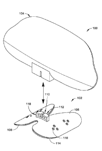
[0008] FIG. 1 is an exploded view of a lock-block shield device in accordance
with embodiments
of the present disclosure.
[0009] FIG. 2 is a cut-away view of a lock mechanism in accordance with
embodiments of the
present disclosure.
[0010] FIG. 3 is a partial cut-away view of a lock-block shield device with a
ball-and socket joint
that couples a shield and base in accordance with implementations of the
present disclosure.
2b
Date Recue/Date Received 2021-07-23
CA 02924718 2016-03-17
WO 2015/042419
PCT/US2014/056585
[0011] FIG. 3A is exploded view of a lock-block shield device with a malleable
stem
connection that couples a shield and base in accordance with implementations
of the
present disclosure.
[0012] 3B is exploded view of a lock-block shield device with a clasp-type
connection
that couples a shield and base in accordance with implementations of the
present
disclosure.
[0013] FIG. 4 is a flow diagram illustrating a method for reducing radiation
exposure in a
medical environment in accordance with example implementations of the present
disclosure.
DETAILED DESCRIPTION
Overview
[0014] Physicians and medical personnel sometimes tradeoff radiation
protection for
ergonomic and procedural efficiency during interventional procedures. Physical
barriers
used to block radiation typically are heavy due to the presence of lead. Some
physicians,
for example, do not use or sparingly use physical barriers for radiation
protection when
inserting catheters or drains because these barriers interfere with workflow
or cause
orthopedic stress when performing the procedure. As a result, the physician
may be
exposed to a higher cumulative level of radiation than is recommended on a
monthly
basis.
[0015] Another drawback of physical barriers is that reusable physical
barriers can act as
a conduit for spreading pathogens between people including patients and
medical
personnel. A contaminated physical barrier can transmit pathogens such as
multi-drug
resistant skin pathogen (MRSA) between people. It may be inefficient to clean
physical
barriers between uses.
[0016] Accordingly, a lock-block shield device is configured to at least
partially (e.g.,
partially, substantially, or completely) block potentially harmful radiation
(e.g., radiation
within a spectrum of wavelengths, such as x-ray radiation, that may be harmful
to the
human body when the human body is undesirably exposed to the radiation source)
is
3
CA 02924718 2016-03-17
WO 2015/042419
PCT/US2014/056585
described. In embodiments, the lock-block shield device is disposable or
suitable for
single use to avoid transmitting pathogens between patients.
[0017] In embodiments, the lock-block shield device includes a base and a
shield for
blocking radiation in medical situations. The base and shield are connected to
one
another by a clasp mechanism. The base is constructed to adhesively secure the
device to
an object, such as a patient or an object associated with the patient, and the
shield can be
positioned to block radiation. Thus, the lock-block shield device can be
arranged to
promote ergonomic activity and permit efficient work flow.
[0018] The shield and base, in embodiments, are coupled by a ball and socket
joint to
permit rotation of the shield with respect to the base. In examples, the
shield is
configured to articulate along an axis that is generally perpendicular to an
axis through
which the shield can be rotated. In additional examples, the shield and base
are coupled
by a fixating slot. Accordingly, the shield can be oriented and articulated to
readily
achieve a desired configuration that blocks radiation for a healthcare worker
while
minimizing procedural interference.
[0019] In embodiments, a lock-block shield device includes a lock mechanism,
such as a
clamp, for securing a work piece that is generally tubular, such as a
catheter, drain, or
other tube-like structure, to the base. In embodiments, the lock mechanism can
be
secured or released with and/or without removal of the shield. Thus, a user
such as a
physician or other health care worker can position or reposition a catheter
while the
shield is in place to block radiation directed to the physician.
Example Lock-Block Shield Devices
[0020] FIG. 1 illustrates an example lock-block shield device 100. The lock-
block shield
device 100 includes a base 102 and a shield 104. The base and shield, for
example, can be
provided as a single use kit that is assembled at a point of use and
subsequently disposed
of after a procedure to avoid cross-contamination. The shield and/or base can
be
provided in a variety of sizes, such as small, medium, or large with respect
to one
another.
4
CA 02924718 2016-03-17
WO 2015/042419
PCT/US2014/056585
[0021] The lock-block shield device 100 can be positioned on a patient, for
instance, so
that it is adjacent to the patient's liver when inserting a bile drain using
real-time x-ray
imaging. In this manner, the device 100 can shield (e.g., protect) the
healthcare worker's
hands from the x-ray radiation while allowing the healthcare worker to
position his/her
hands in an ergonomically effective manner that does not disrupt the worker's
workflow.
Protecting portions of a healthcare worker's body adjacent to a source of
radiation or an
area being imaged with x-rays can be beneficial as radiation exposure
decreases based on
the square of the distance between the radiated area and the object, e.g., a
physician's
hands. A physician's hands can be exposed to nine times the radiation to which
his/her
torso is exposed while using real-time x-ray imaging. In examples, the
radiation energy
is in the rage of and/or approximately 100 KeV.
[0022] The base 102 as shown includes a flap 106 that is butterfly shaped and
is formed
of a plastic suitable for medical applications. Although a flap with a
butterfly shape is
illustrated, the flap's shape can be varied based on design preference. As
illustrated, the
flap 106 has a substantially flat surface 108 that allows it to rest on an
object. The object
can be a patient or an object associated with a patient, e.g., a table, a
drape, or the like. In
embodiments, the flap 106 is curved or is malleable. For example, the flap 106
is
malleable to curve or bend to conform to a patient's torso.
[0023] The base 102 can be fabricated from a variety of materials. In
embodiments, the
base 102 is manufactured from a plastic. In further embodiments, the base
and/or flap is
formed from a wire or wire-type structure. For example, a metallic wire,
coated with a
medical grade plastic, may be shaped to form the flap, e.g., formed with a
butterfly shape
to function as a substantially flat surface on which the lock-block can rest.
In
implementations, the wire forming the base is malleable to conform to a curved
surface.
A variety of factors can be considered when selecting a plastic for the base
102. Factors
include, but are not limited to, resistance to microbe/bacterial
contamination, rigidity,
thermal stability, likelihood for triggering an allergic reaction, the
plastic's ability to be
infused with a radiation blocking material (e.g., accept powdered barium) and
the like.
CA 02924718 2016-03-17
WO 2015/042419
PCT/US2014/056585
[0024] As shown, the base 102 includes a protrusion 110 that extends generally
away
from the substantially flat surface 108. The protrusion 110 can be used to
support the
shield 104, to function as a stat lock, or for another purpose or combination
of purposes.
For example, the protrusion defines a slot 112 that is configured to receive a
tube shaped
work piece, e.g., a catheter, in order to secure it to the lock-block shield
device 100.
[0025] In embodiments, the base 102 and/or flap 106 may have a profile that is
ramped
so that a portion of the base that is to hold the work piece, e.g., a drain,
is spaced away
from an object on which the base is placed. For example, the base may ramp
from 3-5
millimeters to 6-10 millimeters. In embodiments, the protrusion is ramped. For
example,
the base 102 is substantially flat while the protrusion is ramped. Spacing the
work piece
away from the object can promote greater freedom of motion to adjust the work
piece.
The additional freedom may be attributed to the work piece being able to move
in x-y
directions with respect to the base. Thus, a healthcare worker may more easily
adjust a
hemostasis valve (an example work piece) by adjusting it in multiple
directions.
[0026] A foam base 114 is attached to the flat surface 108 of the base
illustrated in FIG.
1. The foam base 114 can be made of a suitable medical grade material. The
foam base is
coated with an adhesive material, e.g., a medical grade adhesive, on a side
opposite the
flap 106. The lock-block shield device 100 can be provided with a plastic or
foil sheet
that covers the adhesive and is removed to expose the layer of adhesive
material for use.
[0027] In embodiments, the foam base 114 is formed of a dense foam with a
thickness of
in the range of 1 millimeter to 2.5 centimeters. In embodiments, the foam has
a thickness
of approximately 1 millimeter. The foam can be selected to minimize fluids
from
absorbing in the foam's voids, user comfort, flexibility, suitability as a
substrate for the
adhesive, a combination of factors, and so forth.
[0028] The adhesive can be selected from a variety of medical grade adhesives
based on
a variety of factors. For example, the adhesive is selected for its ability to
adhere to a
patient's skin or to a drape, while still permitting it to release with
alcohol (e.g., ethyl
6
CA 02924718 2016-03-17
WO 2015/042419
PCT/US2014/056585
alcohol). The adhesive may be chosen to resist water, blood, or other bodily
fluids,
minimize the likelihood of an allergic reaction by a patient, and so forth.
[0029] As shown, the base 102 has one or more apertures 116 that extend
through the
flap 106 and/or the foam base 112. The apertures 116 are configured for use in
suturing
the base 102 to an object. A medical worker such as a physician, for instance,
can suture
the base 102 to a patient's skin through one or more of the apertures in
addition to adhere
the base to the patient's skin, such as for a patient with an allergy to an
adhesive. Other
suitable mechanism for securing the base 102 include, but are not limited to,
a suction
device, one or more straps (e.g., adjustable straps).
[0030] As shown in FIG. 1, the base 102 includes a lock mechanism 118 for
holding a
work piece that has a substantially tubular shape. The lock mechanism 118 can
be used
to secure a catheter, a drain, an intravenous line, or the like. For example,
the lock-block
shield device 100 is adhered adjacent to where a catheter exits a patient and
the lock
mechanism 118 holds the catheter to prevent it from coming loose from the
patient. In
embodiments, the lock mechanism is configured to secure catheter's in the
range of
between 4 French to 12 French. The lock mechanism can be configured for a
particular
size or may be configured for a range of sizes.
[0031] The lock mechanism 118 is at least partially housed in the protrusion
110. For
example, the lock mechanism is positioned adjacent to a slot in the protrusion
to hold a
drain that is positioned lengthwise in the slot. The lock mechanism 118, in
some
embodiments, can accommodate side arms that are included on some work pieces.
For
example, the lock mechanism can hold a hemostasis valve with side arms that
extend
from the valve's main body. In this example, the lock mechanism 118 and/or the
slot is
formed with a channel or recess into which the side arms are received. Having
described
features of the base generally, an embodiment of a lock mechanism is now
described.
[0032] Referring now to FIG. 2, an embodiment of lock mechanism 118 and its
operation
are further illustrated and described. As shown, the lock mechanism 118
includes one or
7
CA 02924718 2016-03-17
WO 2015/042419
PCT/US2014/056585
more clamps (two are shown, respectively, 220a and 220b) for securing a work
piece 221
to the base 102. Although clamp 220a is discussed, it is to be appreciated
that additional
clamps can be constructed and function in substantially the same manner. In
embodiments, the clamp 220a is shaped as a bar that extends along a side of a
slot in the
protrusion. In the illustrated embodiment, the clamp is biased to engage the
work piece
221. In embodiments, the clasp 118 functions to secure or further secure the
work piece
221, e.g., the clamps hold the work piece and the clamp pivots to secure the
work piece in
place like a hinged door. For example, the clamp 220a is biased perpendicular
to a tube's
primary axis to capture or release the tube as if the tube was held in the
stocks. In some
embodiments, foam that is sufficiently dense to retain the work piece may be
used, e.g.,
have a spring-type quality. The clamps 220a, 220b may be biased to engage the
work
piece 221 when not actuated, e.g., the clamp 220a is manipulated to release
the work
piece 221. In embodiments, a front face of the clamp toward the work piece
includes a
surface texture or is slightly curved (e.g., a concave surface) to assist in
holding the tube.
Other lock mechanisms can be used as well. Examples of other lock mechanisms
include, but are not limited to, a pivot lock or cam lock.
[0033] In embodiments, the lock mechanism 118 is configured to secure and/or
release
without removal of the shield 104. For example, the clamp 220a is pressed to
release or
disengage a catheter without dissembling the shield 104 from the base 102.
This
configuration permits a healthcare worker to adjust the catheter while keeping
the shield
104 in place to block radiation.
[0034] In implementations, a plug that blocks radiation is included with the
lock-block
shield device 100. The plug is configured to fit in the lock mechanism 118 and
block
radiation when no work piece is present. The plug may be used, for example,
when the
lock-block shield device 100 is used as a radiation shield for a barium
swallow. In this
example, the plug is inserted in the lock mechanism 118 to prevent radiation
from
passing through the slot.
[0035] Referring to FIGS. 3, 3A, and 3B, other lock-block shield device
features are now
8
CA 02924718 2016-03-17
WO 2015/042419
PCT/US2014/056585
described. As noted above, these features can be used individually or in
combination
with the features illustrated and described with respect to FIGS. 1 and 2.
[0036] As illustrated in FIG. 3, the lock block 300 includes a ball and socket
joint,
respectively 322 and 324. The ball and socket joint can be used to couple the
base 102
and shield 104 while permitting the shield/base to rotate and/or articulate
with respect to
the other component. Although the ball and/or socket can be formed from a
variety of
materials, in embodiments the ball is formed from a malleable metal or other
malleable
material that can be sized to fit in an aperture or recess formed in the base
or locking
mechanism. For example, the shield 104 is configured to rotate 360 about an
axis that is
generally perpendicular to the flap 106. The shield 104 can articulate with
respect to the
base 102 as well. For instance, the shield 104 can articulate along a second
axis that is
substantially perpendicular to that about which the rotation occurs.
Accordingly, the
shield 104 can tip forward and back along the second axis. .
[0037] The ball and socket joint can include one or more stops to limit the
extent to
which the shield/base can articulate. Stops can be included to limit the
shield from
articulating more than plus or minus 30'. Although a lock-block shield device
can
include a clasp and a ball and socket joint, in embodiments a ball and socket
can function
as a clasp. For example, the socket 324 is configured to snap-fit with a ball
shaped
structure 322 on the opposite component (e.g., the base or the shield) to
clasp the base
102 and shield 104 together. For example, a wire ball or wire socket can be
used to
connect with the clasp (e.g., door hinge structure or locking top with a hole
for a wire to
obtain a snug fit).
[0038] As illustrated in FIG. 3A, in an embodiment, a lock-block 301 includes
a
malleable stem 328 that couples the shield 104 to the base 102. The stem can
be
sufficiently malleable to allow it to at least partially deform when connected
to the
corresponding component. For example, the stem has a malleable end that fits
in an
aperture or recess 330 formed in one or more of the base, shield, or the
locking
mechanism. The stem 328 can be formed of a material that is sufficiently
malleable to
permit it to angle in multiple directions, such as to greater than 180 degrees
in 2 planes
9
CA 02924718 2016-03-17
WO 2015/042419
PCT/US2014/056585
and rotate 360 degrees with respect to the base or shield. In further
embodiments, at least
a portion of the stem 328 connects to a fixation slot formed adjacent to or in
an aperture
or recess in the base or base locking mechanism. Thus, for instance, an end
portion of the
stem is inserted in the slot and the door portion of a hinged clasp is closed
at least
partially about the end portion to secure it, e.g., hold it in a snug manner
so the stem is
capable of retaining a fixed position. Additionally, in embodiments
implementing a wire
base, the wire base can be configured to drop into the clasp as part of an
attachment
procedure.
[0039] As illustrated in FIG. 3B, the lock-block 303 includes a clasp that is
configured to
secure the base 102 and the shield 104 together. In embodiments, the clasp is
a hinged
clasp. For example, as can be seen in FIG. 3B the base 102 and the shield 104
are formed
with corresponding structures (e.g., a "c" shaped clasp 332 that engages a
cylindrical rod
334) that clasp the base and shield together. The clasp includes a securing
mechanism in
embodiments. Example securing mechanisms include a tab that is configured to
engage a
recess, a catch, or aperture on the opposing component, e.g., the base or the
shield. The
clasp can be configured to secure the shield and base without interfering with
operation
of the lock mechanism and/or operation of the shield.
[0040] Referring now to FIG. 3, construction and operation of a shield 104 in
accordance
with embodiments of the present disclosure are now described. The shield 104
can be
formed of one or more layers of material that are designed to block the
transmission of
radiation through the shield 104. For example, the shield is composed of a
sheet of a
radiation blocking material, such as a lead foil 326, sandwiched between
plastic layers. In
embodiments, the shield offers radiation shielding equivalent to a lead layer.
[0041] Other suitable radiation blocking materials can be used as well
including, but not
limited to, tin or aluminum. In other embodiments, the plastic forming the
shield can be
infused with radiation blocking material, such as barium sulfate, a metal
infused polymer
(e.g., tantalum), that is mixed in the plastic. For example, the shield is
formed of a plastic
loaded with barium sulfate and/or tungsten. Barium sulfate may be selected
because its
weight is approximately two thirds or sixty-six percent (66%) that of lead.
For example,
CA 02924718 2016-03-17
WO 2015/042419
PCT/US2014/056585
a five by eight inch (5"x 8") sheet of barium sulfate and/or tungsten loaded
plastic can
weigh approximately one quarter of a pound (0.25 lbs).
[0042] As shown, the shield 104 includes a lip 328 that extends about at least
a portion of
the shield's periphery. For instance, the shield 104 includes an extension or
is curved,
e.g., is concave, to prevent liquids such as blood and other bodily fluids
from contacting a
healthcare worker. For example, the lip 328 extends from a major surface of
the shield.
The shield 104 can be positioned so the lip 328 is directed to, for example, a
physician to
prevent blood from splashing on a physician's hands positioned on an opposite
side of the
shield 104.
[0043] The shield, in accordance with embodiments of the present disclosure,
is
adjustable to expand or contract to vary the extent to which the shield blocks
radiation.
For example, the shield 104 can be formed in multiple sections that fan out
like a deck of
playing cards or a paper fan. In this example, the shield 104 is composed of
multiple
sections that can slide or pivot past one another to expand or contract the
area blocked by
the shield.
[0044] In other embodiments, a shield 104 may include a central section from
which one
or more wing sections pivot or slide out of or into. Accordingly, a user can
pivot or slide
the wings to/from the central section to adjust the extent to which the shield
extends, e.g.,
a half circle or a three quarter circle. It is to be apparent that the
structures, techniques,
and approaches described with respect to FIGS. 1-3B may be implemented in
conjunction
with the methods described below.
Example Methods
[0045] The following discussion describes methods that may be implemented in
conjunction with a lock-block shield device described above. The methods are
shown as
a set of blocks that specify operations and are not necessarily limited to the
order shown.
In portions of the following discussion, reference may be made to the lock-
block shield
device 100 and/or its components. The techniques described below are
independent of
11
CA 02924718 2016-03-17
WO 2015/042419
PCT/US2014/056585
the structures described above, meaning that the techniques may be implemented
in a
variety of ways and are not necessarily limited to the structures illustrated
in FIGS. 1-3.
[0046] FIG. 4 depicts a method 400 in an example implementation for blocking
radiation
in a medical environment. The method may be used to block radiation from
contacting a
healthcare worker assisting a patient during a procedure in which the patient
is exposed to
at least some radiation.
[0047] As illustrated, a base is secured to an object (Block 402). The base
may be
secured to the object with an adhesive and/or a suture. The object in
implementations is a
patient or an object associated with a patient, such as a gown, a drape, or a
table. For
example, the base is sutured to the patient's gown to prevent it from coming
loose.
[0048] A shield is attached with the base (Block 404). For example, the shield
is
snapped to the base using opposing structures included, respectively, on the
base and
shield. In embodiments, the shield attaches in a hinged manner and is secured
in place by
a friction tab that locks the opposing structures together. In other
embodiments, a snap fit
ball and socket joint is used to couple the base and shield together. For
example, a ball
may be press-fit into a socket formed by two or more fingers.
[0049] A shield is deployed (Block 406). The shield can be deployed depending
on the
situation to configure the shield to block radiation from contacting a
healthcare worker
treating a patient who is being exposed to at least some radiation. For
example, the shield
can be adjusted in a variety of ways based on the patient's position, the
location of the
radiation source, the healthcare worker's position, and so forth.
[0050] Optionally, a shield is rotated to orientate the shield (Block 408).
For example,
with the base secured, the shield is rotated to align the shield and prevent a
physician's
hands being exposed to radiation from an x-ray machine. The shield can be
rotated 360
so the base can be placed in a manner that does not interfere with workflows
and allow
for ergonomic placement.
[0051] Optionally, a shield is articulated (Block 410). The shield can be
articulated with
12
CA 02924718 2016-03-17
WO 2015/042419
PCT/US2014/056585
respect to the base. For example, the shield 104 articulates +1- 300 so it can
be angled for
a variety of factors. Example factors include, but are not limited to, the
height and
orientation of the patient, an x-ray source position, the position of the lock
block shield
device with respect to an area of interest, or a position of the physician or
healthcare
worker with respect to the lock-block shield device.
[0052] Optionally, the shield is adjusted to vary the extent to which the
shield blocks
radiation (Block 412). For example, the shield 104 can be adjusted to fan out
in order to
shield more area. Alternatively, the shield can be pivoted to contract the
area that is
shielded, e.g., by folding the shield's segments together. The shield, for
instance, may
extend approximately 180 when positioned on a table, but may fan-out to cover
an angle
of 225 when positioned on a patient's torso. In embodiments, segments forming
the
shield can pivot or slide past one another to expand to cover a greater
portion or fold-up
to decrease the shield's angular coverage orientation.
[0053] In embodiments, a lock mechanism is secured or released without removal
of the
shield (Block 414). For example, a lock mechanism 118 for securing a bile
drain can be
released without removing the shield 104 from the base 102 to which it is
attached.
[0054] In embodiments, the shield is disposed of after a single use (Block
416). For
example, the lock-block shield device including the shield is disposable to
prevent
pathogens from transferring between people such as patient and healthcare
workers
between uses. In additional embodiments, device or one of its components can
be
constructed so it can be sterilized for reuse.
Conclusion
[0055] Although the subject matter has been described in language specific to
structural
features and/or process operations, it is to be understood that the subject
matter defined in
the appended claims is not necessarily limited to the specific features or
acts described
above. Rather, the specific features and acts described above are disclosed as
example
forms of implementing the claims.
13