Note: Descriptions are shown in the official language in which they were submitted.
CA 02925372 2016-03-24
WO 2015/043873
PCT/EP2014/068344
1
DESCRIPTION
TITLE
HARQ-ACK Resource Allocation and Use for elMTA
TECHNICAL FIELD
[0001] This invention relates generally to Hybrid Automatic Repeat reQuest
(HARQ) resource allocation and, more specifically, relates to HARQ resource
allocation
for Enhanced Interference Management and Traffic Adaptation (eIMTA).
BACKGROUND
[0002] This section is intended to provide a background or context to the
invention
disclosed below. The description herein may include concepts that could be
pursued, but
are not necessarily ones that have been previously conceived, implemented or
described.
Therefore, unless otherwise explicitly indicated herein, what is described in
this section is
not prior art to the description in this application and is not admitted to be
prior art by
inclusion in this section. Abbreviations that may be found in the
specification and/or the
drawing figures are defined at the end of this document, prior to the claims.
[0003] 3GPP LTE Rel-12 will be part of an LTE-Advanced system. The instant
disclosure focuses on PUCCH resource allocation for HARQ-ACK related to
dynamic UL-
DL reconfiguration for TD-LTE (or TDD mode of LTE). As is known, HARQ-ACK is a
technique for sending error information indicating received information was
not correctly
received. The description herein falls within the scope of Rel-12 Work Item
elMTA ¨
"Further Enhancements to LTE TDD for DL-UL Interference Management and Traffic
Adaptation". The Work Item Description for elMTA (RP-121772 by CATT) was
approved
at RAN#58 meeting, Barcelona, Spain, December 4th ¨ 7th, 2012.
[0004] The goal of the elMTA WI is to enable more flexible TDD UL-DL
reconfiguration for traffic adaptation in, e.g., small cells. The starting
point following the
Rel-12 assumptions is that the eNodeB may vary UL-DL configuration relatively
often
(e.g., for those UEs configured to a flexible UUDL mode) compared to the
existing
situation where UL-DL configuration is in practice very stationary. For
instance, TD-LTE
Rel-11 supports UL-DL reconfiguration with periodicity of 640 ms or longer.
The basic
assumptions for elMTA functionality, based on RAN WG1 progress, are listed
below:
= There is a predefined cell-specific UL-DL configuration broadcasted
in the cell using SIB-1. The legacy UEs (Re1-8 to Rel-11) in the cell follow
this
configuration all the time.
CA 02925372 2016-03-24
WO 2015/043873
PCT/EP2014/068344
2
= No new TDD UL-DL configurations are introduced: Flexible TDD
reconfiguration can only happen among existing (e.g., seven) configurations.
These
configurations are described in more detail below.
= TDD reconfiguration can occur with (at most) radio frame (=10 ms)
periodicity for those UEs configured to the new flexible configurations.
= In each UL-DL configuration, there are fixed subframes where the
link direction is always predetermined. These fixed subframes are denoted as D
(Downlink), S (Special) and U (Uplink).
= Additionally, there are as well flexible subframes (denoted as F).
Flexible subframes can be used as D or U. From the measurement point of view
of legacy
UEs, it may be possible to use a special subframe (e.g., subframe #6 of the
radio frame)
only as S or D (but not U).
= The number of flexible subframes depends on the scenario (such as
SIB-1 configuration and DL reference configuration defining HARQ/scheduling
timing for
PDSCH).
[0005] Regarding the existing TDD UL-DL configurations, FIG. 1 illustrates
UUDL
configurations for TD-LTE (Re1-8/9/10/11). Physical PUSCH resources are
located
between two PUCCH segments shown in FIG. 2. Mapping of logical PUCCH resource
blocks, denoted as m, into physical PUCCH resource blocks is also shown in
FIG. 2.
Taking into account the logical split between different PUCCH Formats, it is
noted that
PUCCH Format 2/2a/2b carrying periodic CSI reports is located at the outermost
resource
blocks (either near RBO or near NRBuL ¨1) of the system bandwidth. ACK/NACKs
for
persistently scheduled PDSCH and SRIs are located on the PUCCH resource blocks
next
to periodic CSI while the ACK/NACK resources reserved to dynamically scheduled
PDSCH are located at the innermost resource blocks reserved for PUCCH. It can
be
noted that the size of dynamic PUCCH defines the continuous spectrum available
for
PUSCH. That is, the area between the areas for PUCCH may be used for PUSCH.
[0006] Turning to FIG. 3, this figure is an example of a radio frame with 10
subframes showing Downlink (D), Uplink (U) and Special (S) subframes according
to
exemplary SIB-1 configured UL-DL configuration #0, as well as flexible
subframes
available for Rel-12 UEs configured to flexible UUDL mode. TDD configuration 0
(zero) is
used in FIG. 3, but the same principle applies to other configurations as
well. In addition to
the SIB-1 configured UL-DL configuration, which defines whether a given
subframe in the
radio frame is downlink, special, or uplink subframe, in the case of flexible
TDD UL-DL
configurations, e.g., some of the uplink subframes can be changed from what is
shown in
CA 02925372 2016-03-24
WO 2015/043873
PCT/EP2014/068344
3
the row labeled "SIB-1" into downlink subframes (as can a special subframe be
changed
into a downlink subframe).
[0007] In TDD elMTA systems, HARQ/scheduling timing related issues are still
under active discussions although basic principles have been agreed upon. The
remaining
open questions in RAN WG1 relate, e.g., to exact HARQ timeline, HARQ process
continuity, HARQ-ACK resource allocation, and the like.
[0008] In this disclosure, the focus is placed on the HARQ-ACK resource
allocation on PUCCH. In the current specifications (up to Rel-11), the PUCCH
HARQ-
ACK resources are implicitly determined based on the lowest (i.e., first) CCE
of the
corresponding PDCCH and semi-statically configured PUCCH Format 1/la/lb
starting
position. Furthermore, in TDD mode, there is a separate timing offset defined
as a function
of SIB-1 configuration and the subframe index. From HARQ/timing point of view,
the
elMTA feature will create two parallel sets of UEs sharing the same PUCCH
Format
1/1a/1b resources:
[0009] = Legacy UEs following HARQ/scheduling timing according to SIB-1
UL-DL configuration; and
[0010] = elMTA UEs following HARQ/scheduling timing according to
DL
reference configuration.
[0011] This will create PUCCH resource collision problems, which should be
avoided by proper system design. Otherwise, additional complexity is involved
in the
scheduler entity allocating shared PDCCH (and/or EPDCCH) resources between
legacy
UEs and elMTA UEs.
BRIEF SUMMARY
[0012] The following is meant to include examples of possible embodiments and
is
not meant to be limiting.
[0013] An exemplary embodiment is a method comprising: receiving a downlink
data transmission in a downlink subframe; determining one or more resources to
be used
for transmission of error information for the received transmission in an
uplink subframe
based at least on an association set between one or more downlink or special
subframes
and an uplink subframe, wherein the determined association set depends on a
downlink
reference configuration, wherein the association set for each uplink subframe
comprises a
grouping of the downlink or special subframes into at least two groups, and
wherein an
association set is defined only for the subframes which are uplink subframes
in a
corresponding downlink reference configuration; and transmitting the error
information
using the determined one or more resources in the uplink subframe.
CA 02925372 2016-03-24
WO 2015/043873
PCT/EP2014/068344
4
[0014] An additional exemplary embodiment includes a computer program,
comprising code for performing the method of the previous paragraph, when the
computer
program is run on a processor. The computer program according to this
paragraph,
wherein the computer program is a computer program product comprising a
computer-
readable medium bearing computer program code embodied therein for use with a
computer.
[0015] An exemplary apparatus includes one or more processors and one or more
memories including computer program code. The one or more memories and the
computer program code are configured to, with the one or more processors,
cause the
apparatus to perform at least the following: receiving a downlink data
transmission in a
downlink subframe; determining one or more resources to be used for
transmission of
error information for the received transmission in an uplink subframe based at
least on an
association set between one or more downlink or special subframes and an
uplink
subframe, wherein the determined association set depends on a downlink
reference
configuration, wherein the association set for each uplink subframe comprises
a grouping
of the downlink or special subframes into at least two groups, and wherein an
association
set is defined only for the subframes which are uplink subframes in a
corresponding
downlink reference configuration; and transmitting the error information using
the
determined one or more resources in the uplink subframe.
[0016] A further exemplary embodiment is an apparatus comprising: means for
receiving a downlink data transmission in a downlink subframe; means for
determining
one or more resources to be used for transmission of error information for the
received
transmission in an uplink subframe based at least on an association set
between one or
more downlink or special subframes and an uplink subframe, wherein the
determined
association set depends on a downlink reference configuration, wherein the
association
set for each uplink subframe comprises a grouping of the downlink or special
subframes
into at least two groups, and wherein an association set is defined only for
the subframes
which are uplink subframes in a corresponding downlink reference
configuration; and
means for transmitting the error information using the determined one or more
resources
in the uplink subframe.
[0017] Another exemplary embodiment is a method comprising: transmitting a
downlink data transmission in a downlink subframe; determining one or more
resources to
be used for reception of error information for the received transmission in an
uplink
subframe based at least on an association set between one or more downlink or
special
subframes and an uplink subframe, wherein the determined association set
depends on a
downlink reference configuration, wherein the association set for each uplink
subframe
CA 02925372 2016-03-24
WO 2015/043873
PCT/EP2014/068344
comprises a grouping of the downlink or special subframes into at least two
groups, and
wherein an association set is defined only for the subframes which are uplink
subframes in
a corresponding downlink reference configuration; and receiving error
information using
the determined one or more resources in the uplink subframe.
5 [0018] An additional exemplary embodiment includes a computer program,
comprising code for performing the method of the previous paragraph, when the
computer
program is run on a processor. The computer program according to this
paragraph,
wherein the computer program is a computer program product comprising a
computer-
readable medium bearing computer program code embodied therein for use with a
computer.
[0019] An exemplary apparatus includes one or more processors and one or more
memories including computer program code. The one or more memories and the
computer program code are configured to, with the one or more processors,
cause the
apparatus to perform at least the following: transmitting a downlink data
transmission in a
downlink subframe; determining one or more resources to be used for reception
of error
information for the received transmission in an uplink subframe based at least
on an
association set between one or more downlink or special subframes and an
uplink
subframe, wherein the determined association set depends on a downlink
reference
configuration, wherein the association set for each uplink subframe comprises
a grouping
of the downlink or special subframes into at least two groups, and wherein an
association
set is defined only for the subframes which are uplink subframes in a
corresponding
downlink reference configuration; and receiving error information using the
determined
one or more resources in the uplink subframe.
[0020] An additional exemplary embodiment is an apparatus comprising: means
for transmitting a downlink data transmission in a downlink subframe; means
for
determining one or more resources to be used for reception of error
information for the
received transmission in an uplink subframe based at least on an association
set between
one or more downlink or special subframes and an uplink subframe, wherein the
determined association set depends on a downlink reference configuration,
wherein the
association set for each uplink subframe comprises a grouping of the downlink
or special
subframes into at least two groups, and wherein an association set is defined
only for the
subframes which are uplink subframes in a corresponding downlink reference
configuration; and means for receiving error information using the determined
one or more
resources in the uplink subframe.
CA 02925372 2016-03-24
WO 2015/043873
PCT/EP2014/068344
6
BRIEF DESCRIPTION OF THE DRAWINGS
[0021] In the attached Drawing Figures:
[0022] FIG. 1 illustrates UUDL configurations for TD-LTE (Re1-8/9/10/11);
[0023] FIG. 2 illustrates mapping of logical PUCCH RBs into physical RBs;
[0024] FIG. 3 is an example of a radio frame with 10 subframes showing
Downlink
(D), Uplink (U) and Special (S) subframes according to exemplary SIB-1
configuration #0,
as well as Flexible (F) subframes available for Rel-12 UEs configured to
flexible UUDL
mode;
[0025] FIG. 4 is a block diagram of an exemplary system in which the exemplary
embodiments may be practiced;
[0026] FIG. 5 illustrates a table for downlink association set index K:
{ko,ki,===km_i} for TDD and is a copy of Table 10.1.3.1-1 from 3GPP TS 36.213
V11.3.0
(2013-06);
[0027] FIG. 6 illustrates PUCCH resource collisions in elMTA and is Figure 1
from
MediaTek Inc., "Discussion on HARQ-ACK resource in TDD elMTA", R1-133282, 3GPP
TSG-RAN WG1 Meeting #74, Barcelona, Spain, 19th ¨ 23rd August 2013;
[0028] FIG. 7 illustrates an elMTA PUCCH HARQ-ACK resource grouping
according to an exemplary embodiment;
[0029] FIG. 8 illustrates grouping to DL / special subframes according to an
exemplary embodiment;
[0030] FIG. 9 illustrates a downlink association set index K : fko,ki,===km_il
for
TDD, DL reference configuration = 5;
[0031] FIG. 10 illustrates a downlink association set index K: fko,ki,===km_il
for
TDD, DL reference configuration = 2;
[0032] FIG. 11 is a logic flow diagram performed by a UE for HARQ-ACK resource
allocation and use for elMTA, which uses legacy and elMTA tables of downlink
association set indexes, and illustrates the operation of an exemplary method,
a result of
execution of computer program instructions embodied on a computer readable
memory,
and/or functions performed by logic implemented in hardware, in accordance
with an
exemplary embodiment;
[0033] FIG. 12 is a logic flow diagram performed by an eNB for HARQ-ACK
resource allocation and use for elMTA, which uses legacy and elMTA tables of
downlink
association set indexes, and illustrates the operation of an exemplary method,
a result of
execution of computer program instructions embodied on a computer readable
memory,
CA 02925372 2016-03-24
WO 2015/043873
PCT/EP2014/068344
7
and/or functions performed by logic implemented in hardware, in accordance
with an
exemplary embodiment;
[0034] FIG. 13 is a logic flow diagram performed by a UE for HARQ-ACK resource
allocation and use for elMTA, which uses only elMTA tables of downlink
association set
indexes, and illustrates the operation of an exemplary method, a result of
execution of
computer program instructions embodied on a computer readable memory, and/or
functions performed by logic implemented in hardware, in accordance with an
exemplary
embodiment;
[0035] FIG. 14 is a logic flow diagram performed by an eNB for HARQ-ACK
resource allocation and use for elMTA, which uses only elMTA tables of
downlink
association set indexes, and illustrates the operation of an exemplary method,
a result of
execution of computer program instructions embodied on a computer readable
memory,
and/or functions performed by logic implemented in hardware, in accordance
with an
exemplary embodiment;
[0036] FIG. 15 is a logic flow diagram performed by a UE for HARQ-ACK resource
allocation and use for elMTA, and illustrates the operation of an exemplary
method, a
result of execution of computer program instructions embodied on a computer
readable
memory, and/or functions performed by logic implemented in hardware, in
accordance
with an exemplary embodiment;
[0037] FIG. 16 is a logic flow diagram performed by an eNB for HARQ-ACK
resource allocation and use for elMTA, and illustrates the operation of an
exemplary
method, a result of execution of computer program instructions embodied on a
computer
readable memory, and/or functions performed by logic implemented in hardware,
in
accordance with an exemplary embodiment;
[0038] FIG. 17 is a subframe indexing table for subframes for which elMTA and
non-eIMTA UEs have the same timing (Group 1 subframes); and
[0039] FIG. 18 is a subframe indexing table for subframes for which elMTA and
non-eIMTA UEs have the different timing (Groups 2 and 3 subframes).
DETAILED DESCRIPTION OF THE DRAWINGS
[0040] The exemplary embodiments herein describe HARQ-ACK resource on
PUCCH allocation for elMTA. Additional description of these techniques is
presented
after a system into which the exemplary embodiments may be used is described.
[0041] Turning to FIG. 4, this figure shows a block diagram of an exemplary
system in which the exemplary embodiments may be practiced. In FIG. 4, a
legacy UE
110-1 and an elMTA UE 110-2 are in wireless communication with a network 100.
Each
CA 02925372 2016-03-24
WO 2015/043873
PCT/EP2014/068344
8
of the user equipment 110 includes one or more processors 120, one or more
memories
125, and one or more transceivers 130 (comprising one or more transmitters,
Tx, and one
or more receivers, Rx) interconnected through one or more buses 127. The one
or more
transceivers 130 are connected to one or more antennas 128. The one or more
memories
125 include computer program code 123. The legacy UE 110-1 communicates with
eNB
175 via wireless link 111-1, and the elMTA UE 110-2 similarly communicates
with eNB
175 via wireless link 111-2. The elMTA UE 110-2 includes a HARQ-ACK RA
(Resource
Allocation) unit 121, which causes the elMTA UE 110-2 to perform the
operations
described herein. In an exemplary embodiment, the one or more memories 125-2
and the
computer program code 123-2 are configured, with the one or more processors
120-2, to
cause the user equipment 110-2 to perform one or more of the operations as
described
herein. The computer program code 123 can be code that forms the HARQ-ACK RA
unit
121. In another example, the HARQ-ACK RA unit 121 is formed at least in part
as
circuitry, e.g., in the one or more processors 120-2. As described in more
detail below,
the exemplary embodiments herein concern possible resource collisions between
the UEs
110-1 and 110-2 while using UL communications on the wireless links 111.
[0042] The eNB 175 includes one or more processors 150, one or more memories
155, one or more network interfaces (N/VV I/F(s)) 161, and one or more
transceivers 160
(comprising one or more transmitters, Tx, and one or more receivers, Rx)
interconnected
through one or more buses 157. The one or more transceivers 160 are connected
to one
or more antennas 158. The one or more memories 155 include computer program
code
153. The eNB 175 further includes a HARQ-ACK RA unit 151 that causes the eNB
175 to
perform operations as described herein. In an exemplary embodiment, the one or
more
memories 155 and the computer program code 153 are configured to, with the one
or
more processors 150, cause the eNB 175 to perform one or more of the
operations as
described herein. For instance, the HARQ ¨ACK RA unit 151 is implemented
(e.g., at
least in part) as the computer program code 153. In another example, the HARQ-
ACK RA
unit 151 is formed at least in part as circuitry, e.g., in the one or more
processors 150.
The one or more network interfaces 161 communicate over a network such as the
networks 170 and 131. Two or more eNBs 175 communicate using, e.g., network
170.
The network 170 may be wired or wireless or both and may implement, e.g., an
X2
interface.
[0043] The wireless network 100 may include a network control element (NCE)
190 that may include MME/SGW functionality, and which provides connectivity
with a
further network, such as a telephone network and/or a data communications
network (e.g.,
the Internet). The eNB 175 is coupled via a network 131 to the NCE 175. The
network
CA 02925372 2016-03-24
WO 2015/043873
PCT/EP2014/068344
9
131 may be implemented as, e.g., an Si interface. The NCE 190 includes one or
more
processors 177, one or more memories 171, and one or more network interfaces
(N/VV
I/F(s)) 180, interconnected through one or more buses 185. The one or more
memories
171 include computer program code 173. The one or more memories 171 and the
computer program code 173 are configured to, with the one or more processors
175,
cause the NCE 190 to perform one or more operations.
[0044] The computer readable memories 125, 155, and 171 may be of any type
suitable to the local technical environment and may be implemented using any
suitable
data storage technology, such as semiconductor based memory devices, flash
memory,
magnetic memory devices and systems, optical memory devices and systems, fixed
memory and removable memory. The processors 120, 150, and 177 may be of any
type
suitable to the local technical environment, and may include one or more of
general
purpose computers, special purpose computers, microprocessors, digital signal
processors (DSPs) and processors based on a multi-core processor architecture,
integrated circuits (e.g., designed to carry out one or more of the operations
herein), and
programmable modules such as field-programmable gate arrays (e.g.õ designed to
carry
out one or more of the operations herein), as non-limiting examples. Thus, the
exemplary
embodiments herein may be performed by the one or more memories 125 and the
computer program code 123 being configured, with the one or more processors
120, to
cause the UE to perform the operations herein, may be performed by hardware
(e.g.,
embodied in the one or more processors 120) such as integrated circuits and/or
programmable modules, or by some combination of these.
[0045] In general, the various embodiments of the user equipment 110 can
include, but are not limited to, cellular telephones such as smart phones,
personal digital
assistants (PDAs) having wireless communication capabilities, portable
computers having
wireless communication capabilities, image capture devices such as digital
cameras
having wireless communication capabilities, gaming devices having wireless
communication capabilities, music storage and playback appliances having
wireless
communication capabilities, Internet appliances permitting wireless Internet
access and
browsing, tablets with wireless communication capabilities, as well as
portable units or
terminals that incorporate combinations of such functions.
[0046] The exemplary embodiments herein concern HARQ-ACK resource
allocation on PUCCH for elMTA. Additional description of problems with
conventional
systems is first presented, and then exemplary embodiments are presented.
[0047] According to the agreements in RAN1#74, the TDD elMTA HARQ-ACK
feedback timing will most probably be based on a so-called reference
configuration
CA 02925372 2016-03-24
WO 2015/043873
PCT/EP2014/068344
principle (see NSN, Nokia, "On HARQ timing for TDD elMTA", R1-133477, 3GPP TSG-
RAN WG1 Meeting #74, Barcelona, Spain, 19 - 23 August 2013):
1) An UL reference UL/DL configuration defining:
a) PUSCH-to-PHICH timing;
5 b) DCl/PHICH-to-PUSCH timing; and
c) The number of HARQ processes for UL; and
2) A DL reference UUDL configuration (referred to as a "DL reference
configuration" herein) defining:
a) PDSCH-to-ACK timing;
10 b) The maximum number of HARQ processes for the DL side; and
c) HARQ-ACK signaling in UL (e.g., size of the HARQ-ACK
codebook).
[0048] The most probable solution is that UL reference configuration is
defined as
the UL-DL configuration signaled via by SIB-1. This simplifies the resource
allocation
especially in the (e.g., typical) case, when there exist legacy (Rel-11 and
earlier) UEs in
the cell that are not able to support dynamic UL-DL reconfiguration.
[0049] In the current specifications (up to Rel-11), the PUCCH HARQ-ACK
resource is implicitly determined from the corresponding physical resource
indices. For
example, the first CCE/ECCE index of PDCCH/EPDCCH is used to determine the DL
HARQ-ACK resource, along with index of the DL subframe and the index of the
OFDM
symbol carrying the CCE/ECCE and some higher-layer-configured parameters.
[0050] The specific issue in PUCCH format 1a/1b resource allocation for HARQ-
ACKs in TDD is that more than one DL subframe may be associated with a single
UL
subframe. As shown in the table shown in FIG. 5, the HARQ-ACKs corresponding
to M
(could be 1, 2, 3, 4) DL subframes are reported in one UL subframe. It is
noted that this
table is a copy of Table 10.1.3.1-1 from 3GPP TS 36.213 V11.3.0 (2013-06).
Furthermore, for the table shown in FIG. 5, the UE shall use PUCCH resource in
subframe
n, where PDSCH transmission is indicated by the detection of corresponding
PDCCH or
PDCCH indicating downlink SPS release within subframe(s) n¨k, where ke K. That
is,
for UL-DL configuration 0 (zero), the UE would report HARQ-ACKs in subframes
2, 4, 7,
and 9 for corresponding subframe offset values of 6, 4, 6, and 4.
[0051] When considering HARQ-ACK resource allocation for PUCCH, it is good to
understand in more detail the concept of the downlink association set depicted
in the table
of FIG. 5. The DL association set defines for each UL subframe n the timing
and the order
in which the HARQ feedback for each DUspecial subframe is transmitted. For
example,
with UL-DL configuration #0, in UL subframe #n=2 the PUCCH may carry the HARQ-
ACK
CA 02925372 2016-03-24
WO 2015/043873
PCT/EP2014/068344
11
for the DL subframe that was six subframes earlier, i.e., the HARQ delay in
this case is six
subframes. The table values for the HARQ delay are called the subframe offset
values
herein. Similarly, for UL-DL configuration 1 (one), in UL subframe #2 the HARQ-
ACK may
be signaled for DL subframes that were seven and/or six subframes earlier, and
the
PUCCH resources are filled in this specific order (e.g., first HARQ-ACK for DL
subframe
n-7, then for DL subframe n-6).
[0052] For PDCCH in Re1-8/9/10/11 TDD operation, PUCCH resources
corresponding to multiple DL subframes are concatenated and interleaved in the
associated UL subframe (e.g., with 40 CCEs per DL subframe and M=2, 80 PUCCH
resources are reserved), so that there are no resource collisions between
different
subframes. To be specific, the PDCCH resources corresponding to PDCCH OFDM
symbols [s1, s2, s3,...] and subframes [SF1, SF2, SF3, ..] are mapped to PUCCH
in the
following order:
= SF1-s1
= SF2-s1
= SF3-s1
. ...
= SF1-s2
= 5F2-s2
= 5F3-s2
. ...
[0053] Since the rule governing the implicit mapping depends on the UL-DL
configuration (according to the table shown in FIG. 5), it is likely that the
understandings of
the mapping between the physical resource index and HARQ-ACK resource between
elMTA and legacy UEs are different. In this case, the HARQ-ACK resources taken
by
elMTA and legacy UEs may collide as shown in FIG. 6. FIG. 6 illustrates PUCCH
resource collisions in elMTA and is Figure 1 from MediaTek Inc., "Discussion
on HARQ-
ACK resource in TDD elMTA", R1-133282, 3GPP TSG-RAN WG1 Meeting #74,
Barcelona, Spain, 19th ¨ 23rd August 2013. R1-133282 states the following
about this
figure (where "Figure 1" in the following is FIG. 6 herein): "For PUCCH format
1a/1b/1b
with channel selection, the DL HARQ-ACK (i.e., PUCCH) resource is implicitly
determined
by the first CCE/ECCE index used for the transmission of the corresponding
PDCCH/EPDCCH. One example is illustrated in Figure 1, in which it is assumed
the DL
HARQ reference configuration is 5, and the SIB-1 indicated configuration is 0.
An elMTA
UE receives a PDSCH in DL subframe #9, and a legacy UE receives in DL subframe
#6. If
CA 02925372 2016-03-24
WO 2015/043873
PCT/EP2014/068344
12
the first CCE/ECCE indices used for the transmissions of the PDCCH/EPDCCHs are
the
same, then DL HARQ-ACK resource collision happens in UL subframe #2."
[0054] The reason for the collision is as follows. Since the legacy UE 110-1
is
using configuration 0 (zero), according to the table in FIG. 5, the legacy UE
110-1 would
use e.g. subframe 2 for HARQ-ACK feedback and the PUCCH in subframe 2 would
carry
the HARQ-ACK for the DL subframe that was 6 subframes earlier. Meanwhile, the
elMTA
UE 110-2 would also use subframe 2 for HARQ-ACK feedback, since the elMTA UE
110-
2 uses configuration 5, and according to the table in FIG. 5, the elMTA UE 110-
2 would
use subframe 2 and the PUCCH would carry the HARQ-ACK for the DL subframes
that
were 13, 12, 9, 8, 7, 5, 4, 11, and/or 6 subframes earlier. elMTA UEs 110-2
use subframe
2 to transmit HARQ-ACK feedback corresponding to 9 subframes, with 9 different
offset
values (subframe with offset = 13 is placed first in the PUCCH). Thus, a
potential collision
occurs in subframe 2, since both legacy UE 110-1 and elMTA UE 110-2 are using
the
same resource (as implicitly determined by the first CCE/ECCE index) in
subframe 2.
[0055] In R1-133282, the basic problems related to PUCCH HARQ-ACK resource
allocation for elMTA are discussed and three main alternatives are suggested.
One
alternative is implicit resource allocation. The main drawback of this
alternative is that the
alternative keeps the PUCCH overhead constantly high. For instance, PUCCH
Format
1/1a/1b overhead can be as high as 40% (80*9 PRBs/18 =40 PRBs out of 100 PRBs)
when using 20 MHz BW, 3 OFDMA symbols for PDCCH and using typical PUCCH Format
1/1a/1b resource density (18 resources for HARQ-ACK per PRB which corresponds
to
delta shift=2; the delta shift is described in more detail below). In most
cases, PUCCH
Format 1/1a/1b overhead is always at maximum based on usage of a DL-heavy
configuration as DL reference configuration. This means that UL capacity may
become the
bottleneck for elMTA, which may mean that full potential of dynamic UL-DL
traffic
adaptation cannot be obtained.
[0056] A second alternative proposed in R1-133282 is explicit resource
allocation.
The problem with this option is that this alternative is fairly static: it is
not possible to adjust
the PUCCH resource dynamically and in order to avoid collisions, dedicated
resource will
in practice be needed for all UEs, increasing the PUCCH overhead
significantly.
[0057] A third alternative proposed in R1-133282 is partially implicit and
partially
explicit resource allocation: This is basically a combination of alternatives
one and two.
The main problem with this third alternative is that it easily leads to a very
complex
solution.
[0058] In the following description, solutions are discussed for avoiding HARQ-
ACK resource collisions on PUCCH. An exemplary aspect herein is to provide an
implicit
CA 02925372 2016-03-24
WO 2015/043873
PCT/EP2014/068344
13
mapping rule for the HARQ-ACKs corresponding to different types of DL
subframes in
elMTA (namely fixed and flexible). In other words, a new downlink association
set index
table is defined that is similar to the table shown in FIG. 5 for UEs
configured to the elMTA
mode. Rel-12 UEs should follow a new table when configured to elMTA & PUCCH
Format 1/1a/lb feedback mode (that is, instead of following the existing
table).
[0059] The problem is how to arrange DL association set indices defined by DL
reference configuration (e.g., UL-DL Configuration 5) in the case of elMTA.
For example,
in the case when DL reference configuration corresponds to #5, one needs to
provide (see
FIG. 5, UL-DL configuration 5) PUCCH resources for nine different DL subframes
(n-13, n-
12, n-9, n-8, n-7, n-5, n-4, n-11, n-6) during UL subframe #n=2. The exemplary
embodiments below provide PUCCH resources for this and DL reference
configuration #2
as well as the principles for deriving the PUCCH resources for any DL
reference
configuration.
[0060] In order to provide PUCCH resources for this and other DL reference
configurations while eliminating the possibility of conflict in the PUCCH
resources, in
accordance with an exemplary embodiment, firstly (1) the DL subframes are
divided into
three different groups, and secondly (2) preferred DL association set indexing
is provided
within the group.
[0061] Regarding (1), dividing the DL subframes into three different groups,
the
grouping is made separately for different UL subframes available for PUCCH
feedback
(according to DL reference configuration) and for cases with different SIB-1
configurations.
The individual groups are described as follows.
[0062] Group 1: Legacy fixed DL subframes
[0063] These are the subset of subframes meeting the following criteria:
- The subframes are defined as DL or special subframes by DL reference
configuration, and
- The subframes are associated with the same UL subframe as the SIB-1
configured DL subframes or special subframes with the same index. That is, the
same
index relates to fixed subframes (i.e,. DL or S) ¨ i.e. the same indexes are
applied both
elMTA (following elMTA-specific association set) and legacy (following
association set
corresponding to SIB-1 configuration).
[0064] In other words, the DL association set for Group 1 is the union of DL
association sets corresponding to the SIB-1 UL-DL configuration and the DL
reference
UL- DL configuration. Subframe association order of this group corresponds to
that of DL
association set for legacy UEs. It is noted that a fixed downlink subframe is
such that the
CA 02925372 2016-03-24
WO 2015/043873
PCT/EP2014/068344
14
transmission direction in that subframe is always DL, i.e., the subframe
cannot be
dynamically configured as an UL subframe.
[0065] An exception for the resource allocation rule corresponding to Group 1
may
be needed in the following scenario: there exists subframe indexes in the DL
association
set corresponding to SIB-1 UL-DL configuration, which are not present in DL
association
set corresponding to the DL reference UL-DL configuration. In order to
guarantee
collision-free HARQ-ACK resource allocation in this scenario, the following
options can be
applied:
1) Introduce the concept of virtual index as proposed by R1-133282;
and/or
2) Provide variable (or configurable) PUCCH Format 1/1a/1 b starting
position (possibly according to subframe index / SIB-1 configuration / DL
reference
configuration) for HARQ-ACK corresponding to elMTA UEs.
[0066] It should be noted that the need for this option is for future study.
As shown
below, this option is not needed with the most relevant DL reference
configurations (#2
and #5).
[0067] Group 2: Other fixed DL subframes
[0068] This set of subframes consists of SIB-1 signaled DL/Special subframes
that
do not belong in Group 1 that cannot be dynamically configured as UL
subframes.
Downlink association set allocation order of this subset may or may not follow
the principle
used in Re1-8:
1) DL subframes first, Special subframes last, otherwise
2) According to subframe index (ascending order).
[0069] Group 3: Flexible DL subframes
[0070] This group includes the flexible DUSpecial subframes, in which legacy
UEs
cannot be scheduled in the DL (as they are UL subframes according to SIB-1
configuration).
[0071] In an exemplary embodiment, the downlink association set allocation
order
of this subset is started from last flexible subframes of the radio frame and
continued
3 0 towards flexible subframe(s) in such a way that flexible subframes next
to an UL subframe
appear last in the association set. This is in line with the probability of DL
allocation (the
most probable DL subframes are put before less probable DL subframes).
[0072] Secondly, regarding (s), where preferred DL association set indexing is
provided within the group, the order in which the PUCCH resources
corresponding to
different groups of subframes are determined as shown in FIG. 7:
CA 02925372 2016-03-24
WO 2015/043873
PCT/EP2014/068344
= Firstly, HARQ-ACK PUCCH resources (the ones with smallest
indices, located toward the edges of UL spectrum nest to the semi-static PUCCH
format
1/1a/1b region) correspond to the Group 1 subframes;
= Secondly, the PUCCH resources corresponding to Group 2; and
5 = Thirdly, the PUCCH resource corresponding to Group 3.
[0073] The order (between groups and within the group) is selected in such a
way
that the size of continuous frequency spectrum occupied by PUCCH is minimized,
and the
possibilities for using unoccupied PUCCH resource for PUSCH are maximized. For
instance, in FIG. 7, the likelihood of the PUCCH resources being vacant is
highest among
10 the resources located next to PUSCH region, allowing for PUSCH to be
scheduled on top
of those vacant PUCCH resources. The likelihood decreases gradually when
moving
further away from PUSCH region. It should be noted that frequency hopping
PUCCH
resources with the smallest resource indexes occupy the outermost parts of the
system
bandwidth (shown as "spectrum edge", which is the highest-numbered RB
assigned,
15 NRuBL ¨1) whereas PUSCH is located in the middle of the system bandwidth
(i.e., toward
the "center of spectrum"). See FIG. 2.
[0074] FIG. 7 presents the exemplary case when SIB-1 signaled UL-DL
configuration is #0, and the DL reference configuration is UL-DL configuration
#5. The
presented A/N bundling windows correspond to subframe #2. FIG. 7 shows the
placement
of different PUCCH types in frequency spectrum (with the granularity of one
physical
resource block, PRB). The figure shows only one side of the spectrum. In
practice PUCCH
utilizes the principle of frequency hopping symmetrically over the center
frequency.
Hence, similar PUCCH structure exists also in another side of the uplink
frequency
spectrum (not shown in this figure but shown in FIG. 2).
[0075] An exemplary association set for a proposed case, taking into account
the
above ordering aspects as well, is shown in FIG. 8, which illustrates grouping
to DL /
special subframes according to an exemplary embodiment. The subframes 610 are
shown at the top and the subframe usage for SIB-1 #0, DL-reference-conf #5 (DL
reference configuration #5), and Flex are also shown. The downlink reference
configuration is shown as "A/N bundling window (DL ref conf)".
[0076] Group 1, which includes subframes overlapping with association set of
SIB-
1, includes subframe {6} (relates to subframe offset value {6}, see FIG. 5 and
UL-DL
configuration 5). Group 2, which includes other fixed DL subframes (D/F),
includes
subframes {0, 1, 5} (relates subframe offset values {12, 11 and 7} and UL-DL
configuration
5, see FIG. 5). Group 3, which includes flexible subframes, includes subframes
{9, 3, 4, 7,
CA 02925372 2016-03-24
WO 2015/043873
PCT/EP2014/068344
16
8) (relates to subframe offset values {13, 9, 8, 5, 4 and UL-DL configuration
5}, see FIG.
5).
[0077] The original association set (DL reference configuration) was as
follows:
13, 12, 9, 8, 7, 5, 4, 11, 6. The association set for legacy UEs is 6 (see
"A/N bundling
window (SIB-1)"). The exemplary association set for elMTA UEs is as follows:
6, 12, 7,
11, 13, 8, 4, 9, 5.
[0078] An exemplary implementation is such that the specification defines DL
reference configuration¨specific tables for the downlink association set
index. Both UE
and eNB utilize the same table for UEs configured to elMTA mode.
[0079] The tables in FIG. 9 and 10 illustrate exemplary proposed downlink
association set designs covering all SIB-1 UL-DL configurations. These figures
also show
exemplary grouping of the subframes. In these examples, the cases with most
relevant
DL reference configurations (#5 and #2) are shown (in FIG. 9 and FIG. 10,
respectively).
Based on current RAN WG1 decisions, it might be so that those options are the
only
supported DL reference configurations. However, based on the principle given
above, it is
possible to derive DL association set for any DL reference configuration).
[0080] It is noted that DL reference configuration #2 is not available with
SIB-1
configured UL-DL configurations #3-5. The reason for this is because it is not
in line with
elMTA working assumptions: when operating according to UL-DL configurations #3-
5,
usage of DL reference configuration #2 would require converting DL subframe
(e.g.
subframe #7) into UL subframe. That would create problems for legacy (non-
eIMTA) UEs,
which are making RRM/RLC measurements from all available DL subframes with an
assumption that common reference signal is present in the subframe.
[0081] FIGS. 12-14 are logic flow diagrams performed for HARQ-ACK resource
allocation and use for elMTA. Each of these figures illustrates the operation
of an
exemplary method, a result of execution of computer program instructions
embodied on a
computer readable memory, and/or functions performed by logic implemented in
hardware, in accordance with an exemplary embodiment. FIGS. 11 and 12 are
directed to
a UE and an eNB, respectively, and are directed to embodiments which use
legacy and
elMTA tables of downlink association set indexes. FIGS. 13 and 14 are directed
to a UE
and an eNB, respectively, and are directed to embodiments which use only elMTA
tables
of downlink association set indexes.
[0082] It is noted that the blocks in FIGS. 12-14 are not necessarily
performed in
the order shown. The order is selected merely as a discussion aid.
[0083] Turning to FIG. 11, this figure is performed by elMTA UE 110-2, e.g.,
under
direction of the HARQ-ACK RA 121 unit. The blocks in FIG. 11 may be considered
to be
CA 02925372 2016-03-24
WO 2015/043873
PCT/EP2014/068344
17
interconnected means or units for performing the function(s) in the blocks. In
block 1103,
the elMTA UE 110-2 receives DL information in DL subframe(s). In block 1105,
the
elMTA UE 110-2, for each DL subframe(s) in which the UE receives DL
information,
determines a first CCE/ECCE index used for transmission of a corresponding
PDCCH/EPDCCH in a DL subframe. As illustrated in FIG. 8 by the "A/N bundling
window
(DL ref conf)", the elMTA UE 110-2 could receive downlink information in
subframes 9, 0,
1, 3, 4, 5, 6, 7, and 8, which correspond respectively to the HARQ subframe
offset values
of 13, 12, 11, 9, 8, 7, 6, 5, and 4. In block 1110, the elMTA UE 110-2
receives a
broadcasted SIB-1 indicated UL-DL configuration. In block 1115, the elMTA UE
110-2
receives an indicated DL reference configuration.
[0084] This example involves use of two different sets of tables downlink
association set index. The first set of tables is the "legacy" table shown in
FIG. 5. The
second set of tables are the "eIMTA" tables shown (as examples) in FIGS. 9 and
10. It
should be noted that the legacy table in FIG. 5 has a downlink association set
index
corresponding only to the UL-DL configurations. Meanwhile, each of the elMTA
tables of
FIGS. 9 and 10 have a downlink association set index corresponding to both the
DL
reference configuration and the UL-DL configurations.
[0085] In block 1120, the elMTA UE 110-2 determines if the indicated DL
reference configuration is one of a plurality of selected DL reference
configurations. For
instance, the selected DL reference configurations could be the DL reference
configuration five or DL reference configuration two. If the indicated DL
reference
configuration is not one of the plurality of selected DL reference
configurations (block 1120
= No), the legacy table of FIG. 5 is used. Therefore, in block 1125, the elMTA
UE 110-2
accesses a table (i.e., the legacy table of FIG. 5) of downlink association
set index
corresponding only to the UL-DL configurations (e.g., and not to the indicated
DL
reference configuration). In block 1130, the elMTA UE 110-2 accesses one or
more
entries in the table based on UL-DL configuration (to select row) and n (to
select
column(s)/uplink subframe(s)). For instance, perhaps the indicated UL-DL
configuration is
one, and the elMTA UE 110-2 could access one or more entries corresponding to
subframes 2, 3, 7, and/or 8.
[0086] If the indicated DL reference configuration is one of the plurality of
selected
DL reference configurations (block 1120 = Yes), such as being DL reference
configuration
two or five, a corresponding elMTA table of FIG. 9 or FIG. 10 is used. Thus,
in block 1135,
the elMTA UE 110-2 accesses a table of downlink association set index
corresponding to
the indicated DL reference configuration (e.g., and to the UL-DL
configurations). For
instance, if the indicated DL reference configuration is a five, the table in
FIG. 9 is used; if
CA 02925372 2016-03-24
WO 2015/043873
PCT/EP2014/068344
18
the indicated DL reference configuration is a two, the table in FIG. 10 is
used. In block
1140, the elMTA UE 110-2 accesses one or more entries in the table based on
indicated
UL-DL configuration (to select row) and n (to select column(s)/uplink
subframe(s)). For
instance, if the indicated UL-DL configuration is three, the elMTA UE 110-2
would access
the entry for subframe 2 (showing HARQ subframe offset values of 7, 6, 11, 13,
12, 5, 4,
8, 9).
[0087] In block 1145, the elMTA UE 110-2 determine HARQ subframe offset
value(s) based on the accessed one or more entries. In block 1150, the elMTA
UE 110-2
determines resource(s) to use in subframe(s) based on the determined first
CCE/ECCE
index(es). As shown in FIG. 7, the determined first CCE/ECCE indexes are used
to
determine where in the PUCCH spectrum the elMTA UE 110-2 transmits the HARQ-
ACK
information. In block 1155, the elMTA UE 110-2 transmits HARQ-ACK information
for DL
subframes selected by HARQ subset offset value(s) on resource(s) selected
based on the
determined first CCE/ECCE index(es) in the uplink subframe(s) indicated by n.
As an
example, if n is two, the indicated DL reference configuration is two
(therefore FIG. 10 is
used), and the UL-DL configuration is six, the elMTA UE 110-2 would transmit
(in
subframe 2) HARQ-ACK information corresponding to the subframe seven subframes
(as
defined by one of the HARQ subframe offsets) previous to subframe 2. The
resource
used in the second subframe is based off the determined first CCE/ECCE index
from the
subframe seven subframes previous to subframe 2. Note that the entire set of
HARQ
subframe offset values is 7, 6, 8, 4, but only 7 is used in the previous
example.
[0088] Referring to FIG. 12, FIG. 12 is performed by eNB 175, e.g., under
direction of the HARQ-ACK RA unit 151. The blocks in FIG. 12 may be considered
to be
interconnected means or units for performing the function(s) in the blocks.
This figure is
directed to an embodiment which uses legacy and elMTA tables of downlink
association
set indexes. In block 1205, the eNB 175 broadcasts the indicated UL-DL
configuration in
SIB-1. In block 1215, the eNB 175 signals a DL reference configuration to a
UE.
[0089] In block 1220, the eNB 175 determines if the indicated DL reference
configuration is one of a plurality of selected DL reference configurations.
If not, the
legacy table of FIG. 5 is used, but if so, a corresponding elMTA table (e.g.,
FIG. 9 or FIG.
10) is used.
[0090] Thus, if the indicated DL reference configuration is not one of the
plurality
of selected DL reference configurations (block 1220 = No), the legacy table of
FIG. 5 is
used. In block 1225, the eNB 175 accesses a table of downlink association set
index
corresponding only to the UL-DL configurations (e.g., and not to the indicated
DL
reference configuration). In block 1230, the eNB 175 accesses one or more
entries in the
CA 02925372 2016-03-24
WO 2015/043873
PCT/EP2014/068344
19
legacy table based on indicated UL-DL configuration (to select row) and n (to
select
column(s)/subframe(s)). In block 1233, the eNB 175, for DL subframe(s) in
which the
base station transmits DL information to the UE, transmits (e.g., to the UE)
PDCCH/EPDCCH at first CCE/ECCE index(es) based on legacy rules.
[0091] If the indicated DL reference configuration is one of the plurality of
selected
DL reference configurations (block 1220 = Yes), such as being either DL
reference
configuration two or DL reference configuration five, a corresponding elMTA
table (e.g.,
FIG. 10 or FIG. 9, respectively) is used. In block 1235, the eNB 175 accesses
a table of
downlink association set index corresponding to the DL reference configuration
(e.g., and
to the UL-DL configurations). In block 1240, the eNB 175 accesses one or more
entries in
the legacy table based on indicated UL-DL configuration (to select row) and n
(to select
column(s)/subframe(s)). In block 1243, the eNB 175, for DL subframe(s) in
which the
base station transmits DL information to the UE, transmits PDCCH/EPDCCH at
first
CCE/ECCE index(es) based at least on a group into which the UE is assigned.
The group
assignment rules are described above. Additionally, exemplary groups are
indicated in
FIGS. 9 and 10,
[0092] In block 1245, the eNB 175 determines HARQ subset offset value(s) to be
used by UE based on the accessed one or more entries. In block 1250, the eNB
175
determine resource(s) UE will use in subframe(s) based on the used first
CCE/ECCE
index(es). As described above (see also FIG. 7), the used first CCE/ECCE
index(es)
impliedly assign the resources in the PUCCH spectrum. In block 1255, the eNB
175
receives HARQ-ACK information for DL subframes selected by HARQ subset offset
value(s) on resource(s) selected based on the determined first CCE/ECCE
index(es) in
the UL subframe(s) indicated by n.
[0093] The following exemplary embodiments relate at least in part to FIG. 11.
An
exemplary method thus includes: determining whether an indicated downlink
reference
configuration is not or is one of plurality of selected downlink reference
configurations;
accessing, responsive to the determining, either a table of downlink
association set
indexes corresponding to a plurality of uplink-downlink configurations but not
to the
indicated downlink reference configuration or a table of downlink association
set indexes
corresponding to the indicated downlink reference configuration; accessing
entries in the
accessed table based on an indicated uplink-downlink configuration to
determine
subframe offset values and uplink subframes to use for transmitting HARQ-ACK
information in uplink; and transmitting, in uplink at the determined uplink
subframes, the
HARQ-ACK information for downlink subframes corresponding to the determined
subframe offset values.
CA 02925372 2016-03-24
WO 2015/043873
PCT/EP2014/068344
[0094] The method of the previous paragraph, wherein the table of downlink
association set indexes corresponding only to the plurality of uplink-downlink
configurations but not to the indicated downlink reference configuration is
accessed in
response to determining the downlink reference configuration is not one of the
plurality of
5 selected downlink reference configurations and wherein the table of
downlink association
set indexes corresponding to the downlink reference configuration is accessed
in
response to determining the downlink reference configuration is one of the
plurality of
selected downlink reference configurations.
[0095] A method as above, further comprising receiving the indicated downlink
10 reference configuration. A method as above, further comprising receiving
the indicated
uplink-downlink configuration in a SIB-1 broadcast. A method as above,
wherein: the
method further comprises, for each of one or more downlink subframes in which
downlink
information is received, determining a first CCE/ECCE index used for
transmission of a
corresponding PDCCH/EPDCCH in a downlink subframe; and transmitting further
15 comprises transmitting, in uplink in resources corresponding to the
determined first
CCE/ECCE indexes at corresponding determined uplink subframes, the HARQ-ACK
information for downlink subframes corresponding to the determined subframe
offset
values.
[0096] A method as above, wherein the plurality of selected downlink reference
20 configurations consists of a downlink reference configuration of five
and a downlink
reference configuration of two.
[0097] The method of the previous paragraph, wherein each table for each of
the
downlink reference configurations has a set of entries for each of a plurality
of the uplink-
downlink configurations, and the plurality of uplink-downlink configurations
are possible
uplink-downlink configurations able to broadcast in a SIB-1 broadcast.
[0098] An apparatus comprises one or more processors and one or more
memories including computer program code. The one or more memories and the
computer program code are configured to, with the one or more processors,
cause the
apparatus to perform at least the following: the operations for any of the
methods above.
[0099] A computer program product comprises a computer-readable storage
medium bearing computer program code embodied therein for use with a computer.
The
computer program code comprises code for causing the computer to perform any
of the
methods above.
[00100] An apparatus comprises means for performing the
functions of any
of the methods above.
CA 02925372 2016-03-24
WO 2015/043873
PCT/EP2014/068344
21
[00101] The following examples relate at least in part to FIG.
12. In an
exemplary embodiment, a method includes: determining whether an indicated
downlink
reference configuration is not or is one of plurality of selected downlink
reference
configurations; accessing, responsive to the determining, either a table of
downlink
association set indexes corresponding to a plurality of uplink-downlink
configurations but
not to the indicated downlink reference configuration or a table of downlink
association set
indexes corresponding to the downlink reference configuration; accessing
entries in the
accessed table based on an indicated uplink-downlink configuration to
determine
subframe offset values and uplink subframes to use for receiving HARQ-ACK
information
in uplink; and receiving, in uplink at the determined uplink subframes, the
HARQ-ACK
information for downlink subframes corresponding to the determined subframe
offset
values.
[00102] The method of the previous paragraph, wherein the table
of
downlink association set indexes corresponding only to the plurality of uplink-
downlink
configurations but not to the indicated downlink reference configuration is
accessed in
response to determining the downlink reference configuration is not one of the
plurality of
selected downlink reference configurations and wherein the table of downlink
association
set indexes corresponding to the downlink reference configuration is accessed
in
response to determining the downlink reference configuration is one of the
plurality of
selected downlink reference configurations.
[00103] A method as above, further comprising transmitting the
indicated
downlink reference configuration to a user equipment. A method as above,
further
comprising transmitting to a user equipment the indicated uplink-downlink
configuration in
a SIB-1 broadcast.
[00104] A method as above, wherein: the method further comprises, for
each of one or more downlink subframes in which downlink information is
transmitted to a
user equipment, transmitting PDCCH/EPDCCH at one or more first CCE/ECCE
indexes in
corresponding one or more downlink subframe, wherein the first CCE/ECCE
indexes are
based on a group into which the user equipment is assigned; and receiving
further
3 0 comprises receiving, in uplink in resources corresponding to the
determined first
CCE/ECCE indexes at corresponding determined uplink subframes, the HARQ-ACK
information for downlink subframes corresponding to the determined subframe
offset
values.
[00105] The method of the previous paragraph, wherein user
equipment are
grouped into the following groups: Group 1, consisting of legacy fixed DL
subframes;
CA 02925372 2016-03-24
WO 2015/043873
PCT/EP2014/068344
22
Group 2, consisting of other fixed DL subframes; and Group 3, consisting of
flexible DL
subframes.
[00106] A method as above, wherein the plurality of selected
downlink
reference configurations consists of a downlink reference configuration of
five and a
downlink reference configuration of two.
[00107] The method of the previous paragraph, wherein each table
for each
of the downlink reference configurations has a set of entries for each of a
plurality of the
uplink-downlink configurations, and the plurality of uplink-downlink
configurations are
possible uplink-downlink configurations able to broadcast in a SIB-1
broadcast.
[00108] A computer program product comprises a computer-readable
storage medium bearing computer program code embodied therein for use with a
computer. The computer program code comprising code for causing the computer
to
perform any of the methods above.
[00109] An apparatus comprises one or more processors and one or
more
memories including computer program code. The one or more memories and the
computer program code are configured to, with the one or more processors,
cause the
apparatus to perform at least the following: the operations for any of the
methods above.
[00110] An apparatus comprises means for performing the
functions of any
of the methods above.
[00111] FIGS. 13 and 14 are directed to a UE and an eNB, respectively, and
are directed to embodiments which use only elMTA tables of downlink
association set
indexes. Turning to FIG. 13, this example uses multiple elMTA tables, e.g.,
one per DL
reference configuration. The blocks in FIG. 13 may be considered to be
interconnected
means or units for performing the function(s) in the blocks. There would be
one table per
DL reference configuration. Most of the blocks have been previously described
and will
not be described at this point. In block 1335, the elMTA UE 110-2 accesses one
of a
plurality of tables of downlink association set index, the accessed table
corresponding to
the indicated DL reference configuration (e.g., and to the UL-DL
configurations). The rest
of the blocks are the same as in FIG. 11.
[00112] In FIG. 14, this example uses multiple elMTA tables, e.g., one per
DL reference configuration. The blocks in FIG. 14 may be considered to be
interconnected means or units for performing the function(s) in the blocks.
There would
be one table per DL reference configuration. Most of the blocks have been
previously
described and will not be described at this point. In block 1435, the elMTA UE
110-2
accesses one of a plurality of tables of downlink association set index, the
accessed table
CA 02925372 2016-03-24
WO 2015/043873
PCT/EP2014/068344
23
corresponding to the indicated DL reference configuration (e.g., and to the UL-
DL
configurations). The rest of the blocks are the same as in FIG. 12.
[00113] FIGS. 15 and 16 are logic flow diagrams performed by a
UE or
eNB, respectively for HARQ-ACK resource allocation and use for elMTA. These
figures
are additional examples of possible implementations. Each of these figures
illustrates the
operation of an exemplary method, a result of execution of computer program
instructions
embodied on a computer readable memory, and/or functions performed by logic
implemented in hardware, in accordance with an exemplary embodiment. Each of
the
blocks in the figures may be considered to be means for performing the
functions in the
blocks.
[00114] The blocks in FIG. 15 are assumed to be performed by a
UE, e.g.,
under control of the HARQ-ACK resource allocation unit 121. The blocks in FIG.
15 may
be considered to be interconnected means or units for performing the
function(s) in the
blocks. In block 1510, the UE 110 receives a DL data transmission in a
downlink
subframe. In block 1520, the UE determines one or more resources to be used
for
transmission of error information for the received transmission in an uplink
subframe
based at least on an association set between one or more downlink or special
subframes
and an uplink subframe. The determined association set depends on a downlink
reference configuration. The association set for each uplink subframe
comprises a
grouping of the downlink or special subframes into at least two groups. An
association set
is defined only for the subframes which are uplink subframes in a
corresponding downlink
reference configuration. In block 1530, the UE 110 transmits error (e.g., HARQ-
ACK)
information using the determined one or more resources in the uplink subframe.
[00115] As indicated by block 1525, the one or more additional
parameters
may comprise one or more of the following:
a SIB-1 indicated UL-DL configuration;
an ARO (ACK/NACK Resource Offset);
an ACK/NACK resource offset, which is an integer number or a variable
signaled dynamically with downlink control information;
3 0 an N(1) PUCCH, which is the number of resources reserved for
persistent
ACK/NACK and SRI;
a delta shift, which is the difference in terms of cyclic shifts between two
consecutive PUCCH format 1/1a/1b resources;
a PDCCH OFDM symbol; or
an index of a first CCE/ECCE scheduling the DL data transmission.
CA 02925372 2016-03-24
WO 2015/043873
PCT/EP2014/068344
24
[00116] It should be noted that the ARO is a mechanism to avoid
PUCCH
resource collisions between multiple UEs. An example is shown below:
ACK/NACK Resource offset field A ARO
in DCI format 1A/1B/1D/1/2A/2/2B/2C/2D
0 0
1 -1
2 -2
3 2
This is Table 10.1.2.1-1 from 3GPP TS 36.213 V11.3.0 (2013-06). For additional
detail
regarding the ARO, see, e.g., Section 10.1.2.1, "FDD HARQ-ACK procedure for
one
configured serving cell", from 3GPP TS 36.213 V11.3.0 (2013-06).
[00117] A further note regards the N(1) PUCCH. This corresponds
to a semi-
statically configured starting position (e.g., offset) for the dynamic PUCCH
resource
space. In principle, there could be more than one offset value defined, e.g.
for different
subframe groups. Regarding the delta shift, this parameter defines the cyclic
shift
difference between two adjacent ACK/NACK resources using the same orthogonal
cover
sequence. Hence, the delta shift defines also the number of PUCCH format
1/1a/1b
resources per PRB.
[00118] Another exemplary embodiment is a method as shown in
FIG. 15,
wherein the association for each uplink subframe comprises a grouping of the
downlink
subframes into at least two groups.
[00119] A further exemplary embodiment is the method of the
previous
paragraph, wherein a first group comprises the following: downlink subframes
that are,
according to a DL reference configuration, defined as DL or special subframes
and are
associated with a same UL subframe as a SIB-1 configured DL or special
subframes with
a same index.
[00120] Another exemplary embodiment is the method of the
previous
paragraph, wherein a second group comprises subframes that are, according to a
SIB-1
indication, downlink or a special subframe and do not belong to the first
group.
[00121] A further exemplary embodiment is the method of the
previous
paragraph, wherein a third group comprises downlink or special subframes that
are,
according to a SIB-1 indication, uplink subframes or do not belong to any
other group.
[00122] A further exemplary embodiment is the method of the
previous
paragraph, wherein determining the one or more resources to be used for
transmission of
HARQ-ACK information comprises, for each uplink subframe, mapping downlink
subframes belonging to the first group into resources with lowest indices,
followed by the
DL subframes belonging to the second group mapped to resources with second
lowest
CA 02925372 2016-03-24
WO 2015/043873
PCT/EP2014/068344
indices, and the downlink subframes belonging to the third group mapped to
resources
with largest indices.
[00123] A further exemplary embodiment is any method as
described above
in reference to FIG. 15, wherein determining the one or more resources to be
used for
5 transmission of HARQ-ACK information comprises for a DL reference
configuration of five,
using the a table shown in FIG. 9 to map downlink subframes into groups as
indicated by
FIG. 9.
[00124] A further exemplary embodiment is any method as
described above
in reference to FIG. 15, wherein determining the one or more resources to be
used for
10 transmission of HARQ-ACK information comprises for a DL reference
configuration of two,
using the a table shown in FIG. 10 to map downlink subframes into groups as
indicated by
the FIG. 10.
[00125] A further exemplary embodiment is any method as
described above
in reference to FIG. 15, wherein determining the one or more resources to be
used for
15 transmission of error information comprises using a table as shown in
FIG. 17 for
subframes in the second and third groups to determine uplink subframes to use
corresponding to downlink reference configuration and to uplink-downlink
configuration
given by system information block-1.
[00126] A further exemplary embodiment is any method as
described above
20 in reference to FIG. 15, wherein the method is applied only by a user
equipment
configured to a certain mode. The method of this paragraph, where the certain
mode is a
time division duplexing mode or an enhanced interference management and
traffic
adaptation mode.
[00127] An apparatus includes one or more processors and one or
more
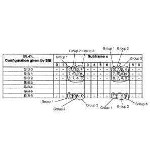
25 memories including computer program code. The one or more memories and
the
computer program code are configured to, with the one or more processors,
cause the
apparatus to perform at least the following: the operations for any method as
described
above in reference to FIG. 15.
[00128] A computer program product comprises a computer-readable
storage medium bearing computer program code embodied therein for use with a
computer. The computer program code comprises code for performing any method
as
described above in reference to FIG. 15.
[00129] An apparatus comprises means for performing the
functions of any
method as described above in reference to FIG. 15.
[00130] Turning to FIG. 16, FIG. 16 is assumed to be performed by an eNB
175, e.g., under direction of the HARQ ACK resource allocation unit 151. The
blocks in
CA 02925372 2016-03-24
WO 2015/043873
PCT/EP2014/068344
26
FIG. 16 may be considered to be interconnected means or units for performing
the
function(s) in the blocks. In block 1610, the eNB 175 transmits a DL data
transmission in
a downlink subframe. In block 1620, the eNB 175 determines one or more
resources to
be used for reception of error information for the received transmission in an
uplink
subframe based at least on an association set between one or more downlink or
special
subframes and an uplink subframe. The determined association set depends on a
downlink reference configuration. The association set for each uplink subframe
comprises
a grouping of the downlink or special subframes into at least two groups. An
association
set is defined only for the subframes which are uplink subframes in a
corresponding
downlink reference configuration. In block 1630, the eNB 175 receives error
(e.g., HARQ-
ACK) information using the determined one or more resources in the uplink
subframe.
[00131] Block 1525 has been described above in reference to
FIG. 15.
[00132] Another exemplary embodiment is a method as shown in
FIG. 16,
wherein the association for each uplink subframe comprises a grouping of the
downlink
subframes into at least two groups.
[00133] A further exemplary embodiment is the method of the
previous
paragraph, wherein a first group comprises the following: downlink subframes
that are,
according to a DL reference configuration, defined as DL or special subframes
and are
associated with a same UL subframe as a SIB-1 configured DL or special
subframes with
a same index.
[00134] A further exemplary embodiment is the method of the
previous
paragraph, wherein a second group comprises subframes that are, according to a
SIB-1
indication, downlink or a special subframe and do not belong to the first
group.
[00135] A further exemplary embodiment is the method of the
previous
paragraph, wherein a third group comprises downlink or special subframes that
are,
according to a SIB-1 indication, uplink subframes or do not belong to any
other group.
[00136] A further exemplary embodiment is the method of the
previous
paragraph, wherein determining the one or more resources to be used for
reception of
HARQ-ACK information comprises, for each uplink subframe, mapping downlink
subframes belonging to the first group into resources with lowest indices,
followed by the
DL subframes belonging to the second group mapped to resources with second
lowest
indices, and the downlink subframes belonging to the third group mapped to
resources
with largest indices.
[00137] A further exemplary embodiment is any method as
described above
in reference to FIG. 16, wherein determining the one or more resources to be
used for
reception of HARQ-ACK information comprises for a DL reference configuration
of five,
CA 02925372 2016-03-24
WO 2015/043873
PCT/EP2014/068344
27
using the a table shown in FIG. 9 to map downlink subframes into groups as
indicated by
FIG. 9.
[00138] A further exemplary embodiment is any method as
described above
in reference to FIG. 16, wherein determining the one or more resources to be
used for
reception of HARQ-ACK information comprises for a DL reference configuration
of two,
using the a table shown in FIG. 10 to map downlink subframes into groups as
indicated by
the FIG. 10.
[00139] A further exemplary embodiment is any method as
described above
in reference to FIG. 16, wherein determining the one or more resources to be
used for
transmission of error information comprises using a table as shown in FIG. 18
for
subframes in the first to determine uplink subframes to use corresponding to
downlink
reference configuration and to uplink-downlink configuration given by system
information
block-1.
[00140] A further exemplary embodiment is any method as
described above
in reference to FIG. 16, wherein the method is applied only by a user
equipment
configured to a certain mode. The method of this paragraph, where the certain
mode is a
time division duplexing mode or an enhanced interference management and
traffic
adaptation mode.
[00141] An apparatus includes one or more processors and one or
more
memories including computer program code. The one or more memories and the
computer program code are configured to, with the one or more processors,
cause the
apparatus to perform at least the following: the operations for any method as
described
above in reference to FIG. 16.
[00142] A computer program product comprises a computer-readable
storage medium bearing computer program code embodied therein for use with a
computer. The computer program code comprises code for performing any method
as
described above in reference to FIG. 16.
[00143] An apparatus comprises means for performing the
functions of any
method as described above in reference to FIG. 16.
[00144] In addition to the above, the existing TDD principle for implicit
HARQ-ACK resource allocation may be used when mapping CCEs corresponding to
different PDCCH OFDM symbols/subframes into PUCCH Format 1/1a/1b resources. In
another embodiment, it's possible to use further optimized mapping
corresponding to
PUCCH resources of Group 2 and Group 3 (but not for Group 1). For example, it
would be
possible to use "subframe first" mapping for those groups (instead of "PDCCH
symbol
first").
CA 02925372 2016-03-24
WO 2015/043873
PCT/EP2014/068344
28
[00145] Advantages and technical effects of the exemplary
embodiments
include one or more of the following non-limiting examples:
[00146] 1) The exemplary embodiments are fully backwards
compatible
such that resource collisions with non-eIMTA UEs are avoided completely
(without the
eNB scheduler based solution / scheduling restrictions)
[00147] 2) A large advantage is that the exemplary embodiments
minimize
the PUCCH resource space and hence the UL overhead. The PUCCH resources do not
need to be dimensioned according to the maximum number of HARQ ACK resources
as
the unoccupied resources will automatically appear in the end of the PUCCH
region.
[00148] o The
smaller number of DL subframes in the selected UL-DL
configuration, the smaller resource needed for PUCCH.
[00149] o
The unoccupied PUCCH resources can be used for PUSCH
[00150] 3) The implementation can be handled easily via two
additional
tables in 3GPP TS 36.213 specification.
[00151] 4) A solution for elMTA PUCCH RA should be specified in any
case to avoid complex scheduler restrictions.
[00152] FIGS. 17 and 18 are different ways of looking at the
information in
FIG.s 9 and 10. Specifically, FIG. 17 is a subframe indexing table for
subframes for which
elMTA and non-eIMTA UEs have the same timing (Group 1 subframes). The subframe
offset values for Group 1 for both FIG. 9 (DL reference configuration 5) and
FIG. 10 (DL
reference configuration 2) are in the table in FIG. 17. FIG. 17 additionally
shows DL
reference configuration 4. Meanwhile, FIG. 18 is a subframe indexing table for
subframes
for which elMTA and non-eIMTA UEs have the different timing (Groups 2 and 3
subframes). The subframe offset values for Groups 2 and 3 for both FIG. 9 (DL
reference
configuration 5) and FIG. 10 (DL reference configuration 2) are in the table
in FIG. 18.
FIG. 18 additionally shows DL reference configuration 4.
[00153] In FIG. 17, there is a "(6)" listed. This represents a
case when there
exists subframe indexes in the DL association set corresponding to SIB-1 UL-DL
configuration, which are not present in DL association set corresponding to
the DL
reference UL-DL configuration. In this case, an elMTA UE needs to reserve the
PUCCH
resources according to the subframe indicated in the parenthesis, but should
not map any
HARQ-ACK onto those resources to avoid resource collisions.
[00154] Embodiments herein may be implemented in software
(executed by
one or more processors), hardware (e.g., an application specific integrated
circuit), or a
combination of software and hardware. In an example embodiment, the software
(e.g.,
application logic, an instruction set) is maintained on any one of various
conventional
CA 02925372 2016-03-24
WO 2015/043873
PCT/EP2014/068344
29
computer-readable media. In the context of this document, a "computer-readable
medium" may be any media or means that can contain, store, communicate,
propagate or
transport the instructions for use by or in connection with an instruction
execution system,
apparatus, or device, such as a computer, with one example of a computer
described and
depicted, e.g., in FIG. 4. A computer-readable medium may comprise a computer-
readable storage medium (e.g., memories 125, 155, 171 or other device) that
does not
encompass propagating signals but may be any media or means that can contain
or store
the instructions for use by or in connection with an instruction execution
system,
apparatus, or device, such as a computer.
[00155] If desired, the different functions discussed herein may be
performed in a different order and/or concurrently with each other.
Furthermore, if
desired, one or more of the above-described functions may be optional or may
be
combined.
[00156] Although various aspects of the invention are set out
in the
independent claims, other aspects of the invention comprise other combinations
of
features from the described embodiments and/or the dependent claims with the
features
of the independent claims, and not solely the combinations explicitly set out
in the claims.
[00157] It is also noted herein that while the above describes
example
embodiments of the invention, these descriptions should not be viewed in a
limiting sense.
Rather, there are several variations and modifications which may be made
without
departing from the scope of the present invention as defined in the appended
claims.
[00158] The following abbreviations that may be found in the
specification
and/or the drawing figures are defined as follows:
3GPP third generation partnership project
ACK acknowledgement
A/N, ACK/NACK acknowledgement/negative acknowledgement
ARO ACK/NACK Resource Offset
CCE Control Channel Element
CSI Channel State Information (includes CSI,
PMI, RI,
and PTI)
D Downlink subframe
DL Downlink (from base station to UE)
ECCE Enhanced CCE
elMTA Enhanced Interference Management and Traffic
Adaptation
eNB Enhanced Node B (LTE base station)
CA 02925372 2016-03-24
WO 2015/043873
PCT/EP2014/068344
EPDCCH Enhanced Physical Downlink Control Channel
F Flexible subframe
HARQ Hybrid Automatic Repeat reQuest
LTE Long Term Evolution
5 MME Mobility Management Entity
MS milliseconds
NACK Negative ACK
OFDM Orthogonal Frequency Division Multiplex
PDCCH Physical Downlink Control Channel
10 PDSCH Physical Downlink Control Channel
PHICH Physical HARQ Indicator Channel
PUCCH Physical Uplink Control Channel
PUSCH Physical Uplink Shared Channel
RA Resource Allocation
15 RAN Radio Access Network
RB Resource Block
Rel Release
RRC Radio Resource Control
S Special subframe
20 SF Subframe
SIB System Information Block
SGW Serving GateWay
SPS Semi-Persistent Scheduling
SRI Scheduling Request Indicator
25 TD-LTE Time-Division-Long Term Evolution
TDD Time Division Duplexing
U Uplink subframe
UE User Equipment
UL Uplink (from UE to base station)
30 WI Work Item
WG Working Group