Note: Descriptions are shown in the official language in which they were submitted.
CA 2925594 2017-03-31
SPIN COATER FOR APPLYING MULTIPLE COATINGS TO AN OPTICAL
SUBSTRATE
FIELD
[0002] The present invention relates to spin coaters, such as a spin coater
having
at least one integrated curing station or line for applying multiple coatings
to an
optical substrate, in a sequence that is selected from a plurality of possible
sequences.
BACKGROUND
[0003] Spin coating processes and associated spin coating machines,
generally
called spin coaters, are typically used to provide a uniform coating on a
substrate.
Spin coating processes have been used to form coated substrates, such as
lenses,
including optical lenses.
[0004] Existing spin coaters are typically used in a production line for
the
application of a single type or class of coating material, and are often
followed in the
production line by a pre-set curing station, such as a thermal curing oven, or
a UV
curing station, or an IR curing station. The type of and settings associated
with the
curing station depends upon the type of coating material that is applied in
the spin
coating station. This results in difficulty with regard to quickly switching
the
production line for the application of different coating materials, such as
for different
substrates and/or different final products, as generally the coating material
reservoir
and the dispensing nozzle assembly must be purged and cleaned to accommodate
the change in coating material. An additional difficulty relates to the curing
station,
which may not be suitable for curing other coating compositions.
[0005] It would be desirable to develop new spin coating assemblies that
can
accommodate different coating compositions. It would be further desirable that
such
Page 1 of 28
CA 02925594 2016-03-24
WO 2015/054041
PCT/US2014/058943
newly developed spin coating assemblies be able to accommodate a plurality of
different coating compositions.
SUMMARY
[0006] In accordance with the present invention there is provided, a spin
coater
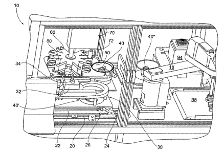
that comprises: (a) a coater bowl configured to collect excess coating
material
expelled from an optical substrate being coated; (b) a rotatable chuck
configured to
receive the optical substrate within the coater bowl and configured to rotate
the
optical substrate during coating; (c) a plurality of coating reservoirs, in
which each
reservoir contains a coating composition (of material) for selectively coating
the
optical substrate; and (d) an indexable coating reservoir platform containing
the
plurality of coating reservoirs, which is configured to index a selected
coating
reservoir into a dispensing position above the coater bowl. The spin coater
can, with
some embodiments, be used with an optical substrate.
[0007] In accordance with the present invention there is further provided,
a spin
coater that comprises: (a) a coater bowl configured to collect excess coating
material
expelled from an optical substrate being coated; (b) a rotatable chuck
configured to
receive the optical substrate within the coater bowl, and which is configured
to rotate
the optical substrate during coating; (c) at least one of coating reservoir,
in which
each reservoir contains a coating composition (or material) for selectively
coating the
optical substrate; and (d) each coating reservoir includes an elongated barrel
containing a moveable piston for dispensing a coating composition from the
coating
reservoir. With some embodiments, each coating reservoir dispenses a coating
composition through a valve-less dispensing orifice positioned at the distal
end of the
barrel.
[0008] In accordance with the present invention there is additionally
provided, a
spin coater that comprises: (a) a coater bowl configured to collect excess
coating
material expelled from an optical substrate being coated; (b) a rotatable
chuck
configured to receive the optical substrate within the coater bowl, and which
is
configured to rotate the optical substrate during coating; (c) a plurality of
coating
reservoirs, in which each reservoir contains a coating composition (or
material) for
selectively coating the optical substrate; and (d) at least one distinct
curing station,
where each distinct curing station is independently configured to selectively
and at
Page 2 of 28
CA 02925594 2016-03-24
WO 2015/054041
PCT/US2014/058943
least partially cure at least one coating composition applied to the optical
substrate.
With some embodiments, each distinct curing station independently includes at
least
one of: (i) a thermal curing station; (ii) a UV curing station; (iii) an IR
curing station;
and (iv) combinations of at least two of (i) through (iv).
[0009] The features that characterize the present invention are pointed out
with
particularity in the claims, which are annexed to and form a part of this
disclosure.
These and other features of the invention, its operating advantages and the
specific
objects obtained by its use will be more fully understood from the following
detailed
description in which non-limiting embodiments of the invention are illustrated
and
described.
BRIEF DESCRIPTION OF THE DRAWINGS
[0010] FIG. 1 is a representative perspective view of a spin coater
according some
embodiments of the present invention;
[0011] FIG. 2 is a representative schematic plan view of a modified
embodiment of
the spin coater of FIG. 1;
[0012] FIG. 3 is representative a section view of a washing/drying station
of the
spin coater of FIG. 1;
[0013] FIG. 4 is a representative section view of an indexable coating
reservoir
platform containing a plurality of coating reservoirs and a dispensing unit of
the spin
coater of FIG. 1;
[0014] FIG. 5 is a representative section view of a coating reservoir of
the spin
coater of FIG. 1; and
[0015] FIG. 6 is a representative section view of a curing station of the
spin coater
of FIG. 1.
[0016] In FIG's 1-6 like characters refer to the same components and
elements,
as the case may be, unless otherwise stated.
DETAILED DESCRIPTION
[0017] The terms "optical," "optically clear," and similar terms as used
herein
mean that the specified material (such as a substrate, film, coating, etc.)
exhibits a
Page 3 of 28
CA 02925594 2016-03-24
WO 2015/054041
PCT/US2014/058943
light transmission value (transmits incident light) of at least 4 percent, and
exhibits a
haze value of less than 1 percent (such as, a haze value of less than 0.5
percent)
when measured at 550 nanometers by, for example, a Haze Gard Plus Instrument.
[0018] As used herein the term "ophthalmic" means pertaining to or
associated
with the eye and vision. As used herein the term "ophthalmic substrate" means
a
substrate, such as a lens, that is ophthalmic. As used herein the terms "lens"
and
"lenses" means and encompasses at least, individual lenses, lens pairs,
partially
formed (or semi-finished) lenses, fully formed (or finished) lenses, and lens
blanks.
Examples of ophthalmic substrates, articles or elements include, but are not
limited
to, corrective and non-corrective lenses, including single vision or multi-
vision lenses,
which can be either segmented or non-segmented multi-vision lenses (such as,
but
not limited to, bifocal lenses, trifocal lenses, and progressive lenses), as
well as other
elements used to correct, protect, or enhance (cosmetically or otherwise)
vision,
including without limitation, contact lenses, intra-ocular lenses, magnifying
lenses,
protective lenses, protective visors, and protective shields.
[0019] As used herein, the term "transparent," such as used in connection
with a
substrate, film, material, and/or coating, means that the indicated substrate,
(such as
coating, film and/or material) has the property of transmitting light without
appreciable
scattering so that objects lying beyond are visibly observable.
[0020] As used herein, the term "coating" means a supported film derived
from a
flowable coating composition, which can optionally have a uniform thickness,
and
specifically excludes polymeric sheets. By contrast, as used herein the term
"sheet"
means a pre-formed film having a generally uniform thickness and which is
capable
of self-support. A sheet has two opposing surfaces, in which at least one
surface
thereof can have thereover one or more layers (including coating layers). As
used
herein, the terms "layer" and "film" each encompass both coatings (such as a
coating
layer or a coating film) and sheets, and a layer can include a combination of
separate
layers, including sub-layers and/or over-layers. In accordance with some
embodiments, and as used herein, the term "coating" means, within appropriate
context, the process of applying a coating composition (or material) to the
substrate
to form a coating (or coating layer).
Page 4 of 28
CA 02925594 2016-03-24
WO 2015/054041
PCT/US2014/058943
[0021] As used herein, the terms "cure," "cured," and related terms, means
that at
least a portion of the polymerizable and/or crosslinkable components that form
a
curable composition are at least partially polymerized and/or crosslinked. In
accordance with some embodiments, the degree of crosslinking can range from 5%
to 100% of complete crosslinking. In accordance with some further embodiments,
the degree of crosslinking can range from 30% to 95%, such as 35% to 95%, or
50%
to 95%, or 50% to 85% of complete crosslinking. The degree of crosslinking can
range between any combination of these recited lower and upper values,
inclusive of
the recited values.
[0022] As used herein, the articles "a," "an," and "the" include plural
referents
unless otherwise expressly and unequivocally limited to one referent.
[0023] Unless otherwise indicated, all ranges or ratios disclosed herein
are to be
understood to encompass any and all subranges or subratios subsumed therein.
For
example, a stated range or ratio of "1 to 10" should be considered to include
any and
all subranges between (and inclusive of) the minimum value of 1 and the
maximum
value of 10; that is, all subranges or subratios beginning with a minimum
value of 1 or
more and ending with a maximum value of 10 or less, such as but not limited
to, 1 to
6.1, 3.5 to 7.8, and 5.5 to 10.
[0024] Unless otherwise indicated, all numbers expressing dimensions,
physical
properties, and so forth used in the specification and claims, are to be
understood as
modified in all instances by the term "about."
[0025] As used herein, the term "valve-less" means being free of a valve
(not
including a valve).
[0026] As used herein, the spin coater of the present invention is also
referred to
as a flexible spin coater for purposes including, but not limited to,
indicating the
flexibility the spin coater of the present invention can provide with regard
to applying
a plurality of coating compositions in a sequence that can be selected from a
plurality
of coating application sequences.
[0027] As used herein the term "IR" means infrared, such as infrared
radiation.
[0028] As used herein the term "UV" means ultraviolet, such as ultraviolet
radiation.
Page 5 of 28
CA 02925594 2016-03-24
WO 2015/054041
PCT/US2014/058943
[0029] The various embodiments and examples of the present invention as
presented herein are understood to be illustrative of the present invention
and not
restrictive thereof and are non-limiting with respect to the scope of the
invention.
[0030] With non-limiting reference to the drawings, FIG. 1 is a
representative
perspective view of a flexible spin coater 10 that includes, or has associated
therewith, integrated curing stations, for selectively applying multiple
coatings to an
optical substrate in accordance with some embodiments of the present
invention.
With reference to FIG. 2, there is depicted a representative schematic plan
view of a
modified embodiment of the spin coater 10 of FIG. 1.
[0031] The flexible spin coater 10 as described herein, and in accordance
with
some embodiments, provides a low cost, small scale (such as, producing up to
100
coated optical substrates per hour) top side spin coating machine that can
include a
surface pretreatment station (such as, but not limited to, plasma pretreatment
station)
that cleans, coats (utilizing one or more of multiple coatings and
combinations of
coatings), and which utilizes one or more of several different curing methods
(such
as, UV, IR, and/or thermal curing apparatae) or combinations thereof. The spin
coater of the present invention can, with some embodiments, be operated with
the
formation of minimal waste streams and/or waste materials.
[0032] The spin coater of the present invention can have any suitable
dimensions,
which can, with some embodiments, be appropriately scaled to the space, such
as a
room, in which the spin coater is placed for operation. With some embodiments,
the
spin coater of the present invention, including an enclosure, a control panel,
and a
filter (such as a high-efficiency particulate air or HEPA filter) has a width
of from 0.76
meters (m) to 1.52 m (2.5 to 5 feet), or from 0.91 m to 1.37 m (3 to 4.5
feet); a length
of from 0.91 m to 3.66 m (3 to 12 feet), or from 0.91 m to 3.05 m (3 to 10
feet), or
from 1.22 m to 2.13 m (4 to 7 feet); and a height of from 1.83 m to 3.05 m (6
to 10
feet), or from 2.13 m to 2.74 m (7 to 9 feet).
[0033] The flexible spin coater 10 can, with some embodiments, be used to
coat a
variety of substrates, such as, but not limited to, optical substrates.
Examples of
optical substrates that can be coated with the spin coater of the present
invention
include, but are not limited to, piano lenses, prescription lenses, which in
each case
can be finished lenses, unfinished lenses, or lens blanks. In accordance with
some
Page 6 of 28
CA 02925594 2016-03-24
WO 2015/054041
PCT/US2014/058943
further embodiments, the lenses coated with the spin coater of the present
invention,
have a diameter of 50-85 mm with varied back curvatures (such as, from 1/2
base
up to 10 base). For reference a finished lens is one that will have the front
and rear
surface of the lens formed (commonly by grinding and polishing) to the desired
contour, while a semi-finished lens will have only one (e.g., the top) surface
finished.
Both finished and unfinished lens often undergo further processing such as
coating
with photochromic material, hard coats, tinting layers, planarizing layers
(generally
categorized as coating layers providing optical, aesthetic or protective
properties) as
well as edging to fit the desired shape or other processing to couple to a
frame or
support structure.
[0034] The optical substrate that is coated with the method of the present
invention can, with some embodiments, be formed from and correspondingly
include
organic materials, inorganic materials, or combinations thereof (for example,
composite materials).
[0035] Examples of organic materials that can be used as optical substrates
in
accordance with various embodiments of the present invention, include
polymeric
materials, such as homopolynners and copolymers, prepared from the monomers
and
mixtures of monomers disclosed in U.S. Patent 5,962,617 and in U.S. Patent
5,658,501 from column 15, line 28 to column 16, line 17. For example, such
polymeric materials can be thermoplastic or thermoset polymeric materials, can
be
transparent or optically clear, and can have any refractive index required.
Examples
of such monomers and polymers include: polyol(ally1 carbonate) monomers, e.g.,
allyl
diglycol carbonates such as diethylene glycol bis(ally1 carbonate), which
monomer is
sold under the trademark CR-39 by PPG Industries, Inc.; polyurea-polyurethane
(polyurea-urethane) polymers, which are prepared, for example, by the reaction
of a
polyurethane prepolymer and a diamine curing agent, a composition for one such
polymer being sold under the trademark TRIVEX by PPG Industries, Inc.;
polyol(meth)acryloyl terminated carbonate monomer; diethylene glycol
dimethacrylate
monomers; ethoxylated phenol methacrylate monomers; diisopropenyl benzene
monomers; ethoxylated trimethylol propane triacrylate monomers; ethylene
glycol
bismethacrylate monomers; poly(ethylene glycol) bismethacrylate monomers;
urethane acrylate monomers; poly(ethoxylated bisphenol A dimethacrylate);
poly(vinyl acetate); poly(vinyl alcohol); poly(vinyl chloride);
poly(vinylidene chloride);
Page 7 of 28
CA 02925594 2016-03-24
WO 2015/054041
PCT/US2014/058943
polyethylene; polypropylene; polyurethanes; polythiourethanes; thermoplastic
polycarbonates, such as the carbonate-linked resin derived from bisphenol A
and
phosgene, one such material being sold under the trademark LEXAN; polyesters,
such as the material sold under the trademark MYLAR; poly(ethylene
terephthalate);
polyvinyl butyral; poly(methyl methacrylate), such as the material sold under
the
trademark PLEXIGLAS, and polymers prepared by reacting polyfunctional
isocyanates with polythiols or polyepisulfide monomers, either homopolymerized
or
co-and/or terpolymerized with polythiols, polyisocyanates, polyisothiocyanates
and
optionally ethylenically unsaturated monomers or halogenated aromatic-
containing
vinyl monomers. Also contemplated are copolymers of such monomers and blends
of the described polymers and copolymers with other polymers, for example, to
form
block copolymers or interpenetrating network products.
[0036] With some embodiments of the present invention, the optical
substrate can
be an ophthalmic substrate. Examples of organic materials suitable for use in
forming ophthalmic substrates include art-recognized polymers that are useful
as
ophthalmic substrates, such as organic optical resins that are used to prepare
optically clear castings for optical applications, such as ophthalmic lenses.
[0037] Examples of inorganic materials that can be used as optical
substrates with
some embodiments of the present invention include glasses, minerals, ceramics,
and
metals. With some embodiments, the optical substrate can include glass. In
other
embodiments, the optical substrate can have a reflective surface, for example,
a
polished ceramic substrate, metal substrate, or mineral substrate. In other
embodiments, a reflective coating or layer (e.g., a metal layer, such as a
silver layer)
can be deposited or otherwise applied to a surface of an inorganic or an
organic
substrate to make it reflective or to enhance its reflectivity.
[0038] Optical substrates that can be used with the method according to
some
embodiments of the present invention can also include untinted, tinted,
linearly
polarizing, circularly polarizing, elliptically polarizing, photochromic, or
tinted-
photochromic substrates. As used herein with reference to optical substrates,
the
term "untinted" means optical substrates that are essentially free of coloring
agent
additions (such as conventional dyes) and have an absorption spectrum for
visible
radiation that does not vary significantly in response to actinic radiation.
Further, with
reference to optical substrates the term "tinted" means substrates that have a
Page 8 of 28
CA 02925594 2016-03-24
WO 2015/054041
PCT/US2014/058943
coloring agent addition (such as conventional dyes) and an absorption spectrum
for
visible radiation that does not vary significantly in response to actinic
radiation.
[0039] As used herein, the term "circularly polarizing" with reference to
optical
substrates refers to optical substrates that are adapted to circularly
polarize
electromagnetic radiation. As used herein, the term "elliptically polarizing"
with
reference to optical substrates refers to optical substrates that are adapted
to
elliptically polarize electromagnetic radiation. Further, as used herein, with
reference
to optical substrates, the term "tinted-photochromic" means optical substrates
containing a coloring agent addition as well as a photochromic material, and
having
an absorption spectrum for visible radiation that varies in response to at
least actinic
radiation. Thus, for example, a tinted-photochromic substrate can have a first
color
characteristic of the coloring agent and a second color characteristic of the
combination of the coloring agent and the photochromic material when exposed
to
actinic radiation.
[0040] With some embodiments, an initial step in the use of the flexible
spin coater
of the invention involves loading (see reference or step 12 of FIG. 2) the
optical
substrates into a surface treatment chamber, such as plasma chamber 14. The
plasma surface treatment conducted within chamber 14 can be selected from one
or
more art-recognized plasma surface treatment methods including, but not
limited to,
corona treatment, atmospheric plasma treatment, atmospheric-pressure
treatment,
flame plasma treatment, and/or chemical plasma treatment. With some
embodiments, the surface treatment conducted in chamber 14 is an oxygen plasma
treatment. The loading step 12 allows an operator to visually inspect the
optical
substrates (or lenses) for defects or damage before the process is begun. If
dirt is
visible the operator can clean the lenses by hand prior to placement into the
plasma
chamber 14 where they will undergo plasma treatment. The hand cleaning step
can,
with some embodiments, be conducted with deionized air. With some alternative
embodiments, the operator can wipe the lenses, as needed, with one of several
cleaning agents such as alcohol (such as isopropanol), or aqueous isopropanol,
or an
aqueous detergent.
[0041] The surface treatment process involves, with some embodiments,
treating
the surface of the optical substrate to promote wetting and enhance adhesion
of a
coating that is subsequently applied to and formed thereon. The chamber 14,
with
Page 9 of 28
CA 02925594 2016-03-24
WO 2015/054041
PCT/US2014/058943
some embodiments, includes a series of edge engaging optical substrate holders
to
allow the maximum surface treatment of the optical substrates in chamber 14.
Chamber 14, with some embodiments, is operated under conditions of reduced
atmosphere, and correspondingly the surface treatment is conducted as a batch
process operation in chamber 14.
[0042] Plasma treatments, including corona treatments, provide a clean and
efficient method of altering the surface properties of an optical substrate,
such as
roughening and/or chemically altering one or more surfaces thereof, without
altering
the bulk properties of the optical substrate. With some embodiments, one or
more
inert gases (such as, but not limited to, argon and/or nitrogen) and/or one or
more
reactive gases (such as, but not limited to, oxygen, CO, and/or CO2) can be
used as
the gas in chamber 14 from which the plasma is formed. Inert gases, with some
embodiments,roughen the surface of optical substrates. Reactive gases, such as
oxygen, with some embodiments can both roughen and chemically alter the
surface
exposed to the plasma by, for example, forming hydroxyl and/or carboxyl groups
on
the treated surface.
[0043] With some embodiments, the use of oxygen in the plasma surface
treatment process can provide an effective degree of physical roughening and
chemical modification of the surface of the optical substrate, which can
improve
adhesion without detrimentally effecting other properties, such as optical
properties,
of the optical substrate. Atmospheric air can also be used to form the plasma
gas,
and with some embodiments is a reactive gas. The extent of the surface
roughening
and/or chemical modification is, with some embodiments, a function of the
plasma
gas and the operating conditions of chamber 14, including the length of time
of the
surface treatment. With some embodiments, the optical substrates are exposed
to a
plasma surface treatment for 1 to 5 minutes, such as in chamber 14, which
results in
the formation of surface treated optical substrates that are further processed
in spin
coater 10. Surface treatment of the optical substrates within chamber 14 can
also
remove foreign contaminants present on the surface thereof. The presence of
certain
surface contaminants can, with some embodiments, undesirably reduce the
surface
energy of the surface of the optical substrate. A high surface energy, which
can
result after removal of the surface contaminants, promotes coating wetting,
with some
embodiments.
Page 10 of 28
CA 02925594 2016-03-24
WO 2015/054041
PCT/US2014/058943
[0044] Following the plasma surface treatment in chamber 14, the surface
treated
optical substrates are removed at step 16 and can optionally be subjected to
visual
and/or automated inspection prior to placement onto a loading unit 20 of spin
coater
10. The optical substrates are forwarded along a path of travel 22 on loading
unit 20,
which can be achieved by way of a conveyer, such as a conveyer belt. The
optical
substrates are forwarded along path of travel 22, until they engage a
positioning
pocket 24. The loading unit 20 queues the optical substrates, and prevents the
optical substrates from damaging each other (such as by
engaging/rubbing/knocking
each other) while sequentially presenting and introducing each individual
optical
substrate into positioning pocket 24. The edges of the positioning pocket 24
are
configured, such as angled, to position each individual optical substrate in a
pre-
selected position (such as a centered position or location) relative to the
width of the
positioning pocket. Positioning pocket 24 also includes, with some
embodiments, at
least one (such as at least two) proximity sensors (such as beam breaking
sensors
26) that identify the leading edge and/or trailing edge of each individual
optical
substrate, and cause the conveyor to stop when the optical substrate is sensed
and
determined to be properly positioned (such as centered) within positioning
pocket 24.
[0045] Positioning pocket 24 allows spin coater 10 to be automated with a
pick
and place robotic arm 18 (shown only in FIG. 1). Robotic arm 18 engages the
optical
substrate in a manner that maintains a known center position of the optical
substrate,
such as within about 2 mm, throughout the process steps conducted in spin
coater
10. The known center position of the optical lens can be so maintained as a
result of
a combination of, the accuracy of robotic arm 18, and the proper initial
positioning of
the optical substrate by and within positioning pocket 24, with some
embodiments.
The use of a pick and place robotic arm 18 allows spin coater 10 to be fully
automated within the envelope of robotic arm 18, and minimizes damage to, such
as
marking of, the surfaces of the optical substrate, compared to a manual
process,
such as a fully manual process.
[0046] The optical substrate can be wet or dry when picked up by robotic
arm 18.
With some embodiments, when wet, the optical substrate includes one or more
wet
coating layers thereon that are not hard, such as being tacky and/or uncured.
With
some further embodiments, when dry, the optical substrate is free of coating
layers or
includes one or more dry coating layers that are hard (and not tacky), such as
being
Page 11 of 28
CA 02925594 2016-03-24
WO 2015/054041
PCT/US2014/058943
cured. In accordance with some embodiments, a lower portion of the gripper
elements of robotic arm 18 engage and secure the optical substrate during wet
pick
up thereof (when the optical substrate is wet). With some further embodiments,
upper portions of the gripper elements of robotic arm 18 engage and secure the
lens
during dry pick up thereof (when the optical substrate is dry).
[0047] The placement at step 12 into chamber 14 and removal from chamber 14
at step 16 can each be automated with a pick and place robotic arm, which
moves
the positioning pocket 24 (or other positioning mechanism) upstream of chamber
14,
with some embodiments. The use of an operator at chamber 14 allows for visual
inspection of the optical substrates both before placement in and after
removal from
chamber 14, and allows for human oversight and control over spin coater 10
during
operation thereof, with some embodiments. Art-recognized automated inspection
procedures and equipment can be used to inspect the optical substrates before
and/or after treatment thereof in chamber 14 in conjunction with or in place
of manual
inspection thereof, with some embodiments.
[0048] Robotic arm 18 moves the optical substrate in step 28 to an optional
washing and drying station 30, shown in FIG. 3. With some embodiments, robotic
arm 18 places the optical substrate on a rotatable chuck 40', which can be a
rotatable
vacuum chuck 40' with some embodiments, within the washing and drying station
30.
Rotatable chuck 40' is programmable and can rotate at high speeds, such as up
to
4,000 rpm, with some embodiments. After securing the optical substrate onto
rotatable chuck 40', a top 32 is slid to a closed position aligning high
pressure water
spray nozzles 34 with the optical substrate held on the rotating chuck 40'.
The high
pressure water spray nozzles 34 are angled relative to the surface including
the edge
of the optical substrate held on the rotating vacuum chuck 40' for the
purposes of
cleaning the optical substrate, with some embodiments. In this manner the
entire
upper surface and edge of the plasma treated optical substrate can be cleaned,
such
as with deionized water under conditions of elevated pressure, such as about
1,000
psi, with some embodiments. Rotatable chuck 40' can rotate during spray
washing to
assure even cleaning of the optical substrate surface. The washing parameters,
such
as liquid pressure, washing time, and rotating speed can be programmable and
can
vary based on parameters, such as the type and/or size of the optical
substrate,
plasma treatment, and/or subsequent coating processes.
Page 12 of 28
CA 02925594 2016-03-24
WO 2015/054041
PCT/US2014/058943
[0049] Following washing, the optical substrate can, with some embodiments
be
dried in station 30 by one or more drying methods including, but not limited
to, high
speed rotation of the rotatable chuck 40' and/or high speed air nozzle(s) 36,
which
can be filtered air nozzles. The drying parameters can be programmed in a
manner
similar to those associated with the washing parameters, with some
embodiments.
[0050] Following washing and drying in station 30, the top 32 is slid to an
open
position, robotic arm 18 reengages the optical substrate on rotatable chuck
40', and
robotic arm 18 moves the optical substrate in step 48 to the rotatable chuck
40 in the
coater bowl 50, which can be a rotatable vacuum chuck 40 with some
embodiments.
The rotatable chuck 40 is configured to receive the optical substrate within
coater
bowl 50 and configured to rotate the optical substrate during coating, the
speed and
timing of which can vary depending upon parameters including, but not limited
to, the
coating and optical substrate.
[0051] The coater bowl 50 is configured to collect: excess coating material
expelled from the optical substrate that is coated therein; and/or expelled
during
purging of the reservoirs 80 discussed further herein; and/or cleaning
materials that
are periodically utilized to clean coater bowl 50 (such as at the end of the
week, or
day, or shift). The spin coater 10 of the present invention is effective as a
once
through system for small scale production, with some embodiments. A once
through
system means that the collected materials need not be recirculated and thus
the
collected material from coater bowl 50, can be removed through a drain not
shown,
need not be segregated or processed for reuse. A once through system allows
for
the efficient change out of distinct coating materials, with some embodiments.
[0052] The spin coater 10 of the present invention includes, with some
embodiments, an indexable coating reservoir platform 60 containing a plurality
of
coating reservoirs 80. Indexable coating reservoir platform 60 is configured
to index
a selected coating reservoir 80 into a dispensing position above coater bowl
50, so
the coating reservoir 80 can be dispensed with a dispensing unit 70 at the
dispensing
position as shown in FIG. 4. The dispensing unit 70 is engagable with the
selected
coating reservoir 80 in the dispensing position to dispense a select (or pre-
determined) amount of coating material from the engaged and selected coating
reservoir 80.
Page 13 of 28
CA 02925594 2016-03-24
WO 2015/054041
PCT/US2014/058943
[0053] The indexable coating reservoir platform 60 is a rotatable carousel
having
distinct circumferential positions, in which each distinct circumferential
position
reversibly receives one of the plurality of disposable coating reservoirs 80.
The
carousel can, with some embodiments include eight- or ten-stations. The
carousel
can have other numbers of positions for reservoirs 80, with some further
embodiments, such as, but not limited to, eighteen- or twenty-stations. The
rotating
carousel as shown represents an efficient embodiment for forming and operating
the
indexable coating reservoir platform 60. Other indexing arrangements, however,
can
be used in accordance with the spin coater of the present invention. For
purposes of
non-limiting illustration, a linearly moving rack or line of reservoirs 80 can
be used for
forming platform 60, with no limit on the number of distinct reservoirs 80
that can be
present in such an arrangement. The motor rotating the platform 60 can utilize
a
variety of art-recognized alignment mechanisms, such as a spring biased detent
locking mechanism, to assure the held reservoirs 80 are moved into precise and
predetermined indexed positions such that the reservoir 80 is in the
dispensing
position below and aligned with the dispensing unit 70.
[0054] FIG. 5 is a representative section view of an individual coating
reservoir 80
of the flexible spin coater 10. Each coating reservoir 80 includes an
elongated barrel
82 containing a moveable piston 84 for dispensing of coating material from the
coating reservoir 80, and in which advancement of moveable piston 84 of the
selected coating reservoir 80 in the dispensing position dispenses coating
material
from the selected coating reservoir 80. With some embodiments and with further
reference to FIG. 5, each coating reservoir 80 is formed as a disposable
plastic
syringe and thus each coating reservoir 80 dispenses coating through a valve-
less
dispensing orifice 86 at the distal end of the barrel. Plastic syringes are
commercially
available and are particularly well suited to form reservoirs 80 due to the
precise
dispensing characteristics associated there-with. Caps (not shown) on the rear
surface and across the orifice 86 can be used for shipping of filled
reservoirs 80, with
some embodiments. The caps can also be reapplied for removal and storage of
reservoirs 80, with some further embodiments.
[0055] With some embodiments, barrel 82 of each reservoir 80 allows for the
printing of human and/or machine readable identification indicia on the
optical
substrate, such as, but not limited to bar codes, QR codes, and/or matrix
codes.
Page 14 of 28
CA 02925594 2016-03-24
WO 2015/054041
PCT/US2014/058943
Machine readable identification indicia can include information relating to,
the coating
identification, the coating parameters associated with a particular coating
material,
and/or the type of optical substrate, with some embodiments. The coating
parameters can include, with some embodiments, one or more of: the unit dosage
of
coating material for a given substrate (such as from 0.2 ml to 0.6 ml for
conventional
lens coatings); the rate of dispensing; the dispensing pattern (such as, start
in the
center of the vacuum chuck held substrate and move out, vice versa, or some
other
varied dispensing position); the speed of the vacuum chuck 40 (sometimes
called
spread speed); and/or the time of rotation (also called spread time).
[0056] The narrow orifice 86 of reservoir 80 (with some embodiments in
combination with the movable piston 84) allows the coating material to be held
in
reservoir 80 and dispensed in the absence of a valve. With some embodiments,
the
valve-less dispenser of reservoir 80 substantially eliminates (except for a
single purge
drip/drop) priming which is necessary with other spin coater dispensers, and
greatly
reduces the amount of waste formed during operation of spin coater 10.
[0057] Dispensing unit 70 includes a rod 72 aligned with the selected
reservoir 80
in the dispensing position and is configured to selectively advance the
moveable
piston 84 of the selected coating reservoir 80 in the dispensing position to
dispense a
select (or predetermined) unit amount of coating material from the engaged
selected
coating reservoir 80. With some embodiments, rod 72 is a screw, such as an
elongated screw. With some embodiments, the select (or predetermined) unit
amount of coating material dispensed is from 0.2 ml to 4 ml, or from 0.2 to 1
ml, or
from 0.2 ml to 0.6 ml. The unit amount includes a coating amount and a purge
amount (such as a drop) and can vary depending on parameters, including but
not
limited to, the coating material, the substrate characteristics, the desired
coating
thickness, and coating protocol.
[0058] With some embodiments, the selected coating reservoir 80 has therein
an
amount of coating material that is less than that required to coat two optical
substrates, but more than that required to coat a single optical substrate
(i.e., less
than two unit amounts). This remainder amount of coating material (i.e., less
than
two unit amounts) can with some embodiments be: (i) expelled from coating
reservoir
80 for disposal, such as into a disposal receptacle or drain; or (ii)
dispensed from
coating reservoir 80 onto a single optical substrate. After expelling or
dispensing the
Page 15 of 28
CA 02925594 2016-03-24
WO 2015/054041
PCT/US2014/058943
remainder amount of coating material, reservoir 80 is empty and substantially
free of
coating material, and can be disposed of as solid waste, with some
embodiments.
[0059] The dispensing unit 70, with some embodiments, includes a motor 200,
such as a linear stepper motor or the like, for precisely advancing the
moveable
piston 84 of a selected coating reservoir to dispense there-from a
predetermined
amount of coating material. Dispensing unit 70 also senses, with some
embodiments, the position of piston 84, via rod 72 or other device, both
before and
after use, so that the amount of coating material residing in each specific
reservoir 80
can be calculated and tracked by spin coater 10. Dispensing unit 70 lifts rod
72 out
of barrel 82 to allow for indexing of the carousel of platform 60 to select a
distinct
reservoir 80, with some embodiments. A reservoir 80 moving out of the
dispensing
position will not be empty, but will have remaining therein coating material
for
selective later use, with some embodiments.
[0060] In accordance with some embodiments of the present invention, rod 72
is a
stationary rod and the motor is moveable, such as vertically moveable, along
rod 72.
The motor can include an extension (not shown) that engages abuttingly with
piston
84. Controllable movement of the motor, such as vertically downward, along the
stationary rod serves to drive piston 84 into reservoir 80, which results in
dispensing
of a select (or predetermined) amount of coating material from orifice 86,
with some
embodiments.
[0061] In operation, the indexable coating reservoir platform 60, the
reservoirs 80,
and the unit 70 are moveable as a unit, shown schematically at 78, at least
between:
(i) a purge position, where the selected coating reservoir 80 in the
dispensing position
is above the coater bowl 50 but is not above the optical substrate or lens;
and (ii) at
least one dispensing position, where the selected coating reservoir in the
dispensing
position above the coater bowl is above the optical substrate. The coater bowl
50 can
be constructed to include a trough or extension that extends to a point
aligned with
the purge position. In the purge position the movable piston 84 is advanced by
rod 72
of unit 70 to dispense a minimal purging drop of the coating material to clear
the outer
surface of the meniscus of coating material at orifice 86 of valve-less
reservoir 80.
The outer surface of the meniscus can be exposed to air during non-use of the
coating material in a given reservoir 80, which can result in oxidation and/or
fouling
the meniscus, thus requiring purging thereof. A single drop is all that is
required to
Page 16 of 28
CA 02925594 2016-03-24
WO 2015/054041
PCT/US2014/058943
prime the coating material distribution system by purging the possibly non-
homogeneous portion of the coating material from orifice 86, with some
embodiments. Following the initial purge drop, the indexable coating reservoir
platform 60, the reservoirs 80, and the unit 70 are moveable as a single unit,
shown
schematically at 78, to at least one dispensing position where the selected
coating
reservoir 80 in the dispensing position above the coater bowl 50 is above the
optical
substrate.
[0062] With some embodiments, orifice 86 is dimensioned so that the coating
material within barrel 82 of reservoir 80 does not flow out therefrom, in the
absence of
movable piston 84 being positioned (or moved) within barrel 82 towards orifice
86.
With some embodiments, orifice 86 is circular and has a diameter of less than
or
equal to 3.18 mm (1/8 inch).
[0063] The movement 78 of the selected dispensing reservoir 80 allows the
spin
coater 10 to accommodate a variety of dispensing protocols for coating the
optical
substrate on rotatable chuck 40 within coater bowl 50. With some embodiments,
the
coating material from the selected dispensing reservoir 80 can be dispensed on
the
optical substrate at the center, and/or at one or more select positions across
the
surface of the optical substrate (such as in a line, spiral, and/or concentric
circles,
across/on the upper surface of the optical substrate), and then the rotatable
chuck 40
is engaged to spin the applied coating material to form a coating layer having
substantially uniform thickness. In accordance with some further embodiments,
concurrently with spinning of rotatable chuck 40, the coating material from
the
selected dispensing reservoir 80 is dispensed on the optical substrate at the
center,
and/or at one or more select positions across the surface of the optical
substrate to
form a uniform coating. Any desired combination of these dispensing and
spinning
protocols can be used with the spin coater 10. Additionally the dispensing
rate and
the spinning speed can also be varied throughout the process, with some
embodiments. Intermittent dispensing and/or spinning of the vacuum chuck can
used
with some embodiments. The dispensing protocols are, with some embodiments,
based upon parameters including, but not limited to, the substrate composition
and/or
surface treatment thereof, the coating material applied, and/or the desired
final
coating parameters.
Page 17 of 28
CA 02925594 2016-03-24
WO 2015/054041
PCT/US2014/058943
[0064] The indexable platform 60 allows the spin coater 10 to apply a
single or
multiple coating layers on the optical substrate without removing the lens
from the
rotatable chuck 40. With some embodiments and for purposes of non-limiting
illustration, in a first stage a first coating layer is applied using one
selected reservoir
80, then the carousel is indexed, such that in a second stage a second coating
material is applied over the first coating layer from a distinct/separate
reservoir 80.
The indexing of the carousel can be done with the platform 60 moved away from
alignment of the reservoirs 80 with the optical substrate, so no stray drips
from
intermediate reservoirs 80 interfere with the desired coating protocol, and so
that in
the second stage the second coating material can be properly purged before
dispensing over the optical substrate. Having two or more coating stages
allows the
spin coater of the present invention to apply and form numerous combinations
of
stacked coating layers, in which each coating layer thereof has the same or
different
composition and/or the same or different thickness relative to an adjacent (or
abutting) coating layer.
[0065] In accordance with some embodiments of the present invention, the
spin
coater includes or has integrated therewith at least one distinct curing
station (such
as curing stations 92, 94, and 96) for selectively and independently curing
(such as at
least partially curing) each coating applied to the optical substrate. The
spin coater
includes or has integrated therewith, with some further embodiments, a
plurality of
distinct curing stations (such as two or more curing stations, such as curing
stations
92, 94, and 96) for selectively and independently curing (such as at least
partially
curing) each coating applied to the optical substrate. Following the
application of the
desired coating material at coating bowl 50, robotic arm 18 reengages the
optical
substrate and moves it, at step 88, to a designated curing station (92, 94, or
96).
With some embodiments of the present invention, each curing station
independently
includes at least one of: (i) a thermal curing station 96; (ii) a UV curing
station 94; (iii)
an IR curing station 92; and (iv) combinations of at least two of (I), (ii),
and (iii).
[0066] FIG. 6 is a representative section view of a UV curing station 94 of
the
flexible spin coater 10 showing a sliding drawer with a work piece holding a
rotatable
chuck 40" (which can be a rotatable vacuum chuck 40" with some embodiments)
for
selective receipt of a desired optical substrate to be cured. A concave or
angled
reflective mirror 203 surrounds rotatable chuck 40" to assist or improve in
edge
Page 18 of 28
CA 02925594 2016-03-24
WO 2015/054041
PCT/US2014/058943
curing. With a coated optical substrate on rotatable chuck 40" of UV curing
station
94, the drawer is closed and a shutter opened to expose the coated optical
substrate
to UV light (such as from a mercury or metal halide bulb) within UV curing
station 94.
Rotatable chuck 40" can rotate at slow speeds within UV curing station 94 to
further
assure a uniform cure, with some embodiments. The curing time within UV curing
station 94 can vary depending on, for example, the particular coating. The IR
curing
station 92 can have a similar construction as UV curing station 94, but
includes an
appropriate IR source. The curing time within IR curing station 92 can also
vary
depending on, for example, the particular coating. Each curing station, with
some
embodiments, can include therein an atmosphere selected from an inert
atmosphere
(such as, but not limited to, argon and/or nitrogen) and/or a reactive
atmosphere
(such as, but not limited to, oxygen, CO, and/or CO2).
[0067] The thermal curing station 96, with some embodiments, is accompanied
with a throughput conveyor 98 and a discharge or accumulation area 100. In the
thermal curing station the optical substrates to be thermally cured are placed
on the
input conveyer, such as side-by-side on conveyor 98. The speed of the conveyor
is
selected so the coated optical substrates have a desired temperature exposure
within
curing station 96. The oven of thermal curing station 96 can, with some
embodiments be an electric oven and/or a gas fired oven (such as a natural gas
fired
oven). The curing times and temperature profiles can vary depending on, for
example, the coating that is to be cured. With some embodiments, the coated
optical
substrates are exposed to a temperature of 115 -135 C for 20-40 minutes, such
as
30 minutes at 125 C for 30 minutes within the thermal curing station.
Following at
least partial curing, the coated optical substrates are forwarded to an
accumulation
area 100 designed to accommodate a desired number of optical substrates with
no
edges touching there-between (such as, but not limited to, up to 30 coated
optical
substrates).
[0068] With some embodiments, conveyor 98 in concert with robotic arm 18 is
used for egress of at least partially cured coated optical substrates from the
IR curing
station and/or the UV curing station. With some embodiments, a separate exit
conveyor (not shown) is used to bypass the thermal curing station 96 for
purposes of
delivering coated optical substrates to accumulation area 100.
Page 19 of 28
CA 02925594 2016-03-24
WO 2015/054041
PCT/US2014/058943
[0069] In accordance with some further embodiments, an optical substrate
can be
washed, then coated, then re-washed, and then subsequently coated with the
same
or different coating material before curing. With some additional embodiments,
a
coated and cured optical substrate can be returned from a curing station (92,
94, or
96) to: (i) the washing and drying station; and/or (ii) coater bowl 50 for the
application
thereto of a subsequent coating material. An optical substrate can, with some
embodiments, be moved from accumulation area 100 back to loading unit 20 for
the
subsequent application thereto or one or more coating materials.
[0070] The spin coater of the present invention can, with some embodiments,
be
used for the production of optical substrates, which each independently have
the
same or a different coating stack formed thereon. The spin coater of the
present
invention can be operated so as to produce a minimum of waste, with some
embodiments. The spin coater of the present invention can, with some
embodiments, be at least partially automated, and optionally incorporated into
art-
recognized product tracking and control systems.
[0071] The present invention has been described with reference to specific
details
of particular embodiments thereof. It is not intended that such details be
regarded as
limitations upon the scope of the invention except insofar as and to the
extent that
they are included in the accompanying claims.
Page 20 of 28