Language selection

Search

Patent 2925706 Summary

Third-party information liability

Some of the information on this Web page has been provided by external sources. The Government of Canada is not responsible for the accuracy, reliability or currency of the information supplied by external sources. Users wishing to rely upon this information should consult directly with the source of the information. Content provided by external sources is not subject to official languages, privacy and accessibility requirements.

Claims and Abstract availability

Any discrepancies in the text and image of the Claims and Abstract are due to differing posting times. Text of the Claims and Abstract are posted:

  • At the time the application is open to public inspection;
  • At the time of issue of the patent (grant).
(12) Patent: (11) CA 2925706
(54) English Title: SOLAR ENERGY COLLECTOR AND SYSTEM FOR USING SAME
(54) French Title: COLLECTEUR D'ENERGIE SOLAIRE ET SON SYSTEME D'UTILISATION
Status: Granted
Bibliographic Data
(51) International Patent Classification (IPC):
  • F24S 20/20 (2018.01)
  • F24S 10/40 (2018.01)
  • F24S 10/70 (2018.01)
  • F24S 23/30 (2018.01)
  • F24S 23/70 (2018.01)
(72) Inventors :
  • IM, DO SUN (United States of America)
(73) Owners :
  • IM, DO SUN (United States of America)
(71) Applicants :
  • IM, DO SUN (United States of America)
(74) Agent: CASSAN MACLEAN IP AGENCY INC.
(74) Associate agent:
(45) Issued: 2017-05-16
(86) PCT Filing Date: 2014-05-20
(87) Open to Public Inspection: 2015-04-02
Examination requested: 2016-12-13
Availability of licence: N/A
(25) Language of filing: English

Patent Cooperation Treaty (PCT): Yes
(86) PCT Filing Number: PCT/US2014/038685
(87) International Publication Number: WO2015/047456
(85) National Entry: 2016-03-29

(30) Application Priority Data:
Application No. Country/Territory Date
14/041,337 United States of America 2013-09-30

Abstracts

English Abstract

A solar energy collector includes a first member having a cavity and a longitudinal axis. The first member has a longitudinal window forming a part thereof and a body forming another part thereof. The longitudinal window is made of a material adapted to be transparent to solar radiation. The body has an exterior absorptive surface and an interior reflective surface. A second member is located within the cavity of the first member and is generally parallel to longitudinal axis of the first member. The second member is adapted to carry an energy absorbing fluid. An insulative material fills the cavity between the first member and the second member. A solar energy collection system includes the form going solar energy collector and a solar energy transmitting device for directing solar energy through the window of the collector.


French Abstract

L'invention concerne un collecteur d'énergie solaire, qui comprend un premier élément ayant une cavité et un axe longitudinal. Le premier élément a une fenêtre longitudinale formant une partie de ce dernier et un corps formant une autre partie de ce dernier. La fenêtre longitudinale est faite d'un matériau conçu pour être transparent à un rayonnement solaire. Le corps comprend une surface absorbante extérieure et une surface réfléchissante intérieure. Un second élément est placé à l'intérieur de la cavité du premier élément et est sensiblement parallèle à l'axe longitudinal du premier élément. Le second élément est conçu pour transporter un fluide d'absorption d'énergie. Un matériau isolant remplit la cavité entre le premier élément et le second élément. Un système de collecte d'énergie solaire comprend le collecteur d'énergie solaire ci-dessus et un dispositif de transmission d'énergie solaire pour diriger l'énergie solaire à travers la fenêtre du collecteur.

Claims

Note: Claims are shown in the official language in which they were submitted.

CLAIMS:
1. A solar energy collector comprising: a first tubular member having a
circular
cross-section, a first end, a second end, a cavity, and a longitudinal axis,
the first
member consisting of a longitudinal one-way mirrored window extending the
entire
length between the first end and the second end of the first member and
forming a part
of the first member and a body forming the rest of the first member, said
longitudinal
one-way mirrored window being made of a material adapted to pass solar
radiation,
said body having an exterior absorptive surface and an interior reflective
surface, the
interior reflective surface covering the entire interior surface of the body;
a second
tubular member having a circular cross-section, being located within the
cavity of the
first member and generally parallel to said longitudinal axis, and being
surrounded by
the interior reflective surface of the first member, said second member being
adapted to
carry an energy absorbing fluid; and an insulative material filling the cavity
between the
first member and the second member, said insulative material being a fluid or
a
vacuum.
2. The solar energy collector of claim 1 wherein said material adapted to
pass solar
energy being selected from the group consisting of: glass, plastic, or
combinations
thereof.
9

3. The solar energy collector of claim I wherein said exterior absorptive
surface
being a black surface.
4. The solar energy collector of claim 1 wherein said interior reflective
surface being
a mirrored surface.
5. The solar energy collector of claim 1 wherein said fluid being a gas.
6. A solar energy collection system comprising: a solar energy collector
comprising
a first tubular member having a circular cross-section, a first end, a second
end, a
cavity, and a longitudinal axis, the first member consisting of a longitudinal
one-way
mirrored window extending the entire length between the first end and the
second end
of the first member and forming a part of the first member and a body forming
the rest
of the first member, said longitudinal one-way mirrored window being made of a

material adapted to pass solar radiation, said body having an exterior
absorptive
surface and an interior reflective surface, the interior reflective surface
covering the
entire interior surface of the body; a second tubular member having a circular
cross-
section, being located within the cavity of the first member and generally
parallel to said
longitudinal axis, and being surrounded by the interior reflective surface of
the first
member, said second member being adapted to carry an energy absorbing fluid;
and
an insulative material filling the cavity between the first member and the
second
member, said insulative material being a fluid or a vacuum, and a solar energy

transmitting device adapted to direct solar energy through said window.

7. The solar energy collection system of claim 6 wherein said solar energy
transmitting device being a lens or a mirror,
8. The solar energy collector of claim 6 wherein said material adapted to
pass solar
energy being selected from the group consisting of: glass, plastic, or
combinations
thereof.
9. The solar energy collector of claim 6 wherein said exterior absorptive
surface
being a black surface_
10. The solar energy collector of claim 6 wherein said interior reflective
surface being
a mirrored surface.
11. The solar energy collector of claim 6 wherein said fluid being a gas_
12. The solar energy collector of claim 1, wherein the second tubular
member being
generally co-axial with said longitudinal axis.
13. The solar energy collector of claim 6, wherein the second tubular
member being
generally co-axial with said longitudinal axis.
11

Description

Note: Descriptions are shown in the official language in which they were submitted.


CA 02925706 2016-03-29
WO 2015/047456 PCT/US2014/038685
SOLAR ENERGY COLLECTOR AND SYSTEM FOR USING SAME
Field of the Invention
The present invention is directed to a solar energy collector and a system for

using same.
Background of the Invention
Solar energy is a renewable energy source. There is on-going development of
ways to bring solar energy into a commercial status by increasing its
conversion
efficiency.
Solar energy refers to the radiant energy (heat and light) produced by the Sun

and captured, for example, on the Earth. It is estimated that about
3.8x10⁶exajoules
(EJ) per year of solar energy is absorbed by the Earth. If some of this solar
energy can
be harnessed for use, it could have a significant impact on energy
supply/demand.
Solar energy technologies generally are categorized into either passive or
active
capture categories. Active capture refers to, for example, the use of
photovoltaic
panels or solar thermal collectors. While passive capture refers to, for
example,
orienting buildings, or choosing materials, or designing spaces to maximize
solar energy
use.
1

CA 02925706 2016-03-29
WO 2015/047456
PCT/US2014/038685
Captured thermal solar energy may be used in a variety of applications, such
as,
but not limited to, water heating, space heating, space cooling, and process
heat
generation. In the capture of thermal solar energy, it is important to make
the collector
as efficient as possible, so that the return on the capital employed may be
maximized.
Accordingly, there is a need for a solar energy collector that efficiently
captures
solar energy.
Summary of the Invention
A solar energy collector includes a first member having a cavity and a
longitudinal axis. The first member has a longitudinal window forming a part
thereof and
a body forming another part thereof. The longitudinal window is made of a
material
adapted to be transparent to solar radiation. The body has an exterior
absorptive
surface and an interior reflective surface. A second member is located within
the cavity
of the first member and is generally parallel to longitudinal axis of the
first member. The
second member is adapted to carry an energy absorbing fluid. An insulative
material
fills the cavity between the first member and the second member. A solar
energy
collection system includes the form going solar energy collector and a solar
energy
transmitting device for directing solar energy through the window of the
collector.
2

CA 02925706 2016-03-29
WO 2015/047456 PCT/US2014/038685
Description of the Drawings
For the purpose of illustrating the invention, there is shown in the drawings
a
form that is presently preferred; it being understood, however, that this
invention is not
limited to the precise arrangements and instrumentalities shown.
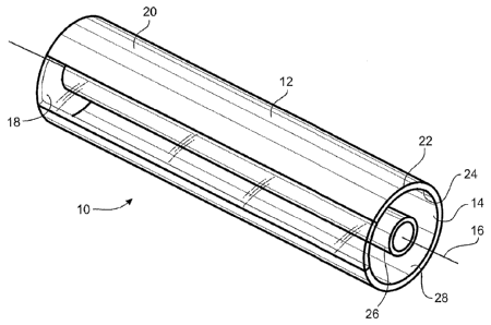
Figure 1 is an illustration of the solar energy collector.
Figure 2 is an illustration of one embodiment of the system for using the
solar
energy collector.
Figure 3 is an illustration of another embodiment of the system for using the
solar
energy collector.
Description of the Invention
Referring to the drawings, where like numerals refer to like elements, there
is
shown in Figure 1 a solar energy collector 10. In general, collector 10
comprises a first
member 12 and a second member 26 with an insulative material located between
the
first member 12 and second member 22.
First member 12 is generally an elongated member having a longitudinal axis
16.
Member 12 may have any cross-section shape; in one embodiment, the cross-
sectional
shape is circular (i.e., first member 12 is a tube). First member 12 has a
cavity 14. First
member 12 includes a longitudinal window 18 forming a part of the member 12
and a
body 20 forming another part of member 12.
3

CA 02925706 2016-03-29
WO 2015/047456
PCT/US2014/038685
Window 18 is generally parallel to the longitudinal axis 16. Window 18 may
form
a part of the wall of member 12. Window 18 is adapted to transmit solar energy
into
cavity 14. Window 18 should not allow solar energy to escape from the cavity
14. In
this regard, window 18 may be an 'one-way' mirror that allows radiation in,
but prevents
it escape, such as provided by a polarized film. Window 18 may be glass or
plastic.
Body 20 may form the rest of the first member 12. Body 20 has an exterior (or
outer) surface 22 and an interior (or inner) surface 24. The choice of
material for the
body 20 may be dependent of several factors including: strength at the maximum

anticipated temperature, insulative properties, resistance to corrosion, and
cost, to
name a few.
The exterior surface 22 is adapted to absorb solar radiation. The exterior
surface
22 may be a coating on the body or may be layer laminated to the body or may
be
integral with the body. In one embodiment, the exterior surface 22 may be a
black
surface, so as to simulate an idealized black body. The idealized black body
may be
characterized as a physical body that absorbs all incident electromagnetic
radiation
(including solar radiation), regardless of frequency or angle of incident.
The interior surface 24 is adapted to reflect solar radiation. The interior
surface
24 may be a coating on the body or may be layer laminated to the body or may
be
integral with the body. In one embodiment, the interior surface 24 is a
mirrored surface,
so as to reflect all radiation incident to it without absorbing any of that
radiation.
4

CA 02925706 2016-12-13
WO 2015/047456
PCT/US2014/038685
=
Second member 26 is generally an elongated member having a longitudinal axis.
Second member 26 may be located anywhere within cavity 14 of the first member
12.
Member 26 may have any cross-section shape; in one embodiment, the cross-
sectional
shape is circular (i.e., second member 25 is a tube). In one embodiment, the
second
member 26 is co-axial with the axis 16 of the first member 12. Second member
26 is
adapted, in one aspect, to carry an energy absorbing fluid therethrough.
Second
member 26 is also adapted, in another aspect, to capture solar energy or allow
the solar
energy to pass, efficiently, to the energy absorbing fluid. With regard to the
later aspect,
second member 26 may be black, so as to simulate the idealized black body,
discussed
above, Second member 26 may be made of glass (e.g., Pyrex ), quartz, ceramic,
plastic, metal, or combinations thereof. The choice of material for the second
member
26 may be dependent of several factors including: strength at the maximum
anticipated
temperature, insulative properties, resistance to corrosion, and cost, to name
a few.
The gap or space between the body 20 and the second member 26 may be any
distance. Several considerations must be kept in mind when considering the
width of
the this gap.. Those considerations include: the focal length and dimension of
the solar
energy director, discussed below; the lager the diameter of the body 20, the
better for
collecting solar radiation, but the worse for thermal insulation.
The energy absorbing fluid may be any fluid. For example, the fluid may be
either a liquid or a gas. The choice of the fluid is not limiting, and may be
dictated by

CA 02925706 2016-03-29
WO 2015/047456
PCT/US2014/038685
how the captured energy is to be subsequently used. In one embodiment, the
energy
absorbing fluid may be a mixture of water and ethylene glycol. In another
embodiment,
the energy absorbing fluid may be water.
Insulative material 28 occupies the space between the first member 12 and the
second member 26. Insulative material 28 may be any material adapted to
transmit the
solar energy entering the window 18 as efficiently as possible (i.e.,
absorbing as little
radiant energy as possible). Insulative material may be a fluid or a vacuum.
The fluid
may be a gas.
Referring to Figures 2 and 3, system 30 for utilizing solar energy collector
10 are
illustrated. In general, system 30 includes the solar energy collector 10, a
solar energy
director 32, a energy absorbing fluid mover 34, and thermal energy utilizier
36.
The solar energy director 32 directs and concentrates the solar radiation.
Director 32 may be a lens (Figure 2) or a reflector (Figure 3). Director 32
may be
elongated and with an axis generally parallel to the axis 16 of the first
member 12. The
focal point of the director may be positioned so as to direct the focused
radiation at the
second member 26 of the collector 10. The lens may be any lens; in one
embodiment
may be a convex lens. The lens may also be Fresnel lens. The reflector may be
any
reflector or mirror. In one embodiment, the reflector may be a parabolic
reflector.
6

CA 02925706 2016-03-29
WO 2015/047456
PCT/US2014/038685
The energy absorbing fluid mover 34 may be device adapted to move the fluid
around the system 30. In one embodiment, the mover 34 may be a pump (if the
fluid is
a liquid). In another embodiment, the mover 34 may be a compressor (if the
fluid is a
gas).
The thermal energy utilizer 36 may be any device adapted to use the energy
absorbed in the energy absorbing fluid pasted from the collector 10. For
example, the
utilizer 36 may be used for water heating, space heating, space cooling, and
process
heat generation or to pre-heat fluids used in any of those operations.
Examples
In the following example, the inventive collector is compared to a
conventional
collector to demonstrate the efficacy of the inventive collector. The tests
were
performed on a sunny day with an ambient temperature of 90 F, and all tested
were
exposed to sunlight for 5 minutes (tests were run simultaneously). In each, 5
cc of tap
water was placed in a test tube (simulating the second member) with a
thermometer for
measuring the temperature of the water. Test 1-3 are of conventional set-ups,
while
test 4 is directed to the inventive collector. In test 1, the water in the
test tube was
heated without any director or the first member and the temperature reached
110 F. In
test 2, the water was heated, in the test tube, using a 2x4 inch parabolic
mirror with its
focal line directed on the test tube and the temperature reached 120 F. In
test 3, the
water was heated, in the test tube, using a lens with its focal line directed
on the test
tube and the temperature reached 120 F. In test 4, the water was heated, in
the test
7

CA 02925706 2016-12-13
WO 2015/047456
PCT/LIS- 2014/41386S5
tube and the first member, using a 2x4 inch cylindrical convex lens with its
focal line
directed through the window and on the test tube and the temperature
reached.139 F.
. .
=
8 =

Representative Drawing
A single figure which represents the drawing illustrating the invention.
Administrative Status

For a clearer understanding of the status of the application/patent presented on this page, the site Disclaimer , as well as the definitions for Patent , Administrative Status , Maintenance Fee  and Payment History  should be consulted.

Administrative Status

Title Date
Forecasted Issue Date 2017-05-16
(86) PCT Filing Date 2014-05-20
(87) PCT Publication Date 2015-04-02
(85) National Entry 2016-03-29
Examination Requested 2016-12-13
(45) Issued 2017-05-16

Abandonment History

There is no abandonment history.

Maintenance Fee

Last Payment of $125.00 was received on 2024-04-22


 Upcoming maintenance fee amounts

Description Date Amount
Next Payment if standard fee 2025-05-20 $347.00
Next Payment if small entity fee 2025-05-20 $125.00

Note : If the full payment has not been received on or before the date indicated, a further fee may be required which may be one of the following

  • the reinstatement fee;
  • the late payment fee; or
  • additional fee to reverse deemed expiry.

Patent fees are adjusted on the 1st of January every year. The amounts above are the current amounts if received by December 31 of the current year.
Please refer to the CIPO Patent Fees web page to see all current fee amounts.

Payment History

Fee Type Anniversary Year Due Date Amount Paid Paid Date
Application Fee $200.00 2016-03-29
Maintenance Fee - Application - New Act 2 2016-05-20 $50.00 2016-03-29
Request for Examination $400.00 2016-12-13
Final Fee $150.00 2017-04-04
Maintenance Fee - Patent - New Act 3 2017-05-23 $50.00 2017-05-18
Maintenance Fee - Patent - New Act 4 2018-05-22 $50.00 2018-05-16
Maintenance Fee - Patent - New Act 5 2019-05-21 $100.00 2019-05-15
Maintenance Fee - Patent - New Act 6 2020-05-20 $100.00 2020-05-11
Maintenance Fee - Patent - New Act 7 2021-05-20 $100.00 2021-04-08
Maintenance Fee - Patent - New Act 8 2022-05-20 $100.00 2022-05-09
Maintenance Fee - Patent - New Act 9 2023-05-23 $100.00 2023-04-19
Maintenance Fee - Patent - New Act 10 2024-05-21 $125.00 2024-04-22
Owners on Record

Note: Records showing the ownership history in alphabetical order.

Current Owners on Record
IM, DO SUN
Past Owners on Record
None
Past Owners that do not appear in the "Owners on Record" listing will appear in other documentation within the application.
Documents

To view selected files, please enter reCAPTCHA code :


To view images, click a link in the Document Description column. To download the documents, select one or more checkboxes in the first column and then click the "Download Selected in PDF format (Zip Archive)" or the "Download Selected as Single PDF" button.

List of published and non-published patent-specific documents on the CPD .

If you have any difficulty accessing content, you can call the Client Service Centre at 1-866-997-1936 or send them an e-mail at CIPO Client Service Centre.


Document
Description 
Date
(yyyy-mm-dd) 
Number of pages   Size of Image (KB) 
Abstract 2016-03-29 1 65
Claims 2016-03-29 3 76
Drawings 2016-03-29 2 44
Description 2016-03-29 8 255
Representative Drawing 2016-03-29 1 17
Cover Page 2016-04-14 2 51
Claims 2016-12-13 3 85
Description 2016-12-13 8 245
Maintenance Fee Payment 2018-05-16 1 33
Maintenance Fee Payment 2019-05-15 1 33
Office Letter 2019-09-19 2 37
International Search Report 2016-03-29 2 93
National Entry Request 2016-03-29 3 89
Amendment 2016-12-13 9 298
Final Fee 2017-04-04 1 25
Representative Drawing 2017-04-24 1 17
Cover Page 2017-04-24 1 51