Note: Descriptions are shown in the official language in which they were submitted.
- 1 -
Fluidic Module, Device and Method for Aliquoting a Liquid
Description
The present invention relates to a fluidic module, a device for aliquoting a
liquid and a
method of aliquoting a liquid. Embodiments relate to parallel-pneumatic
metering and
aliquoting.
In centrifugal microfluidics, rotors are used for processing liquids.
Corresponding rotors
contain chambers for collecting liquid and channels for directing fluid. While
the rotor is
being subjected to centripetal acceleration, the liquid is pressed radially
outward and can
thus arrive at a radially outward position by directing fluid correspondingly.
Centrifugal
microfluidics is employed, for example, in the field of life sciences, in
particular in
laboratory analytics. Centrifugal microfluidics serves to automate process
flows while
replacing operations such as pipetting, mixing, metering, aliquoting and
centrifuging.
Aliquoting of liquids is required in particular at the beginning, during or at
the end of a
process chain so as to perform several mutually independent detection
reactions
(verification reactions) with one sample. For parallelizing laboratory
processes within a
centrifugal-microfluidic rotor in a fully automated manner, aliquoting
processes are
therefore indispensable. In this context, certain analysis methods require not
only
aliquoting of an individual liquid volume into several aliquots, but also
aliquoting of several
different liquid volumes, the aliquots of which in turn need to be further
processed ¨ e.g.,
mixed with one another. Quantitatively meaningful analysis processes can be
performed
only if the aliquots comprise volumes defined as accurately as possible. For
this reason,
each aliquoting step should always also be combined with a metering step. This
also
applies in case different aliquoting steps take place in parallel within a
centrifugal-
microfluidic rotor.
Godino et al. [Lab Chip, 2013, 13, 685-69, Figure 1] describes a metering
structure
containing a single compression chamber comprising an inlet channel and an
outlet
channel. The compression chamber consists of two sections extending radially
outward
(on the left and on the right) and a section extending radially inward. In
this context, a
defined partial volume can be collected by the left-hand section. Any excess
liquid volume
exceeding the volume of the left-hand section does not remain within the left-
hand section
and therefore cannot be separated off either.
CA 2925839 2017-12-21
CA 02925839 2016-03-30
- 2 -
However, one possibility of aliquoting defined amounts of liquid is not shown.
Moreover,
the metering structure taken from Godino et al. is workable only for liquid
volumes that
have strict upper limits since the overflow structure is contained within the
compression
.. chamber. Metering will therefore only work when the overflow chamber is not
full.
Moreover, said structure allows no aliquoting, as was already mentioned. In
addition, the
metering structure contains very broad inflow channels, as a result of which
the metered
volume will highly depend on the input volume.
What is also known is utilizing a compression chamber in combination with
fluid channels
exhibiting different hydraulic resistances. For example, Zehnle et al. (Lab
Chip, 2012, 12,
5142-5145, Figure 2) shows pumping of liquid within a centrifuge rotor from a
radially
outward point to a radially inward point without using any external auxiliary
devices.
However, the fluid structure described there enables neither metering nor
aliquoting.
US 5,409,665 describes how end cavities within a centrifugal-microfluidic
rotor can be
filled, via a supply channel extending radially outward, with ends extending
radially inward.
In this context, the end cavities are vented, so that air can escape from the
end cavities
during the filling process. Subsequently, the supernatant liquid above the end
cavities is
discharged via the supply channel and a siphon.
DE 10 2008 003 979 B3 describes how metering channels within a centrifugal-
microfluidic
rotor can be filled via a supply channel extending radially inward. The ends
of the
metering channels have end cavities located thereat. Since the end cavities
are not
vented, the air which flows from the metering channels into the end cavities
while the
metering channels are being filled cannot escape and is compressed. While the
corresponding pneumatic pressure counteracts the centrifugal pressure of the
liquid within
the metering channels, the supernatant present will be discharged in the
supply channel.
By subsequently increasing the rotary frequency of the rotor, the liquid/gas
interface
between the liquid contained within the metering channels and the air
contained within the
end cavities becomes unstable, so that the compressed gas will escape from the
end
cavity through the liquid phase within the metering channel, and so that said
liquid phase
can be transferred to the end cavity.
In US 5,409,665 and DE 102008003979 B3, aliquots are generated within end
cavities.
Further fluidic processing of the aliquots is not possible, however.
- 3 -
It is thus the object of the present invention to provide an improved concept
for aliquoting
a liquid.
Embodiments of the present invention provide a fluidic module comprising a
first
measuring chamber, a second measuring chamber, a first fluid inlet channel
connected to
the first measuring chamber and a second fluid inlet channel connected to the
second
measuring chamber, a first fluid outlet channel connected to the first
measuring chamber
and a second fluid outlet channel connected to the second measuring chamber.
The
fluidic module is configured such that upon rotation of the fluidic module
about a center of
rotation, a liquid is centrifugally driven into the first measuring chamber
via the first fluid
inlet channel and into the second measuring chamber via the second fluid inlet
channel so
that a compressible medium previously present within the first measuring
chamber and
within the second measuring chamber is compressed by the liquid driven into
the first
measuring chamber and into the second measuring chamber. The fluidic module is
further
configured such that upon a reduction of the rotational frequency and upon an
expansion,
resulting therefrom, of the compressible medium, a large part of the liquid
present within
the first measuring chamber is driven out of the first measuring chamber via
the first fluid =
outlet channel, and a large part of the liquid present within the second
measuring chamber
is driven out of the second measuring chamber via the second fluid outlet
channel.
Further embodiments provide a device for aliquoting a liquid. The device
comprises the
above-described fluidic module and a drive. The drive is configured configured
to subject,
in a first phase, the fluidic module to such a rotational frequency that
liquid is centrifugally
driven into the first measuring chamber via the first fluid inlet channel and
into the second
measuring chamber via the second fluid inlet channel, so that a compressible
medium
previously present within the first measuring chamber and within the second
measuring
chamber is compressed by the liquid driven into the first measuring chamber
and into the
second measuring chamber. The drive is further configured to reduce, in a
second phase,
the rotational frequency to which the fluidic module is subjected to such an
extent that due
to the reduction of the rotational frequency and to the expansion, resulting
therefrom, of
the compressible medium, a large part of the liquid present within the first
measuring
CA 2925839 2017-12-21
CA 02925839 2016-03-30
- 4 -
chamber is driven out of the first measuring chamber via the first fluid
outlet channel, and
a large part of the liquid present within the second measuring chamber is
driven out of the
second measuring chamber via the second fluid outlet channel.
Further embodiments provide a method of aliquoting a liquid by means of the
above-
described fluidic module. The method includes subjecting the fluidic module to
such a
rotational frequency that a liquid is centrifugally driven into the first
measuring chamber via
the first fluid inlet channel and into the second measuring chamber via the
second fluid
inlet channel so that a compressible medium previously present within the
first measuring
chamber and within the second measuring chamber is compressed by the liquid
driven
into the first measuring chamber and into the second measuring chamber. The
method
further includes reducing the rotational frequency to which the fluidic module
is subjected,
so that due to the reduction of the rotational frequency and to the expansion,
resulting
therefrom, of the compressible medium, a large part of the liquid present
within the first
measuring chamber is driven out of the first measuring chamber via the first
fluid outlet
channel, and a large part of the liquid present within the second measuring
chamber is
driven out of the second measuring chamber via the second fluid outlet
channel.
Further embodiments of the present invention provide a fluidic module. The
fluidic module
comprises a measuring chamber, a compression chamber connected to the
measuring
chamber via a fluid overflow, a fluid inlet channel connected to the measuring
chamber,
and a fluid outlet channel connected to the measuring chamber. The fluidic
module is
configured such that upon a rotation of the fluidic module about a center of
rotation, a
liquid is centrifugally driven into the measuring chamber via the fluid inlet
channel until
liquid gets into the compression chamber from the measuring chamber via the
fluid
overflow and until a compression, caused by the liquid driven into the
measuring chamber,
of a compressible medium previously present within the measuring chamber,
within the
compression chamber and within the fluid overflow is sufficiently large so
that upon a
reduction of a rotational frequency and upon an expansion, resulting
therefrom, of the
compressible medium, a large part of the liquid present within the measuring
chamber is
driven out of the measuring chamber via the fluid outlet channel. Moreover,
the fluidic
module is configured such that upon a reduction of the rotational frequency
and upon an
expansion, resulting therefrom, of the compressible medium, a large part of
the liquid
present within the measuring chamber is driven out of the measuring chamber
via the fluid
outlet channel.
CA 02925839 2016-03-30
- 5 -
In embodiments, the fluidic module may be configured such that upon a rotation
of the
fluidic module about a center of rotation, the liquid is driven into the
measuring chamber
via the fluid inlet channel by a centrifugal pressure caused by the rotation
and acting upon
.. the liquid, until liquid from the measuring chamber gets into the
compression chamber via
the fluid overflow and until a counter pressure resulting from a compression,
caused by
the liquid driven into the measuring chamber, of a compressible medium
previously
present within the measuring chamber, within the compression chamber and
within the
fluid overflow becomes sufficiently large so that upon a reduction of a
rotational frequency
and upon a reduction, resulting therefrom, of the centrifugal pressure, the
compressible
medium expands and drives a large part of the liquid present within the
measuring
chamber out of the measuring chamber via the fluid outlet channel. Moreover,
the fluidic
module may be configured such that upon the reduction of the rotational
frequency and
the reduction, caused thereby, of the centrifugal pressure, the compressible
medium
expands and drives a large part of the liquid present within the measuring
chamber out of
the measuring chamber via the fluid outlet channel.
Further embodiments provide a device for aliquoting a liquid. The device
comprises the
above-described fluidic module and a drive. The drive is configured to
subject, in a first
phase, the fluidic module to such a rotational frequency that the liquid is
centrifugally
driven into the measuring chamber via the fluid inlet channel until liquid
from the
measuring chamber gets into the compression chamber via the fluid overflow and
until a
compression, caused by the liquid driven into the measuring chamber, of a
compressible
medium previously present within the measuring chamber, within the compression
chamber and within the fluid overflow becomes sufficiently large so that upon
a reduction
of the rotational frequency and upon an expansion, resulting therefrom, of the
compressible medium, a large part of the liquid present within the measuring
chamber is
driven out of the measuring chamber via the fluid outlet channel. Moreover,
the drive is
configured to reduce, in a second phase, the rotational frequency to which the
fluidic
.. module is subjected in such a manner that a large part of the liquid
present within the
measuring chamber is driven out of the measuring chamber via the outlet
channel by the
expansion of the compressible medium, which expansion results from the
reduction of the
rotational frequency.
CA 02925839 2016-03-30
- 6 -
Further embodiments provide a method of aliquoting a liquid by means of the
above-
described fluidic module. The method includes subjecting the fluidic module to
such a
rotational frequency that the liquid is centrifugally driven into the
measuring chamber via
the fluid inlet channel until liquid from the measuring chamber gets into the
compression
chamber via the fluid overflow and until a compression, caused by the liquid
driven into
the measuring chamber, of a compressible medium previously present within the
measuring chamber, within the compression chamber and within the fluid
overflow
becomes sufficiently large so that upon a reduction of the rotational
frequency and upon
an expansion, resulting therefrom, of the compressible medium, a large part of
the liquid
present within the measuring chamber is driven out of the measuring chamber
via the fluid
outlet channel. Moreover, the method includes reducing the rotational
frequency to which
the fluidic module is subjected, so that a large part of the liquid present
within the
measuring chamber is driven out of the measuring chamber via the outlet
channel by the
expansion of the compressible medium, which expansion results from the
reduction of the
rotational frequency.
Embodiments of the present invention will be explained in more detail with
reference to
the accompanying figures, wherein:
Fig. 1 shows a schematic side view for illustrating embodiments of the
present
invention;
Fig. 2 shows a schematic side view for illustrating embodiments of the
present
invention;
Fig. 3a shows a schematic top view of a detail of a fluidic module in
accordance
with an embodiment of the present invention;
Fig. 3b shows a schematic top view of a detail of a fluidic module in
accordance
with an embodiment of the present invention;
Fig. 3c shows a schematic top view of a detail of a fluidic module in
accordance
with an embodiment of the present invention;
Fig. 3d shows a schematic top view of a detail of a fluidic module in
accordance
with an embodiment of the present invention;
CA 02925839 2016-03-30
- 7 -
Fig. 3e shows a schematic top view of a detail of a fluidic module in
accordance
with an embodiment of the present invention;
Fig. 4a shows a schematic top view of a detail of a fluidic module and a
liquid level
within the fluidic module at a first point in time, in accordance with an
embodiment of the present invention;
Fig. 4b shows a schematic top view of the detail of the fluidic module
and a liquid
level within the fluidic module at a second point in time, in accordance with
an embodiment of the present invention;
Fig. 4c shows a schematic top view of the detail of the fluidic module
and a liquid
level within the fluidic module at a third point in time, in accordance with
an
embodiment of the present invention;
Fig. 4d shows a schematic top view of the detail of the fluidic module
and a liquid
level within the fluidic module at a fourth point in time, in accordance with
an embodiment of the present invention;
Fig. 4e shows a schematic top view of the detail of the fluidic module
and a liquid
level within the fluidic module at a fifth point in time, in accordance with
an
embodiment of the present invention;
Fig. 4f shows a schematic top view of the detail of the fluidic module and
a liquid
level within the fluidic module at a sixth point in time, in accordance with
an
embodiment of the present invention;
Fig. 5 shows a schematic top view of a detail of a fluidic module in
accordance
with an embodiment of the present invention;
Fig. 6a shows a schematic top view of a partial detail of the fluidic
module shown in
Fig. 5 and a liquid level within the fluidic module at a first point in time;
Fig. 6b shows a schematic top view of a partial detail of the fluidic
module shown in
Fig. 5 and a liquid level within the fluidic module at a second point in time;
CA 02925839 2016-03-30
- 8 -
Fig. 6c shows a schematic top view of a partial detail of the fluidic
module shown in
Fig. 5 and a liquid level within the fluidic module at a third point in time;
Fig. 6d shows a schematic top view of a partial detail of the fluidic
module shown in
Fig. 5 and a liquid level within the fluidic module at a fourth point in time;
Fig. 6e shows a schematic top view of a partial detail of the fluidic
module shown in
Fig. 5 and a liquid level within the fluidic module at a fifth point in time;
and
Fig. 7 shows a schematic top view of a detail of a fluidic module.
In the subsequent description of the embodiments of the invention, elements
which are
identical or have identical actions will be provided with identical reference
numerals in the
figures, so that their descriptions in the various embodiments are mutually
exchangeable.
Before embodiments of the invention will be explained in more detail, it shall
initially be
pointed out that embodiments of the present invention are employed, in
particular, in the
field of centrifugal microfluidics, which is about processing of liquids
within the nanoliter to
milliliter ranges. Accordingly, the fluidic structures may comprise suitable
dimensions
within the micrometer range for handling corresponding volumes of liquid. The
fluidic
structures (geometric structures) as well as the pertinent methods are
suitable for
metering and/or aliquoting liquid within centrifuge rotors.
When the expression radial is used herein, what is meant in each case is
radial in relation
to the center of rotation about which the fluidic module and/or the rotor is
rotatable. Within
the centrifugal field, therefore, a radial direction away from the center of
rotation is radially
falling, and a radial direction toward the center of rotation is radially
rising. A fluid channel
whose beginning is closer to the center of rotation than is its end, is thus
radially falling,
whereas a fluid channel whose beginning is further away from the center of
rotation than
is its end, is radially rising.
Before an embodiment of a fluidic module having corresponding fluidic
structures will be
addressed in more detail with reference to Figs. 3 and 4, embodiments of an
inventive
device will be described first with reference to Figs. 1 and 2.
CA 02925839 2016-03-30
- 9 -
Fig. 1 shows a device 8 comprising a fluidic module 10 in the form of a body
of rotation
comprising a substrate 12 and a cover 14. The substrate 12 and the cover 14
may be
circular in a plan view and comprise a central opening via which the body of
rotation 10
may be mounted to a rotating part 18 of a drive device via customary fastening
means 16.
The rotating part 18 is pivoted on a stationary part 22 of the drive device
20. The drive
device may be a conventional centrifuge having an adjustable rotational speed
or a CD or
DVD drive, for example. Provision may be made of control means 24 configured
to control
the drive device 20 to subject the body of rotation 10 to rotations at
different rotory
frequencies. As is obvious to persons skilled in the art, the control means 24
may be
implemented, for example, by a computing means programmed accordingly or by an
application integrated circuit. The control means 24 may further be configured
to control
the drive device 20, upon manual inputs on the part of a user, to cause the
necessary
rotations of the body of rotation. In any case, the control means 24 is
configured to control
the drive device 20 to subject the body of rotation to the necessary rotary
frequencies so
as to implement the invention as described herein. As the drive device 20, a
conventional
centrifuge with only one direction of rotation may be used.
The body of rotation 10 comprises the necessary fluidic structures. The
necessary fluidic
structures may be formed by cavities and channels within the cover 14, the
substrate 12
or within the substrate 12 and the cover 14. In embodiments, for example,
fluidic
structures may be formed within the substrate 12, whereas filler openings and
venting
openings are formed in the cover 14.
In an alternative embodiment shown in Fig. 2, fluidic modules 32 are inserted
into a rotor
30 and form, along with the rotor 30, the body of rotation 10. The fluidic
modules 32 may
each comprise a substrate and a cover wherein corresponding fluidic structures
may be
formed in turn. The body of rotation 10 formed by the rotor 30 and the fluidic
modules 32
in turn can be subjected to rotation by a drive device 20 controlled by the
control means
24.
In embodiments of the invention, the fluidic module and/or the body of
rotation which
comprises the fluidic structures may be formed of any suitable material, for
example a
plastic such as PMMA (polymethyl methacrylate, polycarbonate, PVC,
polyvinylchloride)
or PDMS (polydimethylsiloxane), glass or the like. The body of rotation 10 may
be
considered as being a centrifugal-microfluidic platform.
CA 02925839 2016-03-30
- 10 -
Fig. 3a shows a top view of a detail of an inventive fluidic module 50 where a
cover has
been omitted so that the fluidic structures can be seen. The fluidic module 50
shown in
Fig. 3a may have the shape of a disc, so that the fluidic structures are
rotatable about a
center of rotation 52. The disc may comprise a central hole 54 for being
attached to a
drive device, as was explained above for example with reference to Figs. 1 and
2.
The fluidic structures of the fluidic module 50 may comprise a measuring
chamber 60, a
compression chamber 66 connected to the measuring chamber 60 via a fluid
overflow 68,
a fluid inlet channel 70 connected to the measuring chamber 60, and a fluid
outlet channel
.. 72 connected to the measuring chamber 60.
The fluidic module 50 may be configured such that upon a rotation of the
fluidic module 50
about the center of rotation 52, a liquid is centrifugally driven into the
measuring chamber
60 via the fluid inlet channel 70 until liquid from the measuring chamber 60
gets into the
compression chamber 66 via the fluid overflow 68 and until a compression,
caused by the
liquid driven into the measuring chamber 60, of a compressible' medium
previously
present within the measuring chamber 60, within the compression chamber 66 and
within
the fluid overflow 68 is sufficiently large so that upon a reduction of a
rotational frequency
and upon an expansion, resulting therefrom, of the compressible medium, a
large part of
the liquid present within the measuring chamber 60 is driven out of the
measuring
chamber 60 via the fluid outlet channel 72. In this context, the fluidic
module 50 may be
configured such that upon a reduction of the rotational frequency and upon the
expansion,
resulting therefrom, of the compressible medium, a large part of the liquid
present within
the measuring chamber 60 is driven out of the measuring chamber 60 via the
fluid outlet
channel 72.
In embodiments, the measuring chamber 60, the compression chamber 66 and the
fluid
overflow 68 may be configured such that upon the rotation of the fluidic
module 50 about
the center of rotation 52, the liquid is centrifugally driven into the
measuring chamber 60
via the fluid inlet channel 70 until liquid from the measuring chamber 60 gets
into a portion
(e.g., collection area) 67 of the compression chamber 66 via the fluid
overflow 68, in which
portion the liquid which has got into the portion of the compression chamber
66 is
fluidically separate from the liquid present within the measuring chamber 60.
To this end, the fluid overflow 68 may be arranged radially further inward
than a radially
outward end of the measuring chamber 60. For example, the fluid overflow 68
may be
CA 02925839 2016-03-30
- 11 -
arranged, as can be seen in Fig. 3a, at a radially inward end of the measuring
chamber 60
and/or of the compression chamber 66. In this case, the measuring chamber 60
is initially
filled (completely) before liquid from the measuring chamber 60 gets to the
portion 67 of
the compression chamber 66 via the fluid overflow 68.
Moreover, a radially outward end of the compression chamber 66 may be arranged
=
radially further outward than a radially outward end of the measuring chamber
60.
The fluidic module 50 may be configured such that upon the rotation of the
fluidic module
50 about the center of rotation 52, the liquid centrifugally driven into the
measuring
chamber 60 encompasses the compressible medium present within the measuring
chamber 60, the compression chamber 66 and the fluid overflow 68.
Prior to filling, i.e., before the liquid is centrifugally driven into the
measuring chamber 60,
the measuring chamber may also contain (dry or liquid) reagents in addition to
the
compressible medium. In other words, the measuring chamber 60 may also have
(dry or
liquid) reagents stored therein.
In embodiments, the measuring chamber 60 may comprise a fluid inlet 62 and a
fluid
outlet 64, the fluid inlet channel 70 being connected to the measuring chamber
60 via the
fluid inlet 62 and the fluid outlet channel 72 being connected to the
measuring chamber 60
via the fluid outlet 64. Of course, the measuring chamber 60 may also comprise
a
combined fluid inlet/fluid outlet 62,64, the fluid inlet channel 70 and the
fluid outlet channel
72 being connected to the measuring chamber 60 via the combined fluid
inlet/fluid outlet
62,64.
In this context, the fluid outlet 64 of the measuring chamber 60 may be
arranged such that
the fluid outlet 64 of the measuring chamber 60 is sealed off by the liquid
centrifugally
driven into the measuring chamber 60. For example, the fluid outlet 64 of the
measuring
chamber 60 may be arranged at a radially outward end of the measuring chamber
60
(bottom), as is shown in Fig. 3a in accordance with a possible embodiment.
In the embodiment shown in Fig. 3a, the fluid inlet 62 of the measuring
chamber is also
arranged at the radially outward end of the measuring chamber 60 (bottom). Of
course,
the fluid inlet 62 of the measuring chamber 60 may also be arranged at a
different
position, such as at a radially inward end of the measuring chamber 60 (top)
or between
CA 02925839 2016-03-30
- 12 -
the radially inward end of the measuring chamber 60 and the radially outward
end of the
measuring chamber 60.
The fluidic module 50 may further be configured such that upon the rotation of
the fluidic
module 50 about the center of rotation 52, the amount of liquid centrifugally
driven into the
measuring chamber 60 is larger than that which can be accommodated by the
measuring
chamber 60, so that fluid from the measuring chamber 60 gets into the
compression
chamber 66 via the fluid overflow 68.
For example, the fluid inlet channel 70 may be connected to an *inlet area of
the fluidic
module 50. The inlet area of the fluidic module 50 may be configured such that
the former
can accommodate a larger volume of the liquid (liquid volume) than the
measuring
chamber 60.
Of course, the inlet area of the fluidic module 50 may also be configured such
that a larger
volume of liquid may be introduced into the inlet area of the fluidic module
50 than the
measuring chamber 60 can accommodate. For example, the inlet area of the
fluidic
module 50 may be connected to a liquid chamber, so that prior to and/or upon
the rotation
of the fluidic module 50 about the center of rotation 52, liquid from the
liquid chamber gets
into the inlet area of the fluidic module 50. Moreover, the inlet area of the
fluidic module 50
may be configured as a liquid reception or be connected to a liquid reception,
so that prior
to and/or upon the rotation of the fluidic module 50 about the center of
rotation 52, liquid
may be introduced into the liquid reception.
The measuring chamber 60 may be configured to meter a defined volume of the
liquid
(liquid volume). The measuring chamber 60 thus may be configured such that it
may
accommodate a defined and reproducible liquid volume which may subsequently be
driven, e.g. via the fluid outlet channel 72, into a chamber connected to the
fluid outlet
channel 72.
The measuring chamber 60, the compression chamber 66 and the fluid overflow 68
may
be configured such that liquid from the measuring chamber 60 does not get into
the
portion 67 of the compression chamber 66 via the fluid overflow 68 before the
measuring
chamber 60 has received the volume of the liquid that is to be metered (e.g.,
before the
measuring chamber 60 has been (completely) filled). Any liquid that continues
to be
centrifugally driven into the measuring chamber 60 thus flows ¨ once the
measuring
CA 02925839 2016-03-30
- 13 -
chamber 60 has received the volume of the liquid that is to be metered ¨ from
the
measuring chamber 60 into the portion 67 of the compression chamber 66 via the
fluid
overflow 68, so that the filling level within the measuring chamber 60 will
not change.
The volume of the liquid (liquid volume) metered by the measuring chamber 60
may be
defined by a point of overflow located between the measuring chamber 60 and
the
compression chamber 66. The point of overflow may be defined, for example, by
a mouth
of the fluid overflow 68 that opens into the measuring chamber 60, or by a
geometric
shape of the fluid overflow 68. For example, the fluid overflow 68 may be
configured such
that same comprises at least one area (point of overflow) located between the
measuring
chamber 60 and the compression chamber which is arranged radially further
inward (i.e.,
has a smaller distance from the center of rotation) than are the mouths of the
fluid
overflow 68 that open into the measuring chamber 60 and the compression
chamber 66.
By means of the measuring chamber 60, a defined and reproducible liquid volume
may
thus be metered. Therefore, liquid may be aliquoted by means of the measuring
chamber,
or, in other words, at least an aliquot part (sub-portion) of the liquid may
be metered and
subsequently be driven, via the fluid outlet channel 72, into a chamber
connected to the
fluid outlet channel 72 by means of the expansion of the compressible medium.
However, it shall be pointed out that a quotient of the liquid volume metered
by the
measuring chamber 60 and of the volume of the liquid (to be metered and/or
aliquoted)
contained within the inlet area of the fluidic module 50 or introduced into
the inlet area of
the fluidic module 50 may be integer or non-integer.
So that upon the reduction of the rotational frequency and upon the expansion,
resulting
therefrom, of the compressible medium, the liquid present within the measuring
chamber
60 is (at least largely or predominantly) driven out of the measuring chamber
60 via the
fluid outlet channel 72, the fluidic module 50 may be configured such that a
fluidic
resistance of the fluid inlet channel 70 is larger than a fluidic resistance
of the fluid outlet
channel 72. Of course, the fluidic module 50 may also be configured such that
a fluidic
resistance of the fluid inlet 62 of the measuring chamber 60 is larger than a
fluidic
resistance of the fluid outlet 64 of the measuring chamber 60.
Moreover, the fluidic module 50 may be configured such that upon the reduction
of the
rotational frequency and upon the expansion, resulting therefrom, of the
compressible
CA 02925839 2016-03-30
- 14 -
medium, the liquid present within the measuring chamber 60 is (almost)
completely driven
out of the measuring chamber 60.
In this context it shall be noted that even following complete expansion of
the
compressible medium, a (negligible) portion of the liquid may remain, or
linger, within the
measuring chamber 60, so that the liquid is not completely, but almost
completely driven
out of the measuring chamber 60, e.g., in an amount of at least 90 % (or 80 %,
85 %, 95
cyo,99ok).
.. Moreover, it shall be noted that a (negligible) portion of the liquid may
also be driven out of
the measuring chamber 60 via the fluid inlet channel 70. In this context, the
fluidic module
50 may be configured such that the liquid is largely, e.g., in an amount of at
least 90 % (or
80 %, 85 %, 95 %, 99 %), driven out of the measuring chamber 60 via the fluid
outlet
channel 72.
For example, the fluidic module 50 may be configured such that upon the
reduction of the
rotational frequency, the liquid that has got into the compression chamber 66
remains
within the compression chamber 66, so that upon the reduction of the
rotational frequency
and upon the expansion, resulting therefrom, of the compressible medium, the
liquid
present within the measuring chamber 60 is (almost) completely driven out of
the
measuring chamber 60. The liquid remaining within the compression chamber 66
thus
takes up a part of the volume of the compression chamber 66. Upon the
reduction of the
rotational frequency and upon the expansion, resulting therefrom, of the
compressible
medium, the compressible medium thus will have less volume within the
compression
chamber 66 available to it than it did before, whereby an excess volume
fraction, resulting
from the liquid remaining within the compression chamber 66, of the
compressible
medium exits the measuring chamber 60 via the fluid outlet channel 72 while
being able to
not only drive the liquid out of the measuring chamber 60 (almost) completely,
but being
able to (almost) completely drive the liquid, via the fluid outlet channel 72
(if a length of the
fluid outlet channel 72 is dimensioned accordingly), into a chamber connected
to the fluid
outlet channel 72.
As can be seen in Fig. 3a, the fluid overflow 68 may be configured as a fluid
overflow
channel connecting the measuring chamber 60 and the compression chamber 66.
The
.. fluid overflow channel 68 may be arranged radially further inward than an
outer end of the
measuring chamber 60 and/or of the compression chamber 66, for example. For
example,
CA 02925839 2016-03-30
- 15 -
the fluid overflow channel 68 may be arranged at a radially inward end of the
measuring
chamber 60 and/or of the compression chamber 68. Of course, in some
embodiments the
overflow channel 68 may also be arranged at a radially outward end of the
measuring
chamber 60 and/or of the compression chamber 66.
Fig. 3b shows a schematic top view of a detail of a fluidic module 50 in
accordance with
an embodiment of the present invention.
As was already described with reference to Fig. 3a, the fluidic module 50 may
comprise a
(first) measuring chamber 601 having a fluid inlet and a fluid outlet, a
(first) compression
chamber 661 connected to the (first) measuring chamber 60, via a (first) fluid
overflow 681,
a (first) fluid inlet channel 70, connected to the fluid inlet of the (first)
measuring chamber
60,, and a (first) fluid outlet channel 72, connected to the fluid outlet of
the (first)
measuring chamber 601.
As can additionally be seen in Fig. 3b, the fluidic module 50 may comprise a
second
measuring chamber 602 having a fluid inlet and a fluid outlet, a second
compression
chamber 662 connected to the second measuring chamber 602 via a second fluid
overflow
682, a second fluid inlet channel 702 connected to the fluid inlet of the
second measuring
chamber 602, and a second fluid outlet channel 722 connected to the fluid
outlet of the
second measuring chamber 602.
Generally, the fluidic module 50 may comprise at least one further measuring
chamber
602 to 60, having a fluid inlet and a fluid outlet, at least a further
compression chamber 662
to 66, connected to the at least one further measuring chamber 602 to 60õ via
at least one
further fluid overflow 682 to 68,, at least one further fluid inlet channel
702 to 70, connected
to the fluid inlet of the at least one further measuring chamber 602 to 60,,
and at least one
further fluid outlet channel 722 to 72, connected to the fluid outlet of the
at least one
further measuring chamber 602 to 60,.
The fluidic module 50 shown in Fig. 3b comprises, by way of example, two
measuring
chambers 601 to 60õ (n = 2) with associated compression chambers 66, to 66, (n
= 2),
fluid overflows 68, to 68, (n = 2), fluid inlet channels 70, to 70, (n = 2)
and fluid outlet
channels 72, to 72, (n = 2). Of course, the fluidic module 50 may comprise up
to n
measuring chambers 60, to 60, with associated compression chambers 66, to 66,,
fluid
CA 02925839 2016-03-30
- 16 -
overflows 681 to 68,, fluid inlet channels 701 to 70, and fluid outlet
channels 721 to 72,, n
being a natural number larger than or equal to 1, n 1.
In accordance with the mode of operation already described with reference to
Fig. 3a, the
fluidic module 50 may be configured such that upon the rotation of the fluidic
module 50
about the center of rotation 52, a liquid is centrifugally driven into the at
least one further
measuring chamber 602 to 60, (n = 2) via the at least one further fluid inlet
channel 702 to
70n (n = 2) until liquid from the at least one further measuring chamber 602
to 60, (n = 2)
gets into the at least one further compression chamber 662 to 66, (n = 2) via
the at least
one further fluid overflow 682 to 68, (n = 2) and until a compression, caused
by the liquid
driven into the at least one further measuring chamber 602 to 60, (n = 2), of
a
compressible medium previously present within the at least one further
measuring
chamber 602 to 60õ (n = 2), within the at least one further compression
chamber 662 to 66,
(n = 2) and within the at least one further fluid overflow 682 to 68, (n = 2)
is sufficiently
large so that upon the reduction of the rotational frequency and upon an
expansion,
resulting therefrom, of the compressible medium, the liquid present within the
at least one
further measuring chamber 602 to 60, (n = 2) is driven out of the at least one
further
measuring chamber 602 to 60, (n = 2) via the at least one further fluid outlet
channel 722
to 72, (n = 2). Moreover, the fluidic module 50 may be configured such that
upon the
reduction of the rotational frequency and upon the expansion, resulting
therefrom, of the
compressible medium, the liquid present within the at least one further
measuring
chamber 602 to 60, (n = 2) is driven out of the at least one further measuring
chamber 602
to 60, (n = 2) via the at least one further fluid outlet channel 722 to 72, (n
= 2).
In embodiments, the fluidic module 50 may comprise a fluid manifold 80, the
fluid inlet
channel 701 and the at least one further fluid inlet channel 702 to 70, (n =
2) being
connected to the fluid manifold 80. The fluid inlet channel 701 and the at
least one further
fluid inlet channel 702 to 70, may comprise fluidic resistances higher than
those of the
fluid manifold 801 to 802.
For example, the fluid inlet channel 701 and the at least one further fluid
inlet channel 702
to 70, each may comprise a fluidic resistance that is higher by at least a
factor of 5 (or 10,
15,20 or more) than that of the fluid manifold 80.
,
CA 02925839 2016-03-30
- 17 -
Moreover, the fluidic module 50 may comprise a fluid inlet connected to the
fluid manifold
80 via a fluid channel 82. The fluid channel 82 may comprise a fluidic
resistance higher
than that of the fluid manifold 80.
For example, the fluid channel 82 may have a fluidic resistance that is higher
by at least a
factor of 5 (or 10, 15, 2001 more) than that of the fluid manifold 80.
In other words, the filling channels (fluid inlet channels 701 to 70n and
manifold 80) may be
subdivided into areas having low and high fluidic resistances. In this manner,
uniform
filling of the measuring chambers (measuring cavities) 601 to 60. (n = 2) as
well as fluidic
decoupling of the measuring chambers (measuring cavities) 60.i to 60n (n = 2)
upon
emptying by the fluid outlet channels 721 to 72. (n = 2) can be ensured. By
the areas
having low fluidic resistances it may be ensured that the measuring chamber
60, contains
a volume similar to that of the measuring chamber 601.
As can be seen in Fig. 3b, the fluid inlet channels 701 to 70n (n = 2) may
form inflows
which connect the manifold (or auxiliary channel) 80 to the measuring chambers
601 to
60,. The inflows 701 to 70n (n = 2) may have a high fluidic resistance. The
manifold (or
auxiliary channel) 80, which connects the inflows 701 to 70n (n = 2) of the
measuring
chambers 601 to 60. (n = 2) to the fluid channel (inlet channel) 82, may
comprise a low
fluidic resistance. The fluid channel (inlet channel) 82 may connect the
filling channels to
the fluidic inlet; the fluid channel (inlet channel) 82 may have a high
fluidic resistance (not
mandatorily a high resistance).
Fig. 3c shows a schematic top view of a detail of a fluidic module 50 in
accordance with
an embodiment of the present invention.
As can be seen in Fig. 3c, the measuring chamber 601 comprises a fluid inlet
621 and a
fluid outlet 641, the fluid inlet channel 701 being connected to the measuring
chamber 60i
via the fluid inlet 621, and the fluid outlet channel 721 being connected to
the measuring
chamber 601 via the fluid outlet 641.
In contrast to this, the measuring chamber 602 comprises a combined fluid
inlet/fluid outlet
622,642, the fluid inlet channel 70 and the fluid outlet channel 72 being
connected to the
measuring chamber 602 via the combined fluid inlet/fluid outlet 622,642.
,
CA 02925839 2016-03-30
- 18 -
In this context, the fluid inlet channel 70 and the fluid outlet channel 72
may be directly
connected to the combined fluid inlet/fluid outlet 62,64, i.e., in each case
directly open into
the measuring chamber 60 via the combined fluid inlet/fluid outlet 62,64. Of
course, the
fluid inlet channel 70 and the fluid outlet channel 72 may also be joined
upstream from the
combined fluid inlet/fluid outlet 62,64.
For example, the fluid inlet channel 70 and the fluid outlet channel 72 may be
joined by
means of a fluid channel piece (e.g., T-piece or Y-piece), the fluid channel
piece being
directly connected to the combined fluid inlet/fluid outlet 62,64.
Moreover, the fluid inlet channel 70 may be directly connected to the combined
fluid
inlet/fluid outlet 62,64, while the fluid outlet channel 72 is connected to
the combined fluid
inlet/fluid outlet 62,64 via the fluid inlet channel 70, i.e., the fluid
outlet channel 72 initially
opens into the fluid inlet channel 70.
Furthermore, the fluid outlet channel 72 may be directly connected to the
combined fluid
inlet/fluid outlet 62,64, while the fluid inlet channel 70 is connected to the
combined fluid
inlet/fluid outlet 62,64 via the fluid outlet channel, i.e., the fluid inlet
channel 70 initially
opens into the fluid outlet channel 72.
Fig. 3d shows a schematic top view of a detail of a fluidic module 50 in
accordance with
an embodiment of the present invention. As can be seen in Fig. 3d, the
measuring
chambers 601 to 60, (n = 2) and the compression chambers 661 to 66n (n = 2)
may be
arranged immediately adjacent to one another; it is possible for the fluid
overflows 681 to
68n (n = 2) to be formed not only by channels (e.g., capillaries) as shown
above, but also
by discontinuous partition walls between measuring chambers 601 to 60n (n = 2)
and
compression chambers 661 to 66n (n = 2).
Fig. 3e shows a schematic top view of a detail of a fluidic module 50 in
accordance with
an embodiment of the present invention. The fluidic module 50 may comprise a
measuring
chamber 601, at least one further measuring chamber 602 (n = 2), a fluid inlet
channel 701
connected to the measuring chamber 601, at least one further fluid inlet
channel 702 (n =
2) connected to the at least one further measuring chamber 602 (n = 2), a
fluid outlet
channel 721 connected to the measuring chamber 601, and at least one further
fluid outlet
channel 722 (n = 2) connected to the at least one further measuring chamber
602 (n = 2).
CA 02925839 2016-03-30
- 19 -
The fluidic module 50 may be configured such that upon a rotation of the
fluidic module 50
about the center of rotation 52, a liquid is centrifugally driven into the
measuring chamber
601 via the fluid inlet channel 701 and into the at least one further
measuring chamber 609
(n = 2) via the at least one further fluid inlet channel 70, (n = 2), so that
a compressible
medium previously present within the measuring chamber 601 and within the at
least one
further measuring chamber 60, (n = 2) is compressed by the liquid driven into
the
measuring chamber 601 and into the at least one further measuring chamber 60,
(n = 2).
The fluidic module 50 may further be configured such that upon a reduction of
the
rotational frequency and upon an expansion, resulting therefrom, of the
compressible
medium, a large part of the liquid present within the measuring chamber 601 is
driven out
of the measuring chamber 601 via the fluid outlet channel 721 and a large part
of the liquid
present within the at least one further measuring chamber 60r, (n = 2) is
driven out of the
at least one further measuring chamber 60, (n = 2) via the at least one
further fluid outlet
channel 72, (n = 2).
The mode of operation of the fluidic module 50 shown in Fig. 3b shall be
explained in
more detail below with reference to Figs. 4a to 4f. Figs. 4a to 4f each show a
schematic
top view of the fluidic module 50 shown in Fig. 3b as well as liquid levels
within the fluidic
module 50 at six different points in time. However, it shall be noted that the
description
which follows is also applicable to the fluidic modules 50 shown in Figs. 3a
and 3b to 3e.
The fluidic module 50 shown in Figs. 4a to 4f may be used for aliquoting
liquid. In this
context, individual volumes (of the liquid to be aliquoted) may be metered
under high
centrifugation, and in this manner, a compressed compressible medium (e.g.,
compressed
air) which has been compressed under centrifugation by the liquid to be
metered may be
separated and be directed onward within chambers connected to the fluid outlet
channels
(e.g., subsequent chambers).
To this end, liquid is transferred from an inlet area of the fluidic module 50
into different
measuring chambers (measuring cavities or metering cavities) 601 to 60, (n =
2) under
centrifugation. Each measuring chamber 601 to 60, (n = 2) is configured such
that when
being filled with liquid under centrifugation, a volume of a compressible
medium (e.g., air
volume) will be trapped and compressed. The liquid therefore can flow in for
such time
until a pneumatic counter-pressure equivalent to the centrifugal pressure has
been built
up. The measuring chamber 601 to 60, (n = 2) may be configured such that
normally, the
amount of liquid flowing in is larger than that to be metered. Any excess
liquid flows from
CA 02925839 2016-03-30
- 20 -
the measuring chamber 601 to 60, (n = 2) via a point of overflow and remains
within the
compression chamber 661 to 66, (n = 2), which forms a separate collection
area.
Different output volumes generate different counter-pressures due to different
levels of
compression of the compressible medium (e.g., air). This results in that the
filling levels
within the fluid inlet channels (filling channels) 701 to 70, (n = 2) and the
fluid outlet
channels (channels to subsequent cavities) 721 to 72, (n = 2) depend on the
input volume.
In order to achieve as high a level of measurement accuracy as possible it is
therefore
useful to generate as small interfaces 76 as possible in fluid inlet channels
701 to 70, (n =
2) and fluid outlet channels 721 to 72, (n = 2) that are narrowed accordingly
(see Fig. 4c).
Ideally, the diameters of the fluid inlet channels 701 to 70, (n = 2) and of
the fluid outlet
. channels 721 to 72,, (n = 2) should be smaller by at least a factor of
five than dimensions
(e.g., diameter or diagonal) of the measuring chamber 601 to 60,(n = 2).
If the rotational frequency (or centrifugation speed) is reduced, the
centrifugal pressure
will decrease. Due to the lower pressure, the compressed volume of the
compressible
medium (e.g., air volume) expands, and the metered liquid is forwarded from
the
measuring chambers 601 to 60, (n = 2) into subsequent chambers via channels
701 to 70,
(n = 2). The aliquots thus forwarded will then be defined in terms of their
volumes and can
be used for further processes.
Since liquid will remain within the compression chamber (collection area) 661
to 66, (n =
2), the volume of liquid that is pumped on during this metering process is
smaller than that
of compressible medium (e.g., air) which has been compressed. Moreover, the
geometric
configuration of the measuring chamber 601 to 60, (n = 2) and of the fluid
inlet channels
(filling channels) 701 to 70, (n = 2)70 may be selected such that the
compressible medium
(e.g., air) escapes preferably through the fluid outlet channel 721 to 72, (n
= 2).
Consequently, the measuring chamber 601 to 60, (n = 2) may thus be completely
emptied
even if the fluid outlet channel 721 to 72, (n = 2) points radially inward.
Thus, the interplay with any further aliquoting structure results in the
possibility of
aliquoting several liquids into split end cavities in parallel without
requiring several fluidic
layers. In known aliquoting principles, this is possible only to a very
limited extent because
of channel crossings.
CA 02925839 2016-03-30
- 21 -
When manufacturing a physical fluid structure, the various channels for
forwarding will not
be exactly identical. As a result, the fluidic resistances of the fluid inlet
channels 701 to 709
(n = 2) and of the fluid outlet channels 721 to 72, (n = 2) will vary, and
there will be
inaccuracies regarding emptying. To minimize said inaccuracies it is useful to
reduce or
.. even minimize fluidic communication between the measuring chambers 601 to
60, (n = 2).
This may be effected, for example, in that the fluid inlet channel (filling
channel) 701 to 70,
(n = 2) has a fluidic resistance substantially higher than that of the fluid
outlet channels
721 to 72, (n = 2) for forwarding the liquid/directing the liquid onward.
In the following, the mode of operation of the fluidic module 50 shall be
described in more
detail with reference to Figs. 4a to 4f, which show the liquid levels within
the fluidic module
50 at six different points in time.
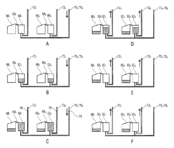
The fluidic module 50 shall be subjected, for example by the drive 20
described with
.. reference to Figs. 1 and 2, to a first rotational frequency fl in a first
phase (Figs. 4a to 4c),
while the fluidic module 50 is subjected to a second rotational frequency f2
in a second
phase (Figs. 4d to 4f). The second rotational frequency f2 is smaller than the
first rotational
frequency fl, f1 > f2.
Fig. 4a shows a schematic top view of the fluidic module 50 and a liquid level
within the
fluidic module 50 at a first point in time. At the first point in time, the
fluidic module 50 is
subjected to the first rotational frequency f1, whereby the liquid present,
e.g., within an
inlet area of the fluidic module 50 or is introduced into the inlet area of
the fluidic module
50 is centrifugally driven toward the measuring chambers 601 to 60, (n = 2)
via the fluid
inlet channels 701 to 70, (n = 2) connected, e.g., to the inlet area of the
fluidic module 50,
which results in the liquid level shown in Fig. 4a.
Fig. 4b shows a schematic top view of the fluidic module 50 and a liquid level
within the
fluidic module 50 at a second point in time. At the second point in time, the
fluidic module
.. 50 continues to be subjected to the first rotational frequency fl, whereby
the liquid is
centrifugally driven into the measuring chambers 601 to 60, (n = 2) via the
fluid inlet
channels 701 to 70, (n = 2), so that the liquid level within the measuring
chambers 601 to
60, (n = 2) has risen as compared to the liquid level shown in Fig. 4a.
.. In this process, as can be seen in Fig. 4b, the compressible medium
previously present
within the measuring chambers 601 to 60, (n = 2), within the fluid overflows
681 to 68, (n =
_
CA 02925839 2016-03-30
- 22 -
2) and within the compression chambers 621 to 62, (n = 2) is trapped and
compressed by
the liquid centrifugally driven into the measuring chambers 601 to 60, (n =
2), whereby a
pressure of the compressible medium rises. In other words, a volume that is
available to
the compressible medium is reduced by the liquid volume centrifugally driven
into the
measuring chambers 601 to 60, (n = 2), as a result of which the pressure of
the
compressible medium rises.
Fig. 4c shows a schematic top view of the fluidic module 50 and a liquid level
within the
fluidic module 50 at a third point in time. At the third point in time, the
fluidic module 50
continues to be subjected to the first rotational frequency f1, whereby the
liquid continues
to be centrifugally driven into the measuring chambers 601 to 60, (n = 2) via
the fluid inlet
channels 701 to 70,, so that by the third point in time, the liquid level
within the measuring
chambers 601 to 60, (n = 2) has risen up to the point of overflow and liquid
from the
measuring chambers 601 to 60, has got into the compression chambers 661 to 66,
(n = 2)
(n = 2) via the fluid overflows 681 to 68, (n = 2).
As compared to Fig. 4b, in Fig. 4c the volume available to the compressible
medium was
further reduced by the liquid volume centrifugally driven into the measuring
chambers 601
to 60, (n = 2) and now extends only to part of the compression chambers 661 to
66, (n =
2), which, with regard to Fig. 4b, results in a further increase in the
pressure of the
compressible medium.
Fig. 4d shows a schematic top view of the fluidic module 50 and a liquid level
within the
fluidic module 50 at a fourth point in time. Between the third and the fourth
points in time,
the rotational frequency to which the fluidic module 50 is subjected has been
reduced
from the first rotational frequency f1 to the second rotational frequency f2,
which results in
an expansion of the compressible medium, whereby the liquid present within the
measuring chambers 601 to 60, (n = 2) is driven out of the measuring chambers
601 to 60,
(n = 2) via the fluid outlet channels 721 to 72, (n = 2), while the liquid
that previously got
into the compression chambers 661 to 66, (n = 2) remains within the
compression
chambers 661 to 66, (n = 2).
Fig. 4e shows a schematic top view of the fluidic module 50 and a liquid level
within the
fluidic module 50 at a fifth point in time. At the fifth point in time, the
fluidic module 50
continues to be subjected to the second rotational frequency f2, whereby the
compressible
medium expands further, so that the liquid present within the measuring
chambers 601 to
. ,
CA 02925839 2016-03-30
- 23 -60. (n = 2) is (almost) completely driven out of the measuring chambers
601 to 60,, (n = 2)
via the fluid outlet channels 721 to 72, (n = 2).
Fig. 4f shows a schematic top view of the fluidic module 50 and a liquid level
present
within the fluidic module 50 at a sixth point in time. At the sixth point in
time, the fluidic
module 50 continues to be subjected to the second rotational frequency f2. Due
to the
liquid remaining within the compression chambers 661 to 66, (n = 2), the
compressible
medium expands further, so that the liquid cannot only be (almost) completely
driven out
of the measuring chambers 601 to 60, (n = 2) via the fluid outlet channels 721
to 72, (n =
2) but may even be (almost) completely driven into downstream chambers
connected with
the fluid outlet channels 721 to 72, (n = 2) (provided that a length of the
fluid outlet
channels 721 to 72, (n = 2) is configured accordingly).
In other words, due to the liquid volume remaining within the compression
chambers 661
to 66, (n = 2), the liquid volume metered within the measuring chambers 601 to
60, (n = 2)
may be (almost) completely driven, due to the expansion of the compressible
medium,
into downstream chambers connected to the fluid outlet channels 721 to 72, (n
= 2).
Thus, the fluidic module 50 as shown in Figs. 4a to 4f can be filled under
centrifugation
(see Fig. 4a). Once a first liquid volume has flowed into the measuring
chambers 601 to
60, (n = 2), the hermetically entrapped volume V of the compressible medium
(e.g., air
volume) will be compressed (see Fig. 4b). Any excess liquid flows from the
measuring
chambers 601 to 60r, (n = 2) into the compression chambers (e.g., collection
cavity) 661 to
66, (n = 2) via the fluid overflows 681 to 68, (n = 2) (see Fig. 4c). While
the rotational
frequency (rotational speed) is reduced, the compressible medium (e.g.,
entrapped air)
relaxes, and the liquid is forwarded into subsequent chambers through the
fluid outlet
channels 721 to 72, (n = 2) (see Figs. 4d and 4e). Due to the liquid remaining
within the
compression chambers 661 to 66, (n = 2), there will still be excess pressure
within the
compression chambers 661 to 66, (n = 2) even at the fifth point in time. This
results in that
even the liquid volume remaining within the fluid outlet channels 721 to 72,
(n = 2) can be
transported into subsequent chambers (or cavities).
Fig. 5 shows a schematic top view of a detail of a fluidic module 100 in
accordance with
an embodiment of the present invention. The fluidic module 50 shown in Fig. 5
comprises
eight measuring chambers 601 to 60, (n = 8) with associated compression
chambers 661
CA 02925839 2016-03-30
- 24 -
to 66, (n = 8), fluid overflows 681 to 68, (n = 8), fluid inlet channels 701
to 70, (n = 8) and
fluid outlet channels 721 to 72, (n = 8).
The eight measuring chambers 601 to 60, (n = 8) are subdivided into a first
half of
measuring chambers 601 to 604 and a second half of measuring chambers 605 to
608, the
first half of measuring chambers 601 to 604 being arranged radially further
inward than the
second half of measuring chambers 605 to 608.
The fluid inlet channels 701 to 704 of the first half of measuring chambers
601 to 604 are
connected to a first inlet area 841 of the fluidic module 50 via a first
manifold 801 and a first
radially extending channel 821, while the fluid inlet channels 705 to 708 of
the second half
of measuring chambers 605 to 608 are connected to a second inlet area 842 of
the fluidic
module 50 via a second manifold 802 and a second radially extending channel
822.
The fluid outlet channels 701 to 704 of the first half of measuring chambers
601 to 604 and
the fluid outlet channels 705 to 708 of the second half of measuring chambers
605 to 608
are connected in pairs, respectively, to a (downstream) chamber 861 to 864.
In detail, the first fluid outlet channel 721 and the fifth fluid outlet
channel 725 are
connected to the first (downstream) chamber 861, while the second fluid outlet
channel
722 and the sixth fluid outlet channel 726 are connected to the second
(downstream)
chamber 862, while the third fluid outlet channel 723 and the seventh fluid
outlet channel
727 are connected to the third (downstream) chamber 863 and while the fourth
fluid outlet
channel 724 and the eighth fluid outlet channel 728 are connected to the
fourth
(downstream) chamber 864.
For example, the fluidic module 50 may be used for mixing liquids in that a
first liquid is
introduced into the first inlet area 841 and a second liquid is introduced
into the second
inlet area 842, so that upon the reduction of the rotational frequency and the
associated
expansion of the compressible medium into the (downstream) chambers 861 to
864, an
aliquot of the first liquid and a aliquot of the second liquid are
centrifugally driven,
respectively.
In the following, the mode of operation of the fluidic module 50 shown in Fig.
5 will be
explained in more detail by means of Figs. 6a to 6e, which show liquid levels
within the
fluidic module 50 at five different points in time.
CA 02925839 2016-03-30
- 25 -
Fig. 6a shows a schematic top view of a partial detail of the fluidic module
50 and a liquid
level within the fluidic module 50 at a first point in time. At the first
point in time, the fluidic
module 50 is subjected to a first rotational frequency fl (e.g., f1= 90 Hz).
Fib. 6b shows a schematic top view of the partial detail of the fluidic module
50 and a
liquid level within the fluidic module 50 at a second point in time. At the
second point in
time, the fluidic module 50 continues to be subjected to the first rotational
frequency
whereby the liquid is centrifugally driven into the measuring chambers 601 to
604 via the
fluid inlet channels 701 to 704, which results in the liquid level shown in
Fig. 4h.
Fig. 6c shows a schematic top view of the partial detail of the fluidic module
50 and a
liquid level within the fluidic module 50 at a third point in time. At the
third point in time, the
liquid module 50 continues to be subjected to the first rotational frequency
f1, whereby the
liquid continues to be centrifugally driven into the measuring chambers 601 to
604 via the
fluid inlet channels 701 to 704, so that by the third point in time, liquid
has already got into
the compression chambers 661 to 664 from the measuring chambers 601 to 604 via
the
fluid overflows 681 to 684.
Fig. 6d shows a schematic top view of the partial detail of the fluidic module
50 and a
liquid level within the fluidic module 50 at a fourth point in time. Between
the third and
fourth points in time, the rotational frequency to which the fluidic module 50
is subjected
has been reduced from the first rotational frequency fl (e.g., f1 = 90 Hz) to
the second
rotational frequency f2 (e.g., f2 = 15 Hz), which leads to an expansion of the
compressible
medium, whereby the liquid present within the measuring chambers 601 to 604 is
driven
out of the measuring chambers 601 to 604 via the fluid outlet channels 721 to
724, while the
liquid that previously got into the compression chambers 661 to 664 remains
within the
compression chambers 661 to 664.
Fig. 6e shows a schematic top view of the partial detail of the fluidic module
50 and a
liquid level within the fluidic module 50 at a fifth point in time. At the
fifth point in time, the
fluidic module 50 continues to be subjected to the second rotational frequency
f2, whereby
the compressible medium has expanded to such an extent that the liquid present
within
the measuring chambers 601 to 60n (n = 2) has been (almost) completely driven
out of the
measuring chambers 601 to 604 via the fluid outlet channels 721 to 724.
CA 02925839 2016-03-30
- 26 -
In other words, Figs. 6a to 6d show an exemplary course of the aliquoting
process. Under
a high rotational frequency (centrifugation) of, e.g., 90 Hz, a first liquid
flows, via a
manifold 801, from an inlet area 841 into four measuring chambers 601 to 604
having a
volume of about 5 pl through a channel 821 leading radially outward.
The fluid inlet channel 701 to 704 leading to the measuring chamber 601 to 604
may be
configured to start at the top end of the measuring chamber 601 to 604 (not
mandatory).
The fluid outlet channel 721 to 724 is then hermetically sealed by a first
portion of the
inflowing liquid. Thus, further inflowing liquid will then (at least partly)
compress the
entrapped compressible medium (e.g., gas volume) within the compression
chamber
(pressure chamber) 661 to 664 (see Fig. 6b).
The liquid keeps on flowing until the inlet area 841 has been emptied
completely. Each of
the measuring chambers 601 to 604 has a compression chamber (pressure chamber)
661
to 664 connected to it wherein a defined volume of the compressible medium
(e.g., air
volume) is entrapped. Excess liquid keeps flowing into the drain areas of the
individual
compression chambers (pressure chambers) 661 to 664 until the inlet area 84,
has been
emptied (not mandatory). Now a balance between the centrifugal force and the
pneumatic
counter-pressure is achieved.
If the rotary frequency is reduced, the entrapped compressible medium (e.g.,
air volume)
within the compression chamber (pressure chamber 206) will expand under the
lower
centrifugal pressure. As a result, the liquid column within the radially
extending channel
821 and within the fluid outflow channel 721 to 724, which may be configured
as a siphon,
for example, increases in turn. From a specific fill height, the filling level
exceeds the crest
of the siphon 721 to 724, and the liquid is transported on. Due to the
centrifugal force and
excess pressure, the liquid is now completely transferred from the measuring
chambers
601 to 604 into the chambers 861 to 864.
Due to the fact that the fluid inlet channel (filling channel) 701 to 704
starts at the top end
of the measuring chamber 601 to 604, the liquid remains within the fluid inlet
channels 701
to 704 and is not distributed to the measuring chambers 601 to 604.
The accuracy of the aliquoting process will be particularly high when the
fluid inlet
channels 701 to 704 and the fluid outlet channels 721 to 724 are small as
compared to the
measuring chamber 601 to 604. Inaccuracies in measurement arise, e.g., due to
the fact
CA 02925839 2016-03-30
- 27 -
that different starting conditions such as the input volume, manufacturing
tolerances, etc.,
result in differences in the filling levels during the metering step. As a
result, the metering
accuracy is directly correlated to the dimensions of the fluid inlet channels
701 to 704 and
of the fluid outlet channels 721 to 724. In this context, smaller dimensions
will result in
more accurate metering.
Further measuring errors arise during emptying of the measuring chambers
(measuring
cavities) 601 to 604. Since there may be a difference in pressure between the
measuring
chambers 601 to 604, there may be an exchange of liquid between the measuring
chambers 601 to 604. To minimize this, it is possible, on the one hand, for
the fluid outlet
channel (e.g., siphon) 721 to 724 to have a fluidic resistance much smaller
than the sum of
resistances of the fluid inlet channels 701 to 704, and it is possible, on the
other hand, for
the fluid inlet channel (filling channel) 701 to 704 to start at a radially
inward point of the
measuring chamber 601 to 604. As a result, the measuring chambers 601 to 604
are not in
fluidic communication at least during a certain emptying period. During this
time, thus,
potential pressure differences will not cause any additional errors.
The above-described aliquoting concepts (radially inward aliquoting) may also
be used for
aliquoting liquids from radially outward to radially further inward by making
small changes
(radially outward aliquoting). In this context, the siphon 721 to 724 may be
replaced by a
fluid outlet channel 725 to 728 leading inward (see Fig. 5). The input volume
of the liquid
per measuring chamber (aliquoting chamber) 601 to 604 may be configured such
that
(virtually) all of the liquid present within the measuring chamber 601 to 604
and all of the
liquid present within the fluid outlet channel 725 to 728 is transferred into
a subsequent
chamber 861 to 864 located further inward.
By combining the two above-described aliquoting concepts (radially inward
aliquoting and
radially outward aliquoting), an aliquoting concept may be devised which
aliquots two
liquids on one fluidic layer. The overall structure may then be configured,
e.g., such that
an aliquot from a first aliquoting structure (first half of the measuring
chambers 601 to 604)
and an aliquot from a second aliquoting structure (second half of measuring
chambers 605
to 608), respectively are transferred into a shared chamber (cavity) 861 to
864. The
subsequent chamber (cavity) 861 to 864 may be a mixing chamber 86, to 864. The
entire
circumference around the axis of rotation may potentially be used for fluidic
structures.
CA 02925839 2016-03-30
- 28 -
The aliquoting concept presented herein generally is also suited for
aliquoting on a disc
structured in a multi-layered manner. The disc may be configured such that the
liquid for
filling may be guided over a fluidic layer A and in the process may
potentially be directed
past crossing channels. The chamber is now emptied via a channel on the
fluidic layer B.
This channel may be both a siphon (e.g., 721 to 724) and a different channel
leading
radially inward, for example (e.g., 725 to 728). Other than that, the
aliquoting process takes
place as was described with regard to radially inward aliquoting. This is the
obvious
process to be performed, e.g., when the number of aliquots for the radially
inward liquid is
high (> 10) and, as a result, the adjacently arranged siphon structures (721
to 724) can no
longer be introduced in a spatially efficient manner. Moreover, such a
configuration is
advantageous as soon as more than two liquids are aliquoted into one chamber
(cavity)
861 to 864. The fluidic connection may be realized either within the measuring
chamber
601 to 608 itself or within a fluidic opening specifically provided for this
purpose. It is
possible to either provide each measuring chamber 601 to 608 with a fluidic
opening of its
own or for several measuring chambers 601 to 608 to share one fluidic opening.
Embodiments of the present invention enable simultaneous, parallel aliquoting
of two
liquids on a fluidic layer. Measuring, or metering, of the volumes takes place
at high
pressures, whereby capillary forces have little influence. Moreover,
embodiments enable a
potentially high level of accuracy since metering of the liquids takes place
at high
rotational frequencies. In addition, embodiments require no sharp edges.
Unlike known aliquoting methods, the metering step of embodiments is performed
at
"high" rotational frequencies (rotary frequencies) and is subsequently
switched to low
rotational frequencies (rotary frequencies). Unlike known fluidic structures,
the fluidic
structure described herein is still functional even in the event of heavy
overfilling (> 50 %
of the volume measured). Unlike known aliquoting concepts, the aliquoting
concept
described herein enables aliquoting and connecting two liquids on one fluidic
layer. Unlike
known fluidic structures, in the fluidic structure described herein, the
liquid may be
supplied to the measuring chambers from outside and, additionally, the liquid
may
subsequently be processed further. Unlike known fluidic structures, at least
two aliquots
may have a waste cavity connected (directly or via a channel) to said metering
chamber,
which may be exploited, e.g., for performing individual quality control on
each single
aliquot by reading out the filling level within the waste cavity. Unlike known
fluidic
structures, in the fluidic structure described herein, the measuring chambers
are
=
CA 02925839 2016-03-30
- 29 -
separated from one another by a fluidic resistance higher than that of the
channel used for
forwarding the aliquots.
Further embodiments provide a fluidic structure comprising a fluid inlet
channel (fluid inlet)
having a high fluidic resistance, a fluid outlet channel (fluid outlet) having
a low fluidic
resistance, a measuring chamber and a compression chamber (pressure chamber),
which
are separated by a fluid overflow (fluid channel). The fluidic structure is
configured such
that upon filling of the fluidic structure, a compressible medium (e.g., air
volume) is
entrapped and that the volume of liquid introduced is larger than that
encompassed by the
volume of the measuring chamber, whereby excess liquid flows into the
compression
chamber (pressure chamber) through the fluid overflow and remains there; upon
reduction
of the rotational frequency (rotary frequency), a defined amount of liquid now
directed
through the fluid outlet channel (outlet).
Further embodiments provide a fluidic structure and a method of aliquoting
several
aliquots, the metering step being performed at "high" rotational frequencies
(rotary
frequencies), and forwarding of the liquids taking place at low rotary
frequencies. The
fluidic structure may be configured such that upon filling of the measuring
chamber, a
compressible medium (e.g., air) is compressed within the compression chamber.
Moreover, the fluidic structure may be configured such that the fluid inlet of
the measuring
chamber comprises a fluidic resistance higher than that of the fluid outlet of
the measuring
chamber. Furthermore, the fluidic structure may be configured such that at
least two
aliquots comprise a waste cavity connected (directly or via a channel) to said
measuring
chamber. In addition, the fluidic structure may be configured such that during
the volume-
determining metering step, the meniscus is present only in such channels which
are small
as compared to the measuring chamber. Moreover, the fluidic structure may be
configured
such that the volume-determining measuring chamber is filled to a level of
more than 50
% (70 A), 90 %, completely). Furthermore, the fluidic structure may be
configured such
that during emptying, an interface between the compressible medium and the
liquid (e.g.,
air/water interface) is displaced radially inward. Moreover, the fluidic
structure may be
configured such that at least one measuring chamber is filled from a radially
further inward
direction and is emptied in a radially further outward direction.
Fig. 7 shows a schematic top view of a detail of a fluidic module 100. The
fluidic module
100 includes a fluid inlet channel 102, at least one measuring chamber 1041 to
104;
comprising a fluid inlet 106i to 106; and a fluid outlet 1081 to 108, at least
one fluid
CA 02925839 2016-03-30
- 30 -
resistance element 1101 to 110; and an overflow 112, the fluid inlet channel
102 being
connected to the at least one measuring chamber 1041 to 104; via the fluid
inlet 1061 to
106; and to the overflow 112, and the at least one fluid resistance element
1101 to 110;
being connected to the at least one measuring chamber 1041 to 104; via the
fluid outlet
1081 to 108. The fluidic module 100 is configured such that upon rotation of
the fluidic
module about a center of rotation 114 and upon a centrifugal pressure
resulting therefrom,
a liquid is centrifugally driven into the at least one measuring chamber 1041
to 104, via the
fluid inlet channel 102, the at least one fluid resistance element 1101 to
1101 comprising a
fluidic resistance higher than a fluidic resistance of the fluid inlet channel
102 and than a
fluidic resistance of the fluid inlet 1041 to 104õ so that the volume of
liquid driven into the
at least one measuring chamber 1041 to 104, is larger than the volume of
liquid that exits
the at least one measuring chamber 1041 to 104; via the at least one fluid
resistance
element 1101 to 110, so that the at least one measuring chamber 1041 to 104;
is filled and
excess liquid gets into the overflow 112. The fluidic module 100 may further
be configured
such that upon an increase in the rotational frequency (e.g. by at least a
factor of 2 (or 3,
4, 5, 7, 10)) and upon an increase, resulting therefrom, of the centrifugal
pressure, the
liquid present within the at least one measuring chamber 1041 to 104, is
driven out of the
measuring chamber 1041 to 104, via the at least one variable fluid resistance
element 1101
- to 1101 faster than was the case prior to the increase in the rotational
frequency.
It shall be noted that the rotational frequency need not be increased in order
for the liquid
present within the at least one measuring chamber 1041 to 104, to be
centrifugally driven
out of same. The increase in the rotational frequency results in an increase
in the
centrifugal pressure, so that the liquid present within the at least one
measuring chamber
1041 to 104, can be driven out of same faster.
Moreover, the fluidic module 100 may comprise an inlet area 116 connected to
the fluid
inlet channel 102.
A first portion 102a of the fluid inlet channel 102 may be connected to the
inlet area 116
and may extend from radially further inward to radially further outward. A
second portion
102b of the fluid inlet channel 102, to which the at least one measuring
chamber 1041 to
104; may be connected, may extend laterally (e.g. have a uniform radial
distance from the
center of rotation 114). A third portion 102c of the fluid inlet channel 102
may extend from
radially further inward to radially further outward and may be connected to
the overflow
112.
CA 02925839 2016-03-30
- 31 -
Moreover, the fluidic module 100 may comprise at least one further chamber
1181 to 1184
connected to an output of the at least one variable fluid resistance element
1101 to 1101,
the at least one measuring chamber 1041 to 104; being connected to the at
least one
variable fluid resistance element 1101 to 110, via an input of the at least
one variable fluid
resistance element 1101 to 110i.
In other words, Fig. 7 shows a fluidic structure 100 (metering structure or
aliquoting
structure) comprising an inlet area 116, a filling and overflow channel 102, a
measuring
chamber 1041 to 104,, a valve 1101 to 1101 and an overflow 112, the valve 1101
to 110; not
closing completely but having liquid flow through it continuously.
In this context, the flow resistance of the valve 1101 to 1101 is sufficiently
high so that at a
first rotational frequency f1, the velocity at which the liquid fills the
measuring chamber
.. 1041 to 104, and at which excess liquid drains into the overflow area 112
from the inlet
area 116 via the overflow channel 102 is much higher than that at which liquid
is
forwarded into a subsequent chamber 1181 to 118; downstream from the valve
1101 to
1101. Typically, the process of dividing the liquid would be at least 10 times
(or, better, 100
times) faster than forwarding the liquid. As a result, the volume accuracy of
metering is
ensured without requiring a valve 1101 to 110; which would completely prevent
the flow of
liquid during the filling process.
Even though some aspects have been described within the context of a device,
it is
understood that said aspects also represent a description of the corresponding
method,
so that a block or a structural component of a device is also to be understood
as a
corresponding method step or as a feature of a method step. By analogy
therewith,
aspects that have been described in connection with or as a method step also
represent a
description of a corresponding block or detail or feature of a corresponding
device. Some
or all of the method steps may be performed by a hardware device (or while
using a
hardware device), such as a microprocessor, a programmable computer or an
electronic
circuit. In some embodiments, some or several of the most important method
steps may
be performed by such a device.
The above-described embodiments merely represent an illustration of the
principles of the
present invention. It is understood that other persons skilled in the art will
appreciate any
modifications and variations of the arrangements and details described herein.
This is why
- 32 -
the invention should not be limited to the specific embodiments presented
herein.
CA 2925839 2017-12-21