Note: Descriptions are shown in the official language in which they were submitted.
CA 02925865 2016-03-30
- 1 -
DESCRIPTION
Title of the Invention: IN-VEHICLE PICTURE STORAGE DEVICE FOR
MOTORCYCLE
Technical Field
[0001] The present invention relates to an in-vehicle video
storage device for a motorcycle that has a camera and a storage
device for storing pictures taken by the camera.
Background Art
[0002] There has been known an in-vehicle camera device
that has a camera unit capable of imaging the front side of a
vehicle body and a recording unit for recording pictures taken
by the camera unit as electronic data, and is mounted in a vehicle
so that the camera unit is secured to the front head portion
of a cowling with which the vehicle-body front portion of the
motorcycle is covered (see Patent Document 1, for example).
The camera unit is detachably mounted to the front head
portion of the cowling, and it may be detached from the front
head portion of the cowling to take pictures of a rider.
Prior Art Document
Patent Document
[0003] Patent Document 1: JP-A-2004-175126
Summary of the Invention
Problem to be solved by the Invention
[0004] In the Patent Document 1, images which are taken
by the camera unit and recorded in the recording unit can be
CA 02925865 2016-03-30
- 2 -
checked through a liquid crystal monitor. If the condition of
a vehicle or a rider can be viewed more realistically, it could
deepen an interest in the vehicle or the rider.
The present invention has been implemented in view of the
foregoing situation, and has an object to provide an in-vehicle
picture storage device for a motorcycle that a user can bodily
feel the condition of a vehicle or a rider more realistically.
Means of solving the Problem
[0005] In order to attain the above object, according to
the present invention, an in-vehicle picture storage device for
a motorcycle comprising a camera (111, 112) mounted in a vehicle,
and a storage device (113) for storing pictures taken by the
camera (111, 112), is characterized in that the camera (111,
112) contains a first camera (111) for imaging rider's facial
expression, and the storage device (113) stores vehicle
environmental information in association with pictures taken
by the first camera (111).
In the above construction, the vehicle environmental
information may be picture information in front of a vehicle.
[0006] In the above construction, the vehicle environmental
information may be position information from GPS (114).
In the above construction, the vehicle environmental
information may be vehicle speed information from ECU (116).
In the above construction, the vehicle environmental
information may be vehicle information containing throttle
CA 02925865 2016-03-30
- 3 -
opening, engine speed, etc.
[0007] In the above construction, the first camera (111)
and/or the second camera (112) may be disposed behind a wind
screen (30) that covers a meter group (31) disposed in front
of a handle (27) from the front side.
In the above construction, the back surface (30m) of the
wind screen (30) may be subjected to an irregular reflection
preventing treatment.
In the above construction, the first camera (111) may be
provided to be adjustable in angle.
[0008] In the above construction, the second camera (112)
may be provided to be near to the center in a vehicle width direction
of a stay (28, 144) provided to a head pipe (15) and proximate
to a headlight (29) for lighting the front side of a vehicle,
and the front surface of the second camera (112) is located behind
the headlight (29) .
In the above construction, the second camera (112) may
be fixed to the stay (28, 144) through a vibration absorber (241) .
Effect of the Invention
[0009] According to the present invention, the camera
contains the first camera for imaging the facial expression of
a rider, and the storage device stores the vehicle environmental
information in association with the pictures of the first camera.
Therefore, the pictures of the rider can be viewed while associated
with the vehicle environmental information. Accordingly, as
CA 02925865 2016-03-30
- 4 -
compared with a case where only the rider's pictures are viewed,
a user can bodily feel the conditions of the rider, the vehicle,
etc. more realistically. Therefore, the user's interest in the
rider, the vehicle, etc. can be more greatly deepened.
Furthermore, the vehicle environmental information is the
picture information in front of the vehicle which are taken by
the second camera. Therefore, by storing the motion and facial
expression of the rider in association with the picture
information in front of the vehicle, the condition of the rider
which is associated with the vehicle running region and the vehicle
running condition can be grasped from the associated information,
whereby the psychology of the rider under running can be guessed.
[0010] The vehicle
environmental information is the
position information from GPS . Therefore, by storing the rider's
motion and facial expression in association with the position
information of the vehicle, the variation and harsh condition
of the natural environments such as the weather, the temperature,
etc. which are associated with the vehicle position can be
recognized from the associated information.
Furthermore, the vehicle environmental information is the
vehicle speed information from ECU. Therefore, the by storing
the rider's motion and facial expression in association with
the vehicle speed information, the psychological state of the
rider which is appropriate to the vehicle speed can be guessed
from the associated information.
CA 02925865 2016-03-30
- 5 -
Furthermore, the vehicle environmental information is the
vehicle information such as the throttle opening, the engine
speed, etc. Therefore, by storing the rider's motion and facial
expression in association with the vehicle information, the
rider's psychology under acceleration/deceleration of the
vehicle or each engine load or at each engine speed can be guessed
from the associated information.
[0011] The first camera and/or the second camera is disposed
behind the wind screen which covers the meters disposed in front
of the handle from the front side. Therefore, the first camera
and/or the second camera can be protected from the front side
by the wind screen.
The back surface of the wind screen is subjected to the
irregular reflection preventing treatment. Therefore, light is
not irregularly reflected from the back surface of the wind screen,
and thus it can be prevented from being projected onto the pictures
of the first camera and the second camera.
The first camera is provided to be adjustable in angle.
Therefore, the rider ' s motion and facial expression can be easily
imaged by adjusting the angle (attitude) of the first camera.
[0012] Furthermore, the second camera is provided to be
near to the center in the vehicle width direction of the stay
provided to the head pipe and proximate to the headlight for
lighting the front side of the vehicle, and the front surface
of the second camera is located behind the headlight. Therefore,
CA 02925865 2016-03-30
- 6 -
the second camera can be disposed to be near to the center in
the vehicle width direction so that pictures of the second camera
can be made closer to the scenes in front of the vehicle. Still
furthermore, by providing the second camera in proximity to the
headlight, lighting for the second camera is unnecessary, and
the cost can be suppressed. Since the front surface of the second
camera is located behind the headlight, the light of the headlight
can be prevented from being projected onto the pictures of the
second camera.
Furthermore, the second camera is fixed to the stay through
the vibration absorber. Therefore, the vibration of the second
camera which is caused by the vibration of the vehicle is absorbed
by the vibration absorber, whereby pictures can be taken with
suppressing camera shake.
Brief Description of the Drawings
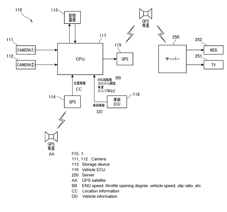
[0013] [Fig. 1] Fig. 1 is a block diagram showing an in-vehicle
picture storage deice according to a first embodiment of the
present invention.
[Fig. 2] Fig. 2 is a diagram showing a display example
in which various kinds of information stored in the in-vehicle
picture storage device is displayed on a display.
[Fig. 3] Fig. 3 is a right side view showing a motorcycle
in which the in-vehicle picture storage device is mounted.
[Fig. 4] Fig. 4 is a right side view showing the main part
of the vehicle body front portion of the motorcycle.
CA 02925865 2016-03-30
- 7 -
' [Fig. 5] Fig. 5 is a perspective view showing the
main
part of the vehicle body front portion of the motorcycle.
[Fig. 6] Fig. 6 is a right side view showing the main part
of a vehicle body front unit.
[Fig. 7] Fig. 7 is a back view of the main part of the
vehicle body front portion of the motorcycle.
[Fig. 8] Fig. 8 is a front view showing the main part of
the motorcycle under the state that a wind screen is detached.
[Fig. 9] Fig. 9 is a perspective view showing the main
part of the front portion of the motorcycle under the state that
the wind screen is detached.
[Fig. 10] Fig. 10 is a side view showing a mounting state
of a first camera.
[Fig. 11] Fig. 11 is a perspective view showing a mount
position of a second camera.
[Fig. 12] Fig. 12 is a perspective view showing a regulation
part and a support portion of a storage device.
[Fig. 13] Fig. 13 is a block diagram showing an in-vehicle
, picture storage device according to a second embodiment of the
present invention.
Mode for carrying out the Invention
[0014] Embodiments according to the present invention
will
be described hereunder with reference to the drawings.
<First Embodiment>
Fig. 1 is a block diagram showing an in-vehicle picture
CA 02925865 2016-03-30
- 8 -
storage device 110 according to a first embodiment.
The in-vehicle picture storage device 110 is mounted in
a motorcycle as a vehicle, and it is configured to contain two
cameras, a first camera 111 and a second camera 112, a storage
device 113, GPS 114, 115, a vehicle ECU 116 and CPU 117, a server
250, TV (Television) 251 and WEB (World Wide Web) 252.
The first camera 111 is a rider camera for imaging a rider
as an occupant of the motorcycle, and it images the motion of
a rider ' s upper body, rider's facial expression, etc., for example .
The second camera 112 is a front-view camera for imaging scenes
in front of the vehicle. The storage device 113 stores pictures
taken by the first camera 111 and the second camera 112,
environmental information of the vehicle, etc. as electronic
data, and a drive device for storing the electronic data into
a hard disc drive (HDD), a flash memory such as a flash disc
(SSD), a memory card or the like, a digital versatile disc (DVD),
a Blu-ray disc or the like is suitably usable as the storage
device 113.
[0015] GPS 114 is a
system for receiving signals from plural
GPS satellites and obtaining position information of the
motorcycle. GPS 115 is a system for transmitting the picture
information, the vehicle environmental information, etc. through
the GPS satellites to a server 250 (specifically, a receiver
provided to the server 250). The server 250 stores the picture
information, the vehicle environmental information, etc. into
CA 02925865 2016-03-30
- 9 -
a storage device thereof, and displays them on TV 251 or distributes
them to sites on WEB 252 through distribution servers contained
in WEB 252. TV 251 is suitable for domestic use or publicly
viewable.
Data transmission from the server 250 to TV 251 and WEB
252 is performed in wired and/or wireless communication style.
With respect to GPS 115, GPS 114 may be shared in place of GPS
115.
The vehicle ECU 116 is an engine control unit provided
to the motorcycle, and an engine speed (the number of revolutions
of the engine) , a throttle opening, a vehicle speed, wheel speeds
of front and rear wheels, etc. are input to the vehicle ECU 116
as signals from various sensors. CPU 117 is a central processing
unit for storing the picture information input from the first
camera 111 and the second camera 112, the position information
input from GPS 114 and the vehicle information such as the engine
speed, the throttle opening, the vehicle speed, a slip ratio
described below, etc. in the storage device 113 while the picture
information, the position information and the vehicle information
are associated with one another. CPU 117 calculates the slip
ratio of TCS (traction control system) on the basis of the wheel
speeds of the front and rear wheels described above.
Here, the picture information in front of the vehicle which
is obtained by the second camera 112, the position information
from GPS 114 and the vehicle information from the vehicle ECU
CA 02925865 2016-03-30
- 10 -
116 are information on an environment under which the vehicle
is placed and information of the vehicle itself, and it is called
as vehicle environmental information.
[0016] Fig. 2 is a diagram showing a display example in
which various kinds of information stored in the in-vehicle
picture storage device are displayed on a display 118.
The various kinds of information (electronic data) stored
in the storage device of the in-vehicle picture storage device
are displayed and available on the display 118.
The screen of the display 118 is divided into four parts.
Pictures in front of the vehicle (Front View 118A) which are
taken by the second camera 112 are displayed at the upper left
side, a rider's head portion (Rider View 118B) taken by the camera
111 is displayed at the lower left side, the engine speed (Ne),
the throttle opening (Th), the vehicle speed (V) and the slip
ratio (TCS) as the vehicle information (Vehicle Information 118C)
are displayed at the upper right side while arranged together
with the date (DATE) and hour (TIME) at which the pictures of
the first camera 111 and the second camera 112 are taken, and
a map (Map 118D) is displayed at the lower right side. The
direction to North (N) and the present position of the motorcycle
(blacked triangle) are displayed on the map.
[0017] The Front View 118A, the Rider View 118B and the
Vehicle Information 118C and the Map 118D are taken at the same
hour on the same date, and they are associated with one another
CA 02925865 2016-03-30
- 11 -
with respect to the time.
As described above, according to this embodiment, the
various kinds of information are displayed in association with
the time. Therefore, when a condition under which the motorcycle
runs is afterwards displayed on the display 118, a user (the
rider) can experience the condition concernedmore realistically.
When the in-vehicle picture storage device 110 is provided
with GPS 115 as shown in Fig 1, the picture information, the
vehicle environmental information, etc. can be transmitted to
other servers so that the condition of the motorcycle is
individually enjoyed, and further displayed on the publicly
viewable TV 251 or uploaded to WEB 252 (WEB site) to make many
people enjoy the condition of the motorcycle.
[0018] Fig. 3 is a
right side view showing the motorcycle
1 in which the in-vehicle picture storage deice 110 is mounted.
In the following description, the descriptions on front-and-rear,
right-and-left and up-and-down directions are the same as the
directions of the vehicle body if not specifically described.
Furthermore, character FR represented in the figures represents
the forward direction of the vehicle body, character UP represents
the upward direction of the vehicle body and character LE
represents the leftward direction of the vehicle body.
The motorcycle 1 is a vehicle for rally competition in
which an engine 50 as a power unit is supported by a vehicle
body frame F, a front fork 10 supporting a front wheel 2 is steerably
CA 02925865 2016-03-30
- 12 -
supported at the front end of the vehicle body frame F and a
swing arm 11 supporting a rear wheel 3 is provided to the rear
portion of the vehicle body frame F.
Furthermore, the motorcycle 1 is also a saddle-type vehicle
in which a seat 12 on which a rider straddles and sits is provided
at the upper side of the center portion in the front-and-rear
direction of the vehicle body frame F. Furthermore, the
motorcycle 1 is an off-road type vehicle suitable for running
on an irregular ground such as a sandy place or the like, and
it has a large suspension stroke and is provided with a large-size
fuel tank 40.
[0019] The vehicle body frame F is configured to have a
front frame 13 which is formed like a basket by joining pipe
members and plate members through welding or the like, and a
rear frame 14 which is connected to the rear portion of the front
frame 13 and formed of resin.
The front frame 13 has a head pipe 15 (see Fig. 4) provided
to the front end, a pair of right and left main frames 16 which
extend from the head pipe 15 backwards while sloping obliquely
downwards, and a pair of right and left pivot frames 17 extending
downwards from the respective rear ends of the main frames 16.
A pivot shaft 24 for supporting the front end portion of
the swing arm 11 freely swingably is provided to the lower portion
of the pivot frame 17.
[0020] A cylindrical rear suspension unit 26 is disposed
CA 02925865 2016-03-30
- 13 -
to be tilted forwards so that the upper end thereof is connected
to the upper portion of the front frame 13 and the lower end
thereof is connected to the swing arm 11 through a link mechanism
(not shown).
The front fork 10 is supported through a steering shaft
(not shown) by the head pipe 15 to be freely turnable, and the
front wheel 2 is pivotally supported by the lower end of the
front fork 10. A steering handle 27 is fixed to the upper end
of the front fork 10.
A front stay 28 projecting forwards is fixed to the front
portion of the head pipe 15, and a headlight 29, a wind screen
30 and a meter group 31 are supported on the front stay 28.
A fuel tank 40 has a pair of right and left front tanks
41, 42 (only the front tank 42 at the right side in Fig. 3 is
illustrated) which are disposed divisionally at the right and
left sides of the right and left main frames 16, and a rear tank
43 provided on the rear frame 14.
The seat 12 extends backwards to be continuous with the
rear portions of the front tanks 41, 42, and is supported by
the upper portion of the rear frame 14.
[0021] The
motorcycle has a vehicle body cover 32 formed
of resin. The vehicle body cover 32 has a pair of right and left
shrouds 33 which cover, from both the sides, the upper portion
of the front fork 10 and a down frame (not shown) extending
substantially downwards from the head pipe 15, a tank cover 34
CA 02925865 2016-03-30
- 14 -
covering the front tanks 41, 42 from the upper side, an under
cover 35 covering the lower portion of the front frame 13 and
a crankcase 52 of the engine 50 from the upper side and the lower
side, and a pair of right and left fork covers 36L, 36R (only
the fork cover 36R at the right side is illustrated) covering
the lower portion of the front fork 10.
A front fender 37 covering the front wheel 2 from the upper
side is fixed to the front fork 10. A rear fender 38 covering
the rear wheel 3 from the upper side is fixed to the rear frame
14 behind the seat 12.
A pair of right and left steps 39 on which the rider puts
his/her feet are provided to the lower ends of.the right and
left pivot frames 17. A shift pedal (not shown) is provided in
front of the left-side step 39, and a brake pedal 45 is provided
in front of the right-side step 39.
[0022] The engine 50 is a water cooling type single-cylinder
four-cycle engine, and supported in the basket-shaped front frame
13. A crankshaft (not shown) of the engine 50 is disposed to
extend horizontally in the vehicle width direction. The engine
50 has the crankcase 52, and a cylinder portion (not shown)
projecting upwards from the upper surface of the front portion
of the crankcase 52.
[0023] An exhaust pipe 66 of the engine 50 extends frontwards
and downwards from the front surface of the cylinder head (not
shown) provided to the cylinder portion, and then is drawn to
CA 02925865 2016-03-30
- 15 -
the right side . Furthermore, the exhaust pipe 6 extends backwards
along the lower portion of the front frame 13, and is connected
to a muffler 67 disposed at the right side of the rear wheel
3. The muffler 67 is supported by the rear frame 14.
A pair of radiators 68L, 68R (only the radiator 68R at
the right side is illustrated) in which cooling water of the
engine 50 is circulated are provided among the down frame (not
shown) constituting the front frame 13 and the right and left
shrouds 33.
The front tanks 41, 42 are configured to have such a size
that they extend among the right and left shrouds 33 and the
rear frame 14, extend downwards from the outsides of the right
and left main frames 16 and cover the cylinder portion and the
side of the front portion of the crankcase 52.
The rear frame 14 is provided with vehicle ECU 116 as a
controller of the motorcycle 1. Amudguard 80 extending downwards
to the front side of the rear wheel 3 is secured to the lower
portion of the rear frame 14.
[0024] Fig. 4 is a
right side view showing the main part
of the vehicle body front portion of the motorcycle 1.
The vehicle body front unit 100 in which the headlight
29, the wind screen 30, the meter group 31, other electrical
components, etc. are mounted is secured to the head pipe 15.
The vehicle body front unit 100 has a front stay 28 which
is freely detachably secured to the front portion of the head
CA 02925865 2016-03-30
- 16 -
pipe 15 with plural screws, and the respective parts are secured
to the front stay 28 directly or through plural stays.
The wind screen 30 is transparent, and is located distantly
ahead of the handle 27 so as to cover the meter group 31, etc.
from the front side. The center portion in the longitudinal
direction of the wind screen 30 is located substantially at the
same height as grips 27a, 27b (only the grip 27a at the right
side is illustrated) of the handle 27 under the state that the
front wheel 2 (see Fig. 1) is oriented to face the straight forward
direction.
[0025] The shroud 33 is configured so that the neighborhood
of the tip portion 33a thereof is detachably secured to the lower
portion of the vehicle body front unit 100, and the neighborhood
of the rear end portion 33b of the upper portion thereof is
detachably secured to the front-side tanks 41, 42 (only the front
tank 42 at the right side is illustrated) through the stay.
Each of the right and left shrouds 33 is disposed at a
lower position than the support member 102 of the handle 27 provided
to the upper portion of the front fork 10, and the tip portion
33a of the shroud 33 and the lower end portion 30a of the wind
screen 30 are separated from each other in the up-and-down
direction.
[0026] The support member 102 of the handle 27 is fixed
to the upper portion of a top bridge 122 for connecting the right
and left sides of the front fork 10. A steering damper 123 for
CA 02925865 2016-03-30
- 17 -
moderating rapid turning of the handle 27 caused by external
force is bridged between the top bridge 122 and the front frame
13 (see Fig. 3).
In side view, both the sides of a space 125 surrounded
by the wind screen 30 and the shrouds 33 are opened, and a harness
connector 126 for electrical components which is secured to the
right side portion of the front stay 28 is exposed upwards and
sideward. Accordingly, a main harness connecting terminal 154,
connection connectors of respective electrical components (not
shown), etc. can be easily connected to and disconnected from
the harness connector 126. Furthermore, the screws with which
the front stay 28 is fixed to the head pipe 15 are loosened,
the main harness connecting terminal 154 is detached from the
harness connector 12 for electrical components, and harnesses
of some electrical components connected to the harness connector
126 for electrical components are detached, whereby the vehicle
body front unit 100 can be easily detached from the vehicle body .
[0027] Fig. 5 is a
perspective view showing the main part
of the vehicle body front portion of the motorcycle 1.
The front side of the vehicle front unit 100 constructed
by the headlight 29, the meter group 31, the first camera 11,
the second camera 112, a GPS antenna 156 for reception and
transmission, etc. is covered by the transparent wind screen
30.
The headlight 29 comprises a first light 216 containing
CA 02925865 2016-03-30
- 18 -
LEDs as a light source, and a second light 217 containing a bulb
as a light source.
The wind screen 30 is designed in a curved shape so that
the center in the vehicle width direction thereof is convex
forwards, and rear end portions 30b, 30b which project to the
most backward position are provided substantially at the center
in the height direction.
Furthermore, the wind screen 30 is also designed in an
vertically long arcuate shape so that the upper edge thereof
is convex upwards. The lower portion of the wind screen 30 has
a vertically long portion which gradually narrows to the lower
portion thereof, and integrally extends sideward from the lower
portion of the vertically long portion.
Fixing portions 30f, 30g, 30g for fixing the wind screen
30 to the parts constituting the vehicle body front unit 100
are provided to the lower portion at the center in the vehicle
width direction of the vertically long portion and in the
neighborhood of the rear end portions 30b, 30b.
The first camera 111 is disposed above the meter group
31. The second camera 112 is disposed to be adjacent to the
headlight 29. The GPS antenna 156 for reception and transmission
constitutes a part of GPS 114 (see Fig. 1), and disposed below
the first camera 111 and above the headlight 29 and the second
camera 112.
[0028] Fig. 6 is a
right side view showing the main part
CA 02925865 2016-03-30
- 19 -
of the vehicle body front unit 100.
To the front stay 28 are secured a road book holder stay
142 for supporting a road book holder 141, a headlight stay 144
for supporting the headlight 29, and an oil cooler stay 147 for
supporting an oil cooler 146.
The road book holder 141 is a device that holds a road
book comprising plural maps describing the distance from a start
point, etc. in a rally competition, and is capable of performing
page ejection by take-up.
[0029] The harness
connector 126 for electrical components
and a horn 151 are directly secured to the side surface of the
front stay 28. The harness connector 126 for electrical
components is provided with amain harness receiving connector
152 and plural electrical-component receiving connectors 153.
The main harness receiving connector 152 is provided to the lower
end surface of the harness connector 126 for electrical components,
and a main harness connection terminal 154 provided to the end
portion of a main harness 150 is connected to the main harness
receiving connector 152. The plural electrical-component
receiving connectors 153 are provided to the side surface of
the harness connector 126 for electrical components.
A connection terminal 155 provided to the end portions
of harnesses 159 (only one harness 159 is illustrated) extending
from the road book holder 141, the headlight 29, the horn 151,
a fuse box 158, a dimmer switch 171 (see Fig. 7), a vehicle speed
CA 02925865 2016-03-30
- 20 -
sensor for the front wheel, etc. are connected as the electrical
components disposed in the vehicle body front unit 100 to the
plural electrical-component receiving connectors 153.
[0030] The GPS
antenna 156 for reception and transmission,
an auxiliary trip meter 157 and the fuse box 158 are secured
to the road book holder stay 142. The auxiliary trip meter 157
is used subsidiarily for a main trip meter described later in
detail or when the main trip meter 167 is not operable, and it
can display the vehicle speed.
The second camera 112 for imaging the front side of the
vehicle body of the running vehicle and the wind screen 30 are
secured to the headlight stay 144. The back surface 30m of the
wind screen 30 is subjected to an irregular reflection preventing
treatment for preventing light, particularly light of the
headlight 29 from being irregularly reflected from the back
surface 30m and projected into pictures of the second camera
112. Coating of irregular reflection preventing paint or
attachment of irregular reflection preventing film may be
performed as the irregular reflection preventing treatment.
A buzzer 163 and the wind screen 30 are secured to the
oil cooler stay 147. The buzzer 163 is a regulation part delivered
from an organizer of the competition, and it is operated to ring
by the organizer.
[0031]
Fig. 7 is a back view showing the main part of the front
CA 02925865 2016-03-30
- 21 -
portion of the vehicle body of the motorcycle.
The road book holder 141 has an actuator 166 for taking
up the road book. The main trip meter 167 is disposed at the
upper left side of the road book holder 141. Furthermore, an
information meter 168 for displaying the residual amount of fuel
and the mode of TCS is disposed at the upper side of the main
trip meter 167. An electronic compass 169 is disposed at the
upper right side of the load book holder 141. The electronic
compass displays the vehicle speed, the azimuth direction (travel
direction) and the distance from the start point of the motorcycle
which are obtained by the GPS antenna 156 for reception and
transmission (see Fig. 6).
The main trip meter 167, the information meter 168, the
electronic compass 169 and the auxiliary trip meter 157 are
contained in the meter group 31.
The first camera 111 is disposed on the upper surface of
the main trip meter 167 and at the side of the information meter
168.
[0032] A dimmer
switch 171 for switching the headlight 29
between a high-beam mode and a low-beam mode (see Fig. 6) is
secured to the left lower end portion of the road book holder
stay 142.
The headlight stay 144 has a screen support unit 144a
extending in the vehicle width direction, and the right and left
fixing portions 30g, 30g (see Fig. 5) of the wind screen 30 are
CA 02925865 2016-03-30
- 22 -
secured to the screen fixing portions 144b, 144b provided to
both the ends of the screen support unit 144a by screws.
[0033] Amulti-operation switch 175 for the road book holder
141 and the main trip meter 167, an engine operating switch 176
and a horn switch 177 for the horn 151 (see Fig. 6) are secured
to the handle 27 in the neighborhood of the let-side grip 27b.
The multi-operation switch 175 has a mode switching button
181 for the main trip meter 167, error adjusting buttons 182,
183 for the main trip meter 167, and an actuator operating switch
184 for operating the actuator 166 of the road book holder 141
to take up the road book. The mode switch button 181 is a button
for switching the display mode among the running distance, the
vehicle speed and the clock. The error adjusting buttons 182,
183 advance or turn back the distance displayed on the main trip
meter 167 to adjust the error between the distance indicated
on a road map and the distance of the main trip meter 167.
[0034] The engine operating switch 176 has a map switching
button 185 for switching a control map stored in a memory of
ECU 78 (see Fig. 3) to control the engine. The horn switch 177
has a headlight indicator 187 which is provided in the neighborhood
of the horn button 186 and turned out when the headlight 29 is
set to the high beam.
A main switch 191 and a starter switch are secured to the
handle 27 in the neighborhood of the right-side grip 27a. The
starter switch 192 has a starter button 194, and an Fl indicator
CA 02925865 2016-03-30
- 23 -
195 which lights to notify abnormality of a fuel injection system
of the engine and reduction of a battery voltage.
[0035] Fig. 8 is a front view showing the main part of the
motorcycle 1 under the state that the wind screen is detached.
The GPS antenna 156 for reception and transmission
comprises plural antenna bodies 211, 212, 213, and these antennas
bodies are secured and arranged in the vehicle width direction
on a seat portion 215 which is provided to the road book holder
stay 142 so as to project forwards. The antenna body 211 is
exclusively used for transmission, the antenna body 212 is
exclusively used for reception, and the antenna body 213 is used
for both reception and transmission.
A first light 216 constituting the headlight 29 is disposed
substantially at the center in the vehicle width direction, a
second light 217 is disposed at the upper right side of the first
light 216 and the second camera 112 is disposed below the second
light 217. When the headlight 29 is set to the low beam, only
the first light 216 is turned on. When the headlight 29 is set
to the high beam, both the first light 216 and the second light
217 are turned on.
[0036] Fig. 9 is a perspective view showing the main part
of the front portion of the motorcycle 1 under the state that
the wind screen is detached.
The oil cooler stay 147 has a pair of upper and lower forward
projecting portions 147a and 147b, cross portions 147c, 147c
CA 02925865 2016-03-30
- 24 -
and end portion connecting portions 147d, 147d.
The forward proj ecting portions 147a, 14 7b proj ect forward,
and the cross portions 147c, 147c extend from the intermediate
portions of the forward projecting portions 147a, 147b in the
vehicle width direction. The end portion connecting portions
147d, 147d connect both the end portions of the cross portions
147c, 147c, andhave a pair of right and left shroud fixingportions
147e, 147e to which the tip portions 33a of the shrouds 33 (see
Fig. 4) are fixed. Reference numeral 148 represents a screw for
fastening the tip portion of the shroud 33 to the shroud fixing
portion 147e. The oil cooler 147 is secured to the forward
projecting portions 147a, 147b. Reference numerals 146a, 146a
represent hose fixing ports for supplying and exhausting oil
in the oil cooler 146.
For example, a regulation part (a distress beacon emitting
device) 221 delivered from the organizer of the competition is
disposed behind the first light 216 of the headlight 29 and the
oil cooler 146. A storage device 113 containing CPU 117 (see
Fig. 1) is secured to a side surface of the regulation part 221.
[0037] Fig. 10 is a
side view showing the mount state of
the first camera 111. In Fig. 10, the electronic compass (see
Fig. 9) is detached from the road book holder stay 142.
A seat-like vibration absorber 231 is attached to the upper
surface 167a of the main trip meter 167, a camera bracket 233
having a substantially U-shaped cross-section is attached to
CA 02925865 2016-03-30
- 25 -
the upper surface of the vibration absorber 231, and the first
camera 111 is secured to the camera bracket 23 through a bolt-like
support shaft 234 so as to be swingable in the up-and-down direction .
Reference numeral 236 represents a camera mount piece which is
secured to the lower portion of the first camera 111 and is
supported through the support shaft 234.
The first camera 111 is adjusted in angle to be tilted
forwards and upwards so that the rider, particularly, the rider's
upper half body or face can be imaged by the first camera 111.
The angle adjustment is performed by loosening the support shaft
234 relatively to the nut provided to the camera mount piece
236 and swinging the first camera 111 in the up-and-down direction
(specifically, in the direction of an arrow in Fig. 10) . After
the angle adjustment, the support shaft 234 is fastened to fix
the angle of the first camera 111.
[0038] As shown in
Figs. 7 and 10, the first camera 111
is disposed on the upper portion of the main trip meter 167 which
is required to be checked at all times under running of the vehicle,
and also disposed in the neighborhood of the information meter
168 and the electronic compass 169 which are likewise required
to be checked at all times, so that rider's facial expression
and motion can be excellently imaged by the first camera 111
without paying rider's attention to the first camera 111 when
the rider directs his/her face or eye line to the respective
kinds of meters.
CA 02925865 2016-03-30
- 26 -
[0039] Fig. 11 is a perspective view showing the mount
position of the second camera 112.
A light bracket 238 having a substantially U-shaped
cross-section for supporting the second light 217 (see Fig. 9)
is secured to the upper portion of the right side surface 144c
of the headlight stay 144 so as to be located below the screen
support portion 144a extending in the right-and-left direction.
A vibration absorber 241 is secured to the right side surface
144c so as to be located below the light bracket 238, and the
second camera 112 is freely detachably secured to the vibration
absorber 241 through a hook-and-loop fastener (touch fastener)
242.
[0040] The vibration absorber 241 is of a low repulsion
type having a high vibration/impact absorbing property, and it
prevents vibration or impact occurring in the vehicle body from
being transmitted to the second camera 112, whereby camera shake
can be suppressed and high-quality camera pictures can be
obtained.
The hook-and-loop fastener 242 comprises a coupled portion
244 attached to the vibration absorber 241, and a coupling portion
245 which is attached to the base portion 112a of the second
camera 112 so as to be detachably coupled to the coupled portion
244. For example, the hook-and-loop fastener 242 comprises an
endless number of coupled pieces and an endless number of coupling
pieces to be coupled to the coupled pieces as if an endless number
CA 02925865 2016-03-30
- 27 -
of hooks and an endless number of loops are coupled to one another,
one of the coupled piece group and the coupling piece group is
providedto the coupledportion 244 , and the othergroup is provided
to the coupling portion 245.
[0041] Fig. 12 is a perspective view showing a support
portion for the regulation part 221 and the storage device 113.
A side bracket 247 is secured to the left side of the oil
cooler stay 147, the regulation part 221 is secured to the side
bracket 247, and the storage device 113 is secured to the side
surface of the regulation part 221. The regulation part 221 is
disposed so as to occupy a large space at the left side of the
front stay 28 and the oil cooler stay 147 of the vehicle front
unit 100 (see Fig. 4). A large-size side bracket 247 is used
to support the storage device 113 and the large-size regulation
part 221.
Since the storage device 113 is secured to the regulation
part 221, another wire can be easily branched from various signal
wires to be connected to the regulation part 221 to the storage
device 113 to receive signals, so that the wires can be shortened
and the wiring work can be efficiently performed.
[0042] As shown in Figs. land 2, in the in-vehicle picture
storage device 110 for the motorcycle having the camera (the
first camera 111 and the second camera 112) mounted in the vehicle
body and the storage device 113 for storing pictures taken by
the camera (the first camera 111 and the second camera 112),
CA 02925865 2016-03-30
- 28 -
the camera contains the first camera 111 for imaging the rider's
facial expression, and the storage device 113 stores the vehicle
environmental information in association with the pictures of
the first camera 111.
According to this construction, since the camera contains
the first camera 111 for imaging the rider's facial expression,
and the storage device 113 stores the vehicle environmental
information in association with the pictures of the first camera
111, the rider's motion and facial expression are imaged by the
first camera 111, and the pickup pictures are stored in association
with the vehicle environmental information, so that the rider's
pictures can be viewed in association with the vehicle
environmental information. Accordingly, a user can experience
(bodily feel) the conditions of the rider, the vehicle, etc.
more realistically as compared with a case where only the pictures
of the rider are merely viewed. Therefore, the interest in the
rider, the vehicle, etc. (the vehicle body itself, and
environments such as scenes and geography of a region where the
vehicle runs, animals and plants living in the region, etc.)
can be more deepened.
Furthermore, the vehicle environmental information
contains the picture information in front of the vehicle which
is taken by the second camera 112. Therefore, by storing the
rider's motion and facial expression in association with the
picture information in front of the vehicle, the vehicle running
CA 02925865 2016-03-30
- 29 -
region and the rider' s state corresponding to the vehicle running
state can be grasped on the basis of the associated information.
Accordingly, for example, rider's psychology under vehicle
running can be guessed.
[0043] Furthermore,
the vehicle environmental information
contains the position information from GPS 114. Therefore, by
storing the rider's motion and facial expression in association
with the position information of the vehicle, variation and harsh
condition of the natural environment such as weather, temperature,
etc. which correspond to the vehicle position, for example, can
be recognized from the associated information.
Furthermore, the vehicle environmental information
contains the vehicle speed information from ECU 116. Therefore,
by storing the rider' s motion and facial expression in association
with the vehicle speed information, the rider's psychological
state appropriate to the vehicle speed, for example, can be guessed
from the associated information.
Still furthermore, the vehicle environmental information
contains the vehicle information such as the throttle opening
th, the engine speed Ne, the slip ratio of TCS, etc. Therefore,
by storing the rider ' s motion and facial expression in association
with the vehicle information, the rider's psychology under
acceleration/deceleration of the vehicle or each engine load
or at each engine speed, for example, can be guessed from the
associated information.
CA 02925865 2016-03-30
- 30 -
[0044] As shown in Fig. 5, the first camera 111 and/or the
second camera 112 are/is disposed behind the wind screen 30 which
covers the meter group 31 as measuring gauges disposed in front
of the handle 27. Therefore, the first camera 111 and/or the
second camera 112 can be protected from the front side by the
wind screen 30.
As shown in Fig. 6, the back surface 30m of the wind screen
30 is subjected to the irregular reflection preventing treatment.
Therefore, light is not irregularly reflected from the back
surface 30m of the wind screen 30, and thus it can be prevented
from being projected into pictures of the first camera 111 and
the second camera 112.
As shown in Fig. 10, the first camera 111 is provided so
that the angle thereof can be adjusted, so that the rider's motion
and facial expression can be made to be easily imaged by adjusting
the angle of the first camera 111.
[0045] As shown in Figs. 4, 6 and 8, the second camera 112
is provided in proximity to the front stay 28 as a stay provided
to the head pipe 15 and the headlight 29 which is near to the
center in the vehicle width direction of the headlight stay 144
and lights the front side of the vehicle, and the front surface
of the second camera 112 is located behind the headlight 29,
so that the second camera 112 can be disposed to be near to the
center in the vehicle width direction and pictures of the second
camera 112 can be made closer to scenes in front of the vehicle
CA 02925865 2016-03-30
- 31 -
which are viewed by the rider. Furthermore, by providing the
second camera 112 in proximity to the headlight 29, lighting
for the second camera 112 is unnecessary, and thus the cost can
be suppressed. Since the front surface of the second camera
112 is located behind the headlight 29, the light of the headlight
29 can be prevented from being projected into the pictures of
the second camera 112.
As shown in Fig. 11, the second camera 112 is fixed to
the front stay 28 and the headlight stay 144, specifically, to
the right side surface 144c of the headlight stay 144 through
the vibration absorber 241. Therefore, vibration of the second
camera 112 which follows vibration of the vehicle body can be
absorbed by the vibration absorber 241, so that pictures can
be taken while suppressing camera shake.
[0046] <Second Embodiment>
Fig. 13 is a block diagram showing an in-vehicle picture
storage device 300 according to a second embodiment of the present
invention. The same constituent elements as the first
embodiment are represented by the same reference numerals, and
the detailed description thereof is omitted.
The in-vehicle picture storage device 300 is mounted in
a motorcycle as a vehicle. In the in-vehicle picture storage
device 300, a microphone 301 and an in-vehicle monitor 302 are
added to the in-vehicle picture storage device 110 of the first
embodiment shown in Fig. 1.
CA 02925865 2016-03-30
- 32 -
The microphone 301 converts surrounding sounds and rider ' s
voices under running or stop of the motorcycle to electrical
signals. The electrical signals are stored in the storage device
113 by CPU 117 while associated with the picture information
from the first camera 111 and the second camera 112, the position
information from GPS 114 and the vehicle information from the
vehicle ECU 116.
The in-vehicle monitor 302 is capable of displaying
pictures being taken by the first camera 111 and the second camera
112 or pictures stored in the storage device 113. The pictures
taken by both the first camera 111 and the second camera 112
can be displayed at the same time or only the pictures taken
by one of these cameras may be displayed on the in-vehicle monitor
302.
The sound/voice information obtained by the microphone
301 is one of the vehicle environmental information.
[0047] The
embodiments described above are examples of the
present invention, and any modification and application may be
made without departing from the subject matter of the present
invention.
For example, in the above embodiments, the first camera
111 is secured to the upper surface of the main trip meter 167
as shown in Fig. 7. However, the present invention is not limited
to this style, and the first camera 111 may be secured to the
upper surface of the electronic compass 169.
CA 02925865 2016-03-30
- 33 -
Furthermore, as shown in Fig. 10, the first camera 111
is secured to the upper surface of the main trip meter 167 through
the vibration absorber 231. However, the present invention is
not limited to this style, and the first camera 111 may be
detachably secured through a hook-and-loop faster 242 as shown
in Fig. 11 to the vibration absorber 231 which is secured to
the upper surface of the main trip meter 167.
Still furthermore, as shown in Figs . 1 and 5 , the two cameras
of the first camera 111 and the second camera 112 are provided
to the in-vehicle picture storage device 110. However, the
present invention is not limited to this style, and a camera(s)
for taking scenes around the vehicle such as scenes of the side (s)
of the vehicle, the back side of the vehicle or the like may
be provided in addition to the above two cameras.
Description of Reference Numerals
[0048] 1 motorcycle
15 head pipe
27 handle
28 front stay (stay)
29 headlight
30 wind screen
30m back surface
31 meter group (measuring gauge)
110 in-vehicle picture storage device
111 first camera
CA 02925865 2016-03-30
- 34 -
112 second camera
113 storage device
114 GPS
116 vehicle ECU (ECU)
144 headlight stay (stay)
241 vibration absorber