Note: Descriptions are shown in the official language in which they were submitted.
LOW PROFILE ELECTRICAL TERMINAL ASSEMBLY
CROSS REFERENCE TO RELATED APPLICATION
[0001] The present application claims the benefit of U.S. provisional
application Ser. No.
62/143,930, filed Apr. 7, 2015.
FIELD OF THE INVENTION
[0002] The present invention relates to electrical power systems for use in
work areas and, more
particularly, to electrical terminals for use in modular electrical systems.
BACKGROUND OF THE INVENTION
[0003] Modular electrical power systems are typically used in office areas and
other work areas
or places where access to electrical power is desirable, and particularly in
flexible areas that arc
designed to be reconfigurable to suit changing needs, such as with movable
partition walls and
other furnishings. In some cases, it is desirable to set up electrical power
systems in exposed
locations, such as along floors or walls, in which case it may be particularly
desirable to use
electrical conduits and connectors that have very low overall thickness,
especially when used in
walking areas.
SUMMARY OF THE INVENTION
[0004] The present invention provides a low profile electrical terminal
assembly, such as for use
in a junction of a modular electrical system, in which a plurality of
electrical terminals are
arranged in generally the same plane (i.e., arranged between two substantially
parallel planes that
are in close proximity), and that permit the establishment of electrical
connections. The low
profile electrical terminal assembly is particularly well adapted for routing
power in different
directions from a junction point in a modular electrical system, and has a
very thin or minimally
intrusive thickness. The assembly includes at least two conductive main bodies
that are stacked
one on top of the other at close spacing, optionally with an insulating body
disposed in between.
Each conductive body has respective conductor arms or branches that radiate or
extend
outwardly from a central main body region, and the arms or branches terminate
with respective
electrical terminals located outboard of the main body. The branches or arms
of at least one
conductive body are bent or otherwise formed to position the electrical
terminals along a
different plane than that of the associated main body. This permits the
electrical terminals of
each main body to lie in a common plane, while the corresponding main bodies
are stacked in
-1-
CA 2926102 2017-08-24
CA 02926102 2016-04-05
different (typically parallel) planes. To avoid inadvertent contact between
the arms or branches
of one main body, and the arms or branches of another main body, the branches
of one body are
laterally offset from the branches of the other body or bodies so that, when
viewed from above or
in plan view, the conductor arms or branches do not overly one another. This
arrangement
allows for the close-proximity stacking of two or more conductive main bodies,
but with the
respective electrical terminals all located substantially within the same
plane as one another so
that the overall thickness of the assembly is minimized.
[0005] According to one form of the present invention, an electrical terminal
assembly is
provided for use in a low profile electrical raceway or the like. The assembly
includes first and
second conductive bodies, each having at least two electrical terminals
extending outwardly
therefrom, at the ends of respective conductor ams or branches. The first
conductive main body
is located in a first plane, with the conductor branches or arms radiating
outwardly, and with the
respective electrical terminals at the ends of the branches or arms positioned
in a terminal plane.
The second conductive main body is located in a second plane, spaced below the
first plane, and
its conductor arms or branches extend substantially radially outwardly so that
the respective
electrical terminals associated with the second main body are positioned in
the same terminal
plane as the terminals of the first main body. One of the electrical terminals
of the first main
body is positioned adjacent a first of the electrical terminals of the second
main body, while a
second of the electrical terminals of the first main body is positioned
adjacent a second of the
electrical terminals of the second main body. Optionally, an electrically
insulative body is
disposed between the first and second main bodies.
[0006] In one aspect, the terminal plane is non-coplanar with at least one of
the first and second
planes of the first and second conductive main bodies.
[0007] In another aspect, the electrical terminals at the ends of the
conductor arms are female
terminals. Optionally, the female terminals are configured to receive male
blade terminals or bus
bars.
[0008] In still another aspect, a third conductive main body is located in a
third plane, which is
spaced below the second plane of the second conductive main body. The third
conductive main
body has at least two conductor arms or branches extending radially outwardly
therefrom, with
respective electrical terminals at the ends of the arms, and the terminals
located in the same
-2-
CA 02926102 2016-04-05
terminal plane as the electrical terminals of the first and second main
bodies. Optionally, an
insulative body is positioned between the second and third main bodies.
100091 Thus, the low profile electrical terminal assembly of the present
invention allows for
close stacking of electrical conductors having different polarities, with
conductor arms or
branches extending radially outwardly and having respective electrical
terminals that are located
in a common terminal plane, such as for engaging respective conductors of a
corresponding
electrical connector. This permits the construction and assembly of low
profile electrical
raceways and junctions for routing power in different directions throughout a
work area or the
like, and may even permit the installation of low profile electrical raceways
along a floor surface
that includes walking areas.
100101 These and other objects, advantages, purposes and features of the
present invention will
become apparent upon review of the following specification in conjunction with
the drawings.
BRIEF DESCRIPTION OF THE DRAWINGS
[00111 FIG. 1 is a top perspective view of a low profile electrical terminal
assembly in
accordance with the present invention;
100121 FIG. 2 is a top perspective view of the an electrical raceway and
raceway junction
incorporating the low profile electrical terminal assembly of FIG. 1, with an
upper portion of the
junction cut away to show part of the electrical teiminal assembly;
100131 FIG. 3 is an exploded perspective view of the electrical terminal
assembly of FIG. 1;
100141 FIG. 4 is a side elevation of the three conductive bodies of the
electrical terminal
assembly of FIG. 1, shown in a vertically spaced arrangement;
100151 FIG. 5 is another side elevation of the conductive bodies of FIG. 4,
shown in their
assembled configuration;
10016] FIG. 6 is a top perspective view of the middle conductive body of FIGS.
4 and 5, shown
overlying a lower insulator piece, and with an upper insulator piece spaced
above and being
lowered onto the middle conductive body for attachment to the lower insulator
piece;
100171 FIG. 7 is a top perspective view of the low profile raceway and raceway
junction of FIG.
2; and
[0018] FIG. 8A and 8B are side sectional elevations of the raceway junction of
FIG. 7, and
depicting the insertion of a male plug connector into the respective
electrical terminals of the
electrical terminal assembly.
-3-.
DESCRIPTION OF THE PREFERRED EMBODIMENTS
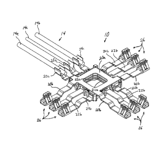
[0019] Referring now to the drawings and the illustrative embodiments depicted
therein, a low
profile electrical terminal assembly 10 is configured for mounting in a
raceway junction 12, such
as shown in FIGS. 1, 2 and 7-8B. Raceway junction 12 receives or conveys
electrical power
from electrical conductors 14 that are routed through a raceway 16, which is
coupled to raceway
junction 12. In the illustrative embodiment of FIGS. 2 and 7, raceway junction
12 includes three
electrical receptacles 18 corresponding to three sets of electrical terminals
of electrical terminal
assembly 10, as will be described below. The configuration of low profile
electrical terminal
assembly 10 permits two or more conductive bodies to be positioned in a thinly
stacked
arrangement, which facilitates a thin or low profile construction for raceway
junction 12, which
may be used to route electrical power in different directions and to different
locations within a
region such as work area.
[0020] In the illustrated embodiment, low profile electrical ten-ninal
assembly 10 includes three
electrically conductive bodies or elements including a "hot" or line body 20,
a ground body 22,
and a neutral body 24, such as shown in FIGS. 3 and 4. Each electrically
conductive body 20,
22, 24 has a respective main or central body portion 20a, 22a, 24a and also
three conductor arms
or branches 20b, 22b, 24b, that radiate or extend outwardly from the
respective central body
portions 20a, 22a, 24a. In addition, each of the conductor bodies includes a
respective crimp
terminal 20c, 22c, 24c for engaging a respective one of the electrical
conductors 14. Each arm or
branch 20b, 22b, 24b has an electrical terminal 26 at its distal end. In the
illustrated
embodiment, electrical terminals 26 are each configured to establish six or
more points of
contact with a male blade terminal, bus bar, or the like, such as described in
commonly-owned
U.S. patent application, Ser. No. 15/054,708, filed Feb. 26, 2016, entitled
ELECTRICAL
CONTACT RECEPTACLE FOR BUS BARS AND BLADE TERMINALS. It will be
appreciated that the precise style or configuration of electrical terminals
may be varied according
to the needs of a particular application, and is not necessarily limited to
the style of electrical
terminals 26 disclosed herein. However, the disclosed electrical terminals 26
are capable of
establishing significant contact surface area with a blade terminal or the
like, and thus are
suitable for low profile applications such as described herein.
-4-
CA 2926102 2017-08-24
CA 02926102 2016-04-05
10021] In the illustrated embodiment, each main or central body portion 20a,
22a, 24a is
generally square in shape when viewed from above, and defines a central
opening 27, such as for
material and weight savings. Line body 20 has its arms or branches 20b
extending off of three
sides of the generally square main body portion 20a, each branch being
generally arranged as an
extension of a respective leg forming the square main body portion 20a.
Similarly, crimp
terminal 20c extends radially outwardly off of a fourth side of main body
portion 20a. The
neutral body's arms or branches 22b extend radially outwardly from respective
sides of the
generally square main body portion 22a, but branches 22b extend outwardly from
a middle or
central region of each leg of the square main body portion 22a. For purposes
of the present
application, it will be appreciated that the term "radially" is used to refer
to any outwardly-
extending direction.
100221 Similarly to branches 22b, crimped terminal 22c extends radially
outwardly from the
central region of the fourth side of the square main body portion 22a. The
neutral body's arms or
branches 24b are arranged similarly to those of line body 20, except that arms
24b are extensions
of opposite legs of each side of the generally square main body portion 24a.
It will be
appreciated that line body 20, ground body 22, and neutral body 24 may each be
unitarily formed
from a single planar sheet of electrically conductive material in a stamping
process such as a
multi-stage stamping process in which the general plan shape is initially cut
out, followed by
bending or stamping operations in which the final shapes of the branches 20b,
22b, 24b are
formed, along with the forming of crimped terminals 20c, 22c, 24c and
electrical terminals 26.
[0023] With this arrangement of branches for each conductive body, when the
bodies are stacked
together such as shown in FIG. 1, the neutral body's branches 24b are spaced
well apart from the
line body's branches 20b, with ground body's branches 22b positioned between
branches 20b and
branches 24b. Similarly, crimped terminal 22c is disposed between the crimped
terminals 20c
and 24c. The resulting electrical terminal assembly 10 permits branching in up
to three different
directions while providing electrical continuity for a line conductor 14a, a
neutral conductor 14b,
and a ground conductor 14c (FIGS. 1 and 7). However, it is envisioned that
more or fewer
directions of branching are possible by using different shapes or arrangements
of branches. For
example, triangular main bodies would readily accommodate branching in two
directions, and
pentagonal main bodies would readily accommodate branching in four directions.
-5-
CA 02926102 2016-04-05
100241 Each main body portion 20a, 22a, 24a lies in a respective plane P1, P2,
P3 so that main
body portions 20a, 22a, 24a are sufficiently spaced apart in the region where
the respective
bodies 20, 22, 24 overlap or overlie one another, such as shown in FIG. 5. It
will further be
appreciated that the plane P3 in which neutral main body portion 24a lies is
the same as a
terminal plane P4 in which lower or base surfaces or portions of each terminal
26 lie. Thus, the
terminal plane P4 is coplanar with the neutral main body portion 24a, which is
spaced below the
plane P2 of the ground main body portion 22a, which is spaced below the plane
P1 of line main
body portion 20a. In the illustrated embodiment, each terminal 26 also
includes an upwardly-
extending portion that extends above the base portion and, therefore, above
terminal plane P4.
100251 Each electrical terminal 26 has its base or bottom portion lying in
terminal plane P4 due
to the shapes of the corresponding amis or branches 20b, 22b, 24b, such as
shown in FIG. 4.
Because the neutral body's main body portion 24a is coplanar with terminal
plane P4, neutral
branches 24b need not change their elevation between neutral main body portion
24a and the
corresponding electrical terminals 26. However, if clearance is needed for
another component,
such as in raceway junction 12, branch 24b may include an optional rise 28a,
followed by an
elevated region 28b (which may lie in the plane P2 of ground main body portion
22a), and a drop
28c back down to an end region 28d at the level of terminal plane P4 and the
plane P3 of neutral
main body portion 24a, such as shown in FIG. 4. Because ground main body
portion 22a lies in
plane P2 spaced above terminal plane P4, ground branches 22b include a drop
30a down to a
lowered portion 30b that lies in terminal plane P4. Line main body portion 20a
lies in the
highest elevation plane P1 and, therefore, line branches 20b drop the furthest
distance down to
terminal plane P4. Line branches 20b include a first drop region 32a, followed
by a first lowered
region 32b, followed by a second drop region 32c, followed by a second lower
region 32d that
lies in terminal plane P4.
[0026] As will be apparent with reference to FIGS. 1 and 5, when electrical
terminal assembly
is assembled, first lowered region 32b of line branch 20b lies in the same
plane as ground
body 22a and a proximal region of ground branch 22b, which also is the same
plane in which
elevated region 28b of neutral branch 24b lies, so that all of these regions
generally lie in the
same plane P2 as ground main body portion 22a. The branches associated with
crimp terminals
20c, 22c, 24c may also be shaped in a similar manner as branches 20b, 22b,
24b, so that the
-6-
CA 02926102 2016-04-05
distal ends (crimp portions) of crimp terminals 20c, 22c, 24c lie in the same
plane as one another,
such as terminal plane P4.
100271 To ensure that line main body portion 20a does not contact or
electrically arc with ground
main body portion 22a, and to ensure that ground main body portion 22a does
not contact or arc
with neutral main body portion 24a, a pair of insulative bodies including a
first insulator 34 and a
second insulator 36 are positioned between the respective main body portions
20a, 22a, 24a. As
best shown in FIG. 3, first insulator 34 is disposed between the line main
body portion 20a and
ground main body portion 22a, and second insulator 36 is disposed between
ground main body
portion 22a and neutral main body portion 24a. Not only do insulators 34, 36
ensure sufficient
separation of the respective main body portions 20a, 22a, 24a during
installation and operation,
but they also limit or substantially prevent electrical shorts due to
compressive loads atop the
main body portions. This is particularly useful for applications in which the
low profile
electrical terminal assembly 10 is mounted along a floor surface, such as in
raceway junction 12,
in which case insulators 34, 36 ensure separation of the main body portions
20a, 22a, 24a even if
significant compressive weight or force is applied above the main body
portions. Such loads
may be imparted, for example, by a person standing on that region, or by a
piece of equipment or
furniture resting along (or rolling over) the junction 12 above main body
portions 20a, 22a, 24a.
Even if the junction 12 were crushed by an overload condition, it is
envisioned that electrical
terminal assembly 10 would be likely to maintain sufficient separation of the
various conductive
surfaces to avoid an electrical short, owing to the presence of insulators 34,
36 and the offset
arrangement of branches 20b, 22b, 24b and crimp terminals 20c, 22c, 24c,
10028] Each of the insulators 34, 36 is generally square in shape when viewed
from above or in
plan view, and includes a generally square opening 38 that substantially
aligns with the
respective openings 27 formed in the main body portions 20a, 22a, 24a. In the
illustrated
embodiment, the insulators 34, 36 are configured to snap together from either
side of ground
main body portion 22a, so that the insulators may be assembled to ground
conductive body 22
prior to final assembly of electrical terminal assembly 10. To facilitate
alignment of first
insulator 34 relative to second insulator 36, first insulator 34 includes a
pair of downwardly-
extending projections 40 at diagonally-opposite corners, and a pair of notches
42 at the other
diagonally-opposite corners, such as shown in FIG. 3. Similarly, second
insulator 36 includes a
pair of upwardly-extending projections 44 at diagonally-opposite corners
corresponding to
-7-
CA 02926102 2016-04-05
notches 42 of first insulator 34, and notches 46 at the other diagonally-
opposite corners
corresponding downwardly projections 40 of first insulator 34. As best shown
in FIG. 1, notches
42 receive upward projections 44, and notches 46 receive downward projections
40. In addition,
both of the insulators 34, 36 include four resilient latch tabs 48 that engage
respective receiving
regions 50 of the other insulator. Thus, latch tabs 48 cooperate with
receiving regions 50 to
allow the insulators 34, 36 to snap together, with ground main body portion
22a sandwiched
between the respective inwardly-directed surfaces of the insulators 34, 36. If
necessary, first
insulator 34 may be separated from second insulator 36 by prying the
insulators apart to release
latch tabs 48 from the respective receiving regions 50. It is envisioned that
insulators 34, 36 may
be made from substantially any electrically insulating and compression-
resistant material, such
as injection molded resinous plastic. In addition, the positioning of latch
tabs 48 and receiving
regions 50 permit the first insulator 34 to be an identical component to
second insulator 36, so
that two identical insulators or insulative bodies are interchangeable and may
be coupled to one
another simply by rotating one insulator by 90-degrees relative to the other
insulator, such as
shown in FIGS. 3 and 6. Optionally, the insulative bodies may be unitarily
founed and joined
together by a flexible living hinge.
100291 Referring to FIGS. 2 and 7-8B, low profile electrical terminal assembly
10 is positioned
between an upper housing surface 54 and a lower housing surface 56 of raceway
junction 12,
with each set of three electrical terminals 26 aligned with a corresponding
electrical receptacle
region 18, in which openings 58 formed in upper housing surface 54 permit
access to the
respective electrical terminals 26 by respective prongs 60 of male plug 52,
such as shown in
FIGS. 2, 8A, and 8B. When the prongs 60 of respective male plugs 52 are
engaged with the
corresponding electrical terminals 26 of electrical terminal assembly 10, the
prongs 60 establish
electrical connections with the respective electrical conductors 14 that are
routed along raceway
16. This allows electrical power to be routed through electrical conductors 62
associated with
each male plug 52 to another location, such as shown in FIG. 7. Power may be
supplied to
electrical conductors 14 via crimped terminals 64 (FIG. 7), or substantially
any other type of
electrical connection or direct-wiring arrangement. It will further be
appreciated that electrical
power could be supplied to low profile electrical terminal assembly 10 via any
one of male plugs
52 and its corresponding electrical conductors 62, although in that case
female receptacles would
typically be substituted for male plugs 52 and male plugs would be substitutes
for receptacles 26.
-8-
CA 02926102 2016-04-05
100301 Accordingly, the assembled low profile electrical terminal assembly 10
has a thin overall
height, such as shown in FIG. 5, while providing positive insulation between
the overlying
conductive components or surfaces. Branch conductors of different polarities
are laterally
separated from one another, and are shaped so that the corresponding
electrical terminals 26 all
lie in substantially the same common terminal plane P4, and providing
significant electrical
contact areas for receiving the respective terminals of another electrical
connector, such as a
three-pronged male plug 52 (FIGS. 2 and 7-8B). Although the illustrated
embodiment has its
telininal plane P4 located coplanar with the plane P3 of neutral main body
portion 24a, it will be
appreciated that the electrical terminals 26 may be positioned substantially
any desired elevation
by changing the degree to which the respective branches change elevation along
their length.
100311 Changes and modifications in the specifically-described embodiments may
be carried out
without departing from the principles of the present invention, which is
intended to be limited
only by the scope of the appended claims as interpreted according to the
principles of patent law
including the doctrine of equivalents.
-9-