Note: Descriptions are shown in the official language in which they were submitted.
CA 02926114 2016-04-01
Method and apparatus for monitoring at least one
electronic switching contact for a vehicle
Description
The present invention relates to a method and to an
apparatus for monitoring at least one electronic
switching contact, for example for a door system for a
vehicle, and to a circuit for a system, comprising a
multiplicity of elements, for example doors, for a
vehicle.
A state monitoring system of an (electric) switch can be
used to monitor at least the "switch closed" and "switch
open" states or positions. In the case of a 4-pole,
mechanically positively driven switch, in each case two
poles can be assigned to one switching contact, and there
is therefore a normally closed contact and a normally
open contact or two normally closed contacts and two
normally open contacts. The two switching contacts can be
electrically isolated from one another but securely
connected to one another by means of a mechanical
connection. In this context, a switching contact can be
integrated into the main circuit, and the second
positively driven switching contact can serve as a
monitoring contact of the main current contact. That is
to say the second contact serves as a means of monitoring
the first contact.
The object of the present invention is to provide an
improved method and an improved apparatus for monitoring
at least one electronic switching contact for a vehicle,
and an improved circuit for a system, comprising a
multiplicity of elements, for a vehicle.
CA 02926114 2016-04-01
- 2 -
This object is achieved by means of a method and an
apparatus for monitoring at least one electronic
switching contact for a vehicle, and by means of a
circuit for a system, comprising a multiplicity of
elements, for a vehicle as claimed in the main claims.
Electronically monitoring the state of switches makes it
possible, for example, to monitor reliably a two-pole
switch with respect to the through-connection or the
interruption of an electrical line. Such a switch can be
employed in an electrical circuit for any desired field
of use, for example for a machine controller or system
controller. For example, such a switch can be used to
monitor a closed state of a door of a door system. Other
fields of application may comprise, for example, a step
or a stair step, a locking system, a brake unit or a
locking unit of a vehicle.
In contrast to a 4-pole, positively driven switch whose
mechanical coupling of its two contacts requires a
minimum activation stroke, in the case of an electronic
switch state monitoring system it is possible to dispense
with such a minimum activation stroke. In addition, there
is no limitation on the maximum activation speed. The
most suitable switch variant can advantageously be
employed using an electronic switch state monitoring
system for any application. In particular, in contrast to
a 4-pole, positively driven switch it is possible to
dispense with a second contact, as a result of which a
second (monitoring) contact is eliminated. By virtue of
the fact that standard switches can be used, costs are
reduced and installation space is optimized. In addition,
smaller switching paths and a free selection of the
CA 02926114 2016-04-01
- 3 -
activation speeds can be implemented. The electronic
switch state monitoring system permits, for example,
detection of cable breaks and switch contact monitoring
as well as detection of wear on the contact.
A method for monitoring at least one electronic switching
contact for a vehicle, wherein the switching contact has
a first connection for a first electrical line and a
second connection for a second electrical line, comprises
the following steps:
reading a first signal from a first monitoring point,
connected to the first connection, in order to obtain a
first monitoring signal;
reading a second signal from a second monitoring point,
connected to the second connection, in order to obtain a
second monitoring signal; and
combining the first monitoring signal and the second
monitoring signal, in order to determine at least one
state of the at least one switching contact.
An electronic switching contact can be understood to be a
switch by means of which two electrical connection of the
switching contact are either connected to one another in
an electrically conductive fashion or electrically
insulated from one another depending on the switched
state of the switching contact. The switching contact can
therefore be employed to interrupt a line in a controlled
fashion. The state of the switching contact can be
monitored by carrying out the steps of the method. The
state can specify, for example, whether the switching
contact is opened or closed, what resistance or impedance
CA 02926114 2016-04-01
- 4 -
the switching contact has or which characteristic or
signal form a signal which passes through the switching
contact has.
Merely by way of example, the switching contact can be
part of a door system of a vehicle. Such a vehicle may
be, for example, a rail vehicle. The switching contact
can be arranged in what is referred to as a dead man's
switch, by means of which a closed state of the doors of
the vehicle can be monitored.
The first and second monitoring points can be arranged on
opposite sides of the switching contact. A monitoring
point can be understood to be an electrical contact or a
coupling apparatus. The monitoring point can be arranged,
for example, directly at a connection of the switching
contact or in the course of a line connected to the
connection. A signal can be understood to be an
electrical current or an electrical voltage. The signal
can be a direct current on which an interference signal
is superimposed. The signal can be tapped by the
monitoring point. A corresponding monitoring signal can
correspond to the read signal or can represent the read
signal. For example, the monitoring signal can comprise a
value sequence which can be determined by sampling the
signal. If the monitoring point is embodied as a coupling
apparatus which permits electrical isolation, the
monitoring signal can be tapped free of potential from
the connections of the switching contact or from lines
connected to the connections of the switching contact.
The combination of the monitoring signals can be carried
out by using a suitable combination rule. For example,
the two monitoring signals can be compared with one
CA 02926114 2016-04-01
- 5 -
another by means of the combination. The state can be
determined by evaluating a result of the combination.
For example, in the combining step, the first monitoring
signal and the second monitoring signal can be examined
for similarity, in order to determine the at least one
state of the at least one switching contact. At least two
degrees of similarity can be defined. Depending on
whether the examination for similarity reveals that the
first or the second degree of similarity is present,
either a first or a second state of the switching contact
can be determined. For example, a closed state of the
switching contact can be determined if a high degree of
similarity is present, and an open state of the switching
contact can be determined if a low degree of similarity
is present. In this way, a relevant state of the
switching contact can be reliably determined.
According to one embodiment, in the combining step the
first monitoring signal and the second monitoring signal
can be correlated with one another, in order to determine
the at least one state of the at least one switching
contact. By means of a correlation, monitoring signals
with a chronologically variable signal form can also be
compared. It is thus possible, for example, to use, for
the determination of the state, high-frequency
interference signals which are represented in the
monitoring signals. Such interference signals are
typically always present owing to electromagnetic fields
in the surroundings of the switching contact.
In the step of reading the first signal, the first signal
can be read by a first contact of the first monitoring
point. In this context, a second contact of the first
CA 02926114 2016-04-01
- 6 -
monitoring point can be connected to the first
connection, and the first and the second contacts of the
first monitoring point can be electrically isolated from
one another. In the step of reading the second signal,
the second signal can be read by a first contact of the
second monitoring point. In this context, a second
contact of the second monitoring point can be connected
to the second connection, and the first and second
contacts of the second monitoring point can be
electrically isolated from one another. Such a monitoring
point may be embodied, for example, as a capacitor. In
this way, it is possible to monitor a switching contact
which is located in a loop which is electrically
disconnected from the surroundings, for example a dead
man's switch.
According to one embodiment, the method can comprise a
step of applying a diagnostic signal to the first
connection and/or the second connection as a function of
the at least one state of the switching contact which is
determined in the combining step. In this context, the
steps of reading and combining can be carried out again
in response to the applying step. For example, an
alternating voltage can be applied to the switching
contact by means of the diagnostic signal. The diagnostic
signal can have a signal form which differs from signal
forms which are typically applied to the switching
contact. The diagnostic signal can be used to determine
the state again or to determine a further state of the
switching contact.
The method as claimed in one of the preceding claims, in
which in the combining step a switched state of the at
least one switching contact is determined as the at least
CA 02926114 2016-04-01
- 7 -
one state. For example, in this way it is possible to
differentiate between an open state and a closed state of
the switching contact.
Correspondingly, in the combining step an electrical
resistance of the switching contact and additionally or
alternatively an impedance of the switching contact can
be determined as the at least one state. As a result, for
example a state of wear of the switching contact can be
determined. Correspondingly, an electrical resistance
between an electrical potential of the switching contact
and a further electrical potential can be determined as
the state. As a result, for example a leakage current can
be detected.
Correspondingly, in the combining step a characteristic
of an interference signal which is applied to the first
connection or the second connection can be determined as
the at least one state. In this way, for example the
presence of an interference field can be detected.
According to one embodiment, the method can comprise a
step of reading a third signal from a third monitoring
point. The third monitoring point can be connected to a
connection for a further switching contact which is
connected in series with the switching contact, in order
to obtain a third monitoring signal. In this context, in
the combining step the third monitoring signal and either
the first monitoring signal or the second monitoring
signal or a further monitoring signal can be combined, in
order to determine at least one state of the further
switching contact. The further monitoring signal can be
used if two monitoring points are arranged in a
connecting line between the two switching contacts.
CA 02926114 2016-001
- 8 -
Correspondingly, further switching contacts can be
monitored by using further monitoring signals.
An apparatus for monitoring at least one electronic
switching contact for a vehicle, wherein the switching
contact has a first connection for a first electrical
line, and a second connection for a second electrical
line, has the following features:
a first reading device for reading a first signal from a
first monitoring point, connected to the first
connection, in order to obtain a first monitoring signal;
a second reading device for reading a second signal from
a second monitoring point, connected to the second
connection, in order to obtain a second monitoring
signal; and
a combining device for combining the first monitoring
signal and the second monitoring signal, in order to
determine at least one state of the switching contact.
An apparatus can be understood to be an electrical
appliance or an electrical circuit, for example an
integrated circuit. The apparatus may be designed to
receive and output signals via suitable interfaces.
A circuit for a system, comprising a multiplicity of
elements, for a vehicle has the following features:
a series circuit composed of a multiplicity of electronic
switching contacts, wherein in each case one switching
contact is assigned to one of the elements, and each of
the switching contacts has a coupling interface to an
CA 02926114 2016-04-01
- 9 -
element assigned to the switching contact, in order to
represent a closed state of the assigned element by means
of a switched state of the switching contact;
a multiplicity of monitoring points which are arranged in
the series circuit, wherein each connection of the
switching contacts is assigned a monitoring point; and
an apparatus for monitoring the multiplicity of switching
contacts, wherein the apparatus has a number of reading
devices which corresponds to the multiplicity of
monitoring points, said reading devices being each
connected to one of the monitoring points and designed to
each read a signal from one of the monitoring points, in
order to obtain one monitoring signal per monitoring
point, and wherein the apparatus has a combining device
which is designed to combine the monitoring signals, in
order to determine at least one state of each one of the
switching contacts.
The switching contacts may be, for example, part of what
is referred to as a dead-man's switch. The switching
contacts can be checked, for example, for faults by means
of the monitoring apparatus. The system can be an entry
system, for example a door system, a step system or a
locking unit, or a drive system, for example a brake
system, of the vehicle. Correspondingly, an element can
be, for example, a door, a step, a locking mechanism or a
brake unit.
According to one embodiment, a first end of the series
circuit can be embodied as an interface to a power
supply. The series circuit can have an electromagnetic
switch at a second end opposite the first end. The
CA 02926114 2016-04-01
- 10 -
circuit can have at least one further monitoring point,
which is assigned to at least one connection of the
electromagnetic switch and can have at least one further
reading device which is connected to the at least one
further monitoring point and which is designed to read a
signal from the at least one further monitoring point, in
order to obtain at least one further monitoring signal.
The combining device can be designed to determine a
capacitive or inductive behavior of the electromagnetic
switch arranged in the series circuit by using the
further monitoring signal as at least one state of the
electromagnetic switch. The electromagnetic switch may
be, for example, a contactor. The state may indicate, for
example, that the electromagnetic switch has a defect.
Alternatively, the state can indicate, for example, that
the electromagnetic switch is ready for use.
Preferred exemplary embodiments of the present invention
are explained in more detail below with reference to the
appended drawings, in which:
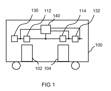
fig. 1 shows a schematic illustration of a vehicle
according to an exemplary embodiment of the
present invention; and
fig. 2 shows a schematic illustration of an apparatus
for monitoring a switching contact according to
an exemplary embodiment of the present invention;
fig. 3 shows a flowchart of a method for monitoring a
switching contact according to an exemplary
embodiment of the present invention;
CA 02926114 2016-04-01
- 11 -
fig. 4 shows a circuit for a door system, comprising a
multiplicity of doors, according to an exemplary
embodiment of the present invention;
fig. 5 shows a block diagram of an electronic switching
contact monitoring system according to an
exemplary embodiment of the present invention;
and
fig. 6 shows an illustration of EMC approval limits
according to an exemplary embodiment of the
present invention.
In the following description of the preferred exemplary
embodiments of the present invention, identical or
similar reference symbols are used for the elements which
are illustrated in the various drawings and which act
similarly, wherein a repeated description of these
elements is omitted.
Fig. 1 shows a schematic illustration of a vehicle 100
according to an exemplary embodiment of the present
invention. The vehicle 100 may be, for example, a rail
vehicle. The vehicle 100 has two doors 102, 104. Each
door 102, 104 is assigned a separate switching contact
112, 114, also referred to as switches. The first
switching contact 112 is assigned to the first door 102,
and the second switching contact 104 to the second door
104. The first switching contact 112 is mechanically
coupled to the first door 102. If the first door 102 is
opened, or not completely closed, the first switching
contact 112 is open. This can also be correspondingly
inverted in the case of the first switching contact 112
and the further switching contacts 114. If the first door
CA 02926114 2016-04-01
- 12 -
102 is closed, the first switching contact 112 is closed.
The second switching contact 114 is mechanically coupled
to the second door 104. If the second door 104 is opened,
or not completely closed, the second switching contact
114 is open. If the second door 104 is closed, the second
switching contact 114 is closed. In a closed state of the
switching contacts 112, 114, a flow of current through
the switching contacts 112, 114 is possible.
The switching contacts 112, 114 are connected in a series
circuit. At one end of the series circuit, a signal is
fed into the series circuit via a power supply 130, for
example in the form of a voltage source. The signal may
be for example, a direct current which flows through the
switching contacts 112, 114 when the switching contacts
112, 114 are all closed. If one of the switching contacts
112, 114 is open, the flow of current through the series
circuit is interrupted. On the basis of the flow of
current it is therefore possible to detect that all the
doors 102, 104 are closed or that at least one of the
doors 102, 104 is opened.
An apparatus 140 for monitoring the switching contacts
112, 114 is connected via switching lines to the
connections of the switching contacts 112, 114, and
according to one exemplary embodiment to the connections
of the contactor 132. The apparatus 140 is designed to
monitor states of the switching contacts 112, 114, and
according to an exemplary embodiment, of the contactor
132.
The exemplary embodiment of a door system is selected by
way of example. Instead of doors 102, 104, other elements
of the vehicle 100 can also be monitored using the
CA 02926114 2016-04-01
- 13 -
switching contacts 112, 114. The switching contacts 112,
114 can be arranged in what is referred to as a dead
man's switch.
Fig. 2 shows a schematic illustration of an apparatus 140
for monitoring a switching contact 112 according to an
exemplary embodiment of the present invention. This may
be the apparatus shown in fig. 1. The switching contact
112 may be one of the switching contacts which are shown
in fig. 1.
The switching contact 112 has a first connection 251
which is connected to a first line 252. In addition, the
switching contact 112 has a second connection 254 which
is connected to a second line 255. On the side of the
first connection 251, for example at the first connection
251 or on the first line 252, a first monitoring point
261 is arranged which is connected to the apparatus 140
via a first monitoring line 262. On the side of the
second connection 254, for example at the second
connection 254 or at the second line 255, a second
monitoring point 264 is arranged which is connected to
the apparatus 140 via a second monitoring line 265.
The apparatus 140 has a first reading device 271, a
second reading device 273 and a combining device 275. The
first reading device 271 is designed to read, via the
first monitoring line 262 and the first monitoring point
261, a signal which is applied to the first connection
251 or the first line 252, and to output the said signal
as a first monitoring signal to the combining device 275.
The second reading device 273 is designed to read, via
the second monitoring line 265 and the second monitoring
point 264, a signal which is applied to the second
CA 02926114 2016-04-01
- 14 -
connection 254 or the second line 255 and to output said
signal as a second monitoring signal to the combining
device 275. The combining device 275 is designed to
combine the first monitoring signal and the second
monitoring signal with one another, for example to
compare or to correlate them with one another in order to
determine at least one state of the switching contact
112. For example, the combining device 275 can be
designed to combine the two monitoring signals, in order
to determine a similarity value which represents a
similarity between the monitoring signals. If a high
degree of similarity is present, the state of the
switching contact 112 may be determined, for example, as
being closed. If a low degree of similarity is present,
the state of the switching contact 112 may be determined,
for example, as being opened. The presence of a high or
low degree of similarity can be determined, for example,
by a comparison of the similarity value with a threshold
value. The combining device 275 can also be designed to
use one or both of the monitoring signals to carry out an
impedance measurement, with the result that an impedance
of the switching contact 112 can be determined, or to
carry out a resistance measurement, with the result that
a resistance of the switching contact 112 can be
determined.
According to one exemplary embodiment, the apparatus 140
is designed to output a state signal which represents the
state which is determined for the switching contact 112.
The state signal can be processed, for example, by a
central control apparatus, for example of a vehicle.
According to one exemplary embodiment, the apparatus 140
is designed to feed a diagnostic signal 279 into one of
CA 02926114 2016-04-01
- 15 -
the connections 251, 254 or into one of the lines 252,
255. For example, the apparatus 140 can be designed to
feed the diagnostic signal 279 into one of the monitoring
points 261, 264. The diagnostic signal 279 can be fed via
one of the monitoring lines 262, 265 or via an additional
diagnostic line. The diagnostic signal 279 can be a
constant signal, for example a direct voltage, or an
alternating signal with a characteristic signal form that
changes over time. After or during the feeding-in of the
diagnostic signal 279, the apparatus 140 can be designed
to read a monitoring signal via at least one of the
reading devices 271, 273 and to compare the two read
monitoring signals with one another or to compare one of
the monitoring signals with the diagnostic signal 279 in
the combining device 275. By using the fed-in diagnostic
signal 279, one of the states of the switching contact
112 which has already been determined can be checked or a
further state can be detected.
In a corresponding form, the apparatus 140 can be used to
monitor a multiplicity of switching contacts, as is
shown, for example, below in fig. 4. In this context,
each switching contact can be arranged between two
monitoring points, or two or more switching contacts can
also be arranged between two adjacent monitoring points.
It is also possible to arrange just one monitoring point
between two adjacent switching contacts, wherein the
signal which is read via this monitoring point can be
used to monitor the two adjoining switching contacts.
The lines 252, 255 and the switching contact 112 can be
electrically decoupled from the monitoring lines 262, 265
and from a line for conducting the diagnostic signal 279.
This can be achieved, for example, by virtue of the fact
CA 02926114 2016-04-01
- 16 -
that the monitoring signals are decoupled from the lines
252, 255 by means of capacitors arranged at the
monitoring points 261, 264. Correspondingly, the
diagnostic signal 279 can be coupled into the line 252
via a further capacitor.
According to one exemplary embodiment, the lines 252, 255
and the switching contact 112 are part of a dead man's
switch. In this context, there is an electric isolation
between the dead man's switch and an evaluation which can
be carried out, for example, in the apparatus 140. As a
result, the potentials of the evaluation and the dead
man's switch are isolated from one another. There is
therefore no ground connection. If the switching contact
112 or all of the other switching contacts 112 of the
dead man's switch are also open, there is no ground
connection. Nevertheless, the monitoring can be carried
out by virtue of the fact that the alternating current
resistance of a structure, here, for example, of the
switching contact 112, is determined.
According to one exemplary embodiment, the dead man's
switch or the signal of the dead man's switch, typically
a direct voltage signal, must not be influenced by "third
parties". For this reason, very low signal powers are
used, which are below the EMC approval, such as is
explained below with reference to fig. 6. The dead man's
switch is kept electrically isolated from all the other
signals. This is achieved, for example, by means of a
capacitor. The alternating voltage signal in the form of
the diagnostic signal 279 is coupled into the dead man's
switch via the capacitor or a further capacitor and is
decoupled free of direct voltage again via a second
capacitor. The problem of groundless detection -
CA 02926114 2016-04-01
- 17 -
theoretically all the switches can be open or some open
and some closed - is that unknown potential influences
are present. On the basis thereof, the diagnostic signal
279 is selected in such a way that the alternating
voltage resistance of the cable, for example between the
one supply point of the diagnostic signal 279 and the
monitoring point 264, is sufficient to generate a
necessary signal amplitude for the evaluation circuit
140. The basic idea of this approach is to measure an
alternating current resistance of an unknown structure
and to derive possible errors therefrom with suitable
methods. The diagnostic signal, in particular a frequency
of the diagnostic signal, can be selected suitably in
accordance with the inductive and capacitive behavior of
the structure. For example, in the case of a very low
inductance or capacitance of the structure, a diagnostic
signal with a high frequency can be selected. In
conventional methods, direct voltage signals are used as
a diagnostic signal or there may be no electric isolation
present. The system is limited here not only to drives
but can very generally also be employed for, for example,
stair steps, brake units or locking units or locking
systems.
Fig. 3 shows a flowchart of a method for monitoring a
switching contact according to an exemplary embodiment of
the present invention. The method can be implemented, for
example, by apparatuses of the apparatus shown in fig. 2.
In a step 381, a first signal is read by a first
monitoring point which is connected to a first connection
of the switching contact. On the basis of the first
signal, a first monitoring signal is generated, for
example by sampling the first signal.
CA 02926114 2016-001
- 18 -
In a step 383, a second signal is read by a second
monitoring point which is connected to a second
connection of the switching contact. On the basis of the
second signal, a second monitoring signal is generated,
for example by sampling the second signal.
In a step 385, the first monitoring signal and the second
monitoring signal are combined. As a result, one or more
states of the at least one switching contact which relate
to different parameters of the switching contact are
determined.
In an optional step 387, a diagnostic signal can be
coupled as an actively generated interference signal into
one of the connections or to a line which is connected to
one of the connections. Subsequently, the steps 381, 383,
385 can be carried out repeatedly.
Fig. 4 shows a circuit for a door system comprising a
multiplicity of doors, according to an exemplary
embodiment of the present invention. By way of example,
three switching contacts 112, 114, 416 and an apparatus
140 for monitoring the switching contacts 112, 114, 416,
as has already been described with reference to the
preceding figures, are shown.
The switching contacts 112, 114, 416 are connected in
series. A first connection of the first switching contact
112 is connected to a power supply 130, for example a
144V direct voltage source. A second connection of the
first switching contact 112 is connected to a first
connection of the first switching contact 114. A second
connection of the second switching contact 114 is
CA 02926114 2016-04-01
- 19 -
connected to a first connection of the third switching
contact 416.
The arrangement composed of switching contacts 112, 114,
416 and power supply 130 can be referred to as what is
referred to as a dead man's switch by means of which the
closed state of vehicle doors can be monitored. A
switching signal for a control apparatus, for example
what is referred to as an MDCU unit, can be generated by
means of the power supply 130 and the switching contacts
112, 114, 416.
The apparatus 140 is connected via a first monitoring
line to the first connection of the first switching
contact 112, via a second monitoring line to the second
connection of the second switching contact 112, via a
third monitoring line to the first connection of the
second switching contact 114, via a fourth monitoring
line to the second connection of the second switching
contact 114, via a fifth monitoring line to the first
connection of the third switching contact 416, and via a
sixth monitoring line to the second connection of the
third switching contact 416. At least one of the
monitoring lines can be designed to feed a diagnostic
signal from the apparatus 140 into one of the connections
of the switching contacts 112, 114, 416. Alternatively,
at least one additional line can be provided for
conducting at least one diagnostic signal.
The second connection of the third switching contact 416
can be connected, for example, to a first connection of a
further switching contact, to a connection of a safe
contactor or to a connection of an evaluation device
which is designed to detect, for example by means of
current measurement or voltage measurement, whether there
CA 02926114 2016-001
- 20 -
is a continuous connection to the power supply 130, on
the basis of .which it can be inferred that all the
switching contacts 112, 114, 416 are closed.
In the electrical lines connected to the connections of
the switching contacts 112, 114, 416, interference
signals can occur, for example, owing to interference
fields. The interference signals can be detected by means
of the monitoring lines and employed to monitor the
switching contacts 112, 114, 416. For this purpose,
interference signals which are detected, for example, by
means of two different monitoring lines, or monitoring
signals derived therefrom, can be evaluated in terms of
their form, their chronological offset or their
chronological offset between the current and the voltage.
As a result, an electronic switch state monitoring system
or an electronic switching contact monitoring system can
be implemented. What is referred to as the super-
heterodyne principle of signal superimposition theory
serves as a basis here. Use is made here of the fact that
there is no interference-free DC signal that is conducted
in this exemplary embodiment from the power supply 130
through the switching contacts 112, 114, 416, and that
each DC signal also has interferences superimposed on it
(AC signal).
Electromagnetic fields, mobile radio beams, for example
of the GSM standard, switching processes or general
noise, as considered, for example, within the scope of
electromagnetic compatibility (EMC), can serve as
interference sources.
CA 02926114 2016-001
- 21 -
It can be assumed that the interference (considered quite
generally) remains constant over the structure to be
considered. This means that on condition that the switch
is closed, the interferences at the input of the switch
are also present at the output of the switch.
In order to increase the detection probability of the
switch position of the switching contacts 112, 114, 416,
a second interference signal, also referred to as a
diagnostic signal, can additionally be introduced
actively into the system, which signal can also be
measured in the case of the closed switch position of the
switching contacts 112, 114, 416 both at the input and at
the output, that is to say the two connections of one of
the switching contacts 112, 114, 416 or a series circuit
composed of a plurality of, or of all of, the switching
contacts 112, 114, 416.
The apparatus can check the switching contacts 112, 114,
416, for example, for impedance and conductivity, or can
determine values relating to the impedance and
conductivity. According to one exemplary embodiment, the
apparatus 140 is embodied as a digital signal controller.
Independent analysis for impedance and conductivity of a
conductor loop is therefore possible by means of a
digital signal controller.
According to one exemplary embodiment, the inputs of the
apparatus 140 are sampled and compared for similarity.
For this purpose, for example a cross-correlation or
Fourier transformation can be carried out. If the
similarity of the sampled signals is very high, from
which it can be inferred that the switching contact 112,
114, 416, also referred to as a switch, being considered
CA 02926114 2016-04-01
- 22 -
is closed, an attempt is made to bring about a difference
by applying a digitally generated interference signal,
also referred to as a diagnostic signal, to one or both
lines which are connected to the connections of the
switching contact 112, 114, 416 being considered. If the
similarity of the sampled values of the sampled signals
remains the same to a certain degree, the switching
contact 112, 114, 416 being considered is unambiguously
closed. In this case, the apparatus 140 can be designed
to output a corresponding state signal which indicates
the state of the switching contact 112, 114, 416 being
considered.
According to one exemplary embodiment, the apparatus 140
can make available the following possible measurement
results. On the one hand, the switched state at the
switch 112, 114, 416 and the state of the lines between
the switches 112, 114, 416 can be determined. In
addition, the resistance of the switch 112, 114, 416 can
be determined, for example, in order to detect the wear,
or in the case of a plug connection, to find contact
faults or cable breaks. In addition, leakage currents or
contact resistances with respect to other electrical
potentials can be determined, for example, by measuring
the electrical isolation with respect, for example, to a
vehicle bodywork. A complex indicator of a resistance can
be determined as a measurement result. The complex
indicator of the resistance can be used to detect whether
the section between two relevant monitoring points of the
signals is capacitive or inductive. This permits
detection of whether a safety contactor at the end of the
line is in order. In addition, an evaluation of the
generally occurring interference fields in the loop which
CA 02926114 2016-04-01
- 23 -
is conducted through the switching contacts 112, 114, 416
is possible.
Fig. 5 shows a block diagram of an apparatus 140 for
monitoring at least one switching contact according to an
exemplary embodiment of the present invention. The
apparatus 140 has on the input side an input filter 581,
for example a bandpass, a microprocessor 583 for
evaluating the signal differences and on the output side
an output filter 585 for an active interference signal.
The input filter 581 is designed to subject signals read,
for example, by suitable monitoring points at at least
one switching contact to input filtering. The
microprocessor 583 is designed to combine or compare the
filtered signals. The output filter 585 is designed to
subject a diagnostic signal, in the form of the active
interference signal, provided for feeding into the at
least one switching contact to output filtering.
Such an apparatus 140 can be implemented as a standalone
variant, that is to say as an independent apparatus, or
as a variant which is indicated completely into a further
control apparatus.
Fig. 6 shows an illustration of EMC approval limits
according to an exemplary embodiment of the present
invention. A diagram in which the frequency in Hertz is
plotted on the abscissa and the field strength in volts
per meter is plotted on the ordinate is shown. A
characteristic curve 691 which represents an EMC limit,
below which the products thereof must be fully
functionally capable, is indicated. In addition, a
characteristic curve 693 is indicated which shows an EMC
CA 02926114 2016-04-01
- 24 -
limit of the electronic switching contact monitoring
system, which can be implemented, for example, by a
described apparatus for monitoring at least one switching
contact.
Full EMC capability as well as the .irradiation and
emission concerned are given by means of the EMC approval
limits shown in fig. 6. In addition, a minimum operating
capacity and therefore a position below the EMC approval
limits is given.
The described approach permits the use of standard
switches in a monitoring loop, for example one referred
to as a dead man's switch.
Such switches permit, when necessary, a small activation
path of, for example, less than 4.9 mm, a high activation
speed of, for example, over 1 m/s, a large activation
force of, for example, over 3N and a restoring force of,
for example, less than 0.2N.
As a result, failures of the switches owing to
excessively high activation speeds can be avoided. Short
activation paths can also be implemented, and a precise
switch setting is not necessary. In addition, the space
required can be kept smaller and the costs can be kept
low. In addition, the specification of such a circuit can
be kept simple, as a result of which new developments,
for example the use of a magnetic brake, can be made
inexpensive.
The described exemplary embodiments are selected only by
way of example and can be combined with one another.
CA 02926114 2016-04-01
- 25 -
List of reference numbers
100 Vehicle
102 Door
104 Door
112 Switching contact
114 Switching contact
130 Power supply
132 Contactor
140 Monitoring device
251 First connection
252 First line
254 Second connection
256 Second line
261 First monitoring point
262 First monitoring line
264 Second monitoring point
265 Second monitoring line
271 Reading device
273 Reading device
275 Combining device
278 State signal
279 Diagnostic signal
416 Switching contact
581 Input filter
583 Microprocessor
585 Output filter
691 Characteristic curve
693 Characteristic curve