Note: Descriptions are shown in the official language in which they were submitted.
CA 02926403 2016-04-05
WO 2015/065835 PCT/US2014/062142
1
LATE STAGE ADDITION OF RHEOLOGY MODIFIER
FIELD OF THE INVENTION
The present invention relates to methods of making personal care compositions,
such as
dentifrices, specifically methods involving the addition of theology modifiers
at a later stage in
the personal care composition formation process.
BACKGROUND OF THE INVENTION
Dentifrice is typically made in vacuum vessels using some type of high energy
mixing device, to
combine the various components. The liquids are usually added to the vacuum
vessel as a first
step. Flavor or other oils can be added at various points within the batch
during the mixing
process to minimize loss and maximize within batch antifoaming benefits. The
salts are added
either directly to the mix tank or added to a slurry tank first then added to
the mix tank. The
abrasive is typically added directly to the mix tank, however it is possible
the abrasive could be
pre slurried and delivered to the mix tank as a premix.
Rheology modifiers are either added directly to the mix tank or added via
offline pre slurry (tank
or inline). The direct to the tank option requires significant within batch
mixing (typically high
energy) which can take significant processing time to complete. The offline
option requires more
capital assets to support the different formulations. Typically the final step
of currently used
processes is the addition of the surfactant. Keeping the surfactant to the end
of the batch makes
tank deaeration easier to complete. Even with holding the surfactant to the
end of the process,
when making the dentifrice batch on the residual of the previous batch, the
residual surfactant
from the first batch can cause significant challenges on deaeration. These
challenges can account
for up to 30% of the total process time in making toothpaste.
The ingredients are typically combined together in the mix tank by
recirculating the ingredients
through a high shear mixing device to create a final homogenous product
composition. Vacuum
is then applied to the mix tank to deaerate the dentifrice to the desired
finished density. The
addition of rheology modifiers thickens the premix making dearation more
difficult, as it is
harder to pull air out of a thick premix. Due to the addition of the rheology
modifiers during the
CA 02926403 2016-04-05
WO 2015/065835 PCT/US2014/062142
2
mixing process the premix has a paste like viscosity that clings to the
internal mix tank surfaces,
preventing the complete removal of the premix when it is pumped out of the mix
tank. This
requires the mix tank to be cleaned prior to making another product formula.
It currently takes
substantial length of time ( > 1 hr) and large amounts of water to clean a mix
tank. This results in
a greatly reduced making capacity due to lost time, as new formulas cannot be
made while the
system is being cleaned. Therefore due to the high viscosity of the finished
product, processing
time is slow and losses are high.
What is needed is a personal care composition making methodology that has
reduced down-time
due to inter batch cleaning times.
SUMMARY OF THE INVENTION
A method of producing a personal care composition is provided that comprises
forming in a mix
tank premix having a lower viscosity than a packaged personal care
composition; transferring the
premix from the mix tank; adding rheology modifier to the premix; deaerating
the premix; and
packaging the premix to produce a personal care composition.
A method of producing a personal care composition is provided that comprises
forming in a mix
tank premix having a lower viscosity than a packaged personal care
composition; transferring the
premix from the mix tank to a high energy dispersion device; adding rheology
modifier to the
premix; deaerating the premix using an inline deaeration device; and packaging
the premix to
produce a personal care composition; wherein the inline deaeration device is
positioned such that
the pressure drop between the high energy dispersion device and inline
deaeration device is less
than the pumping pressure head of the high energy dispersion device.
BRIEF DESCRIPTION OF THE DRAWINGS
FIG. 1 is a process flow chart showing an embodiment of the present invention.
FIG. 2 is a process flow chart showing an embodiment of the present invention.
FIG. 3 is a perspective view of a test mixing vessel.
CA 02926403 2016-04-05
WO 2015/065835 PCT/US2014/062142
3
FIG. 4 is a side view of a mix impeller.
DETAILED DESCRIPTION OF THE INVENTION
The present invention involves the late addition of rheology modifiers to a
dentifrice premix.
Losses from washout of the mix tank, due to a thickened premix, are minimized
and throughput
of the process in the mix tank is faster because of lower rheology. The low
rheology of the
premix also increases the efficiency and speed of deaeration, which may be
conducted prior to an
increase in viscosity, such as in line, prior to pumping through a high shear
mill or in the mix
tank. In certain embodiments the deaeration of the premix is done prior to the
addition of
surfactant to reduce the generation of micelles.
All parts, percentages and proportions referred to herein and in the claims
are by weight of the
total oral composition unless otherwise indicated. All measurements are made
at 25 deg. C. on
the total oral composition unless otherwise indicated.
As used herein, the word "or" when used as a connector of two or more elements
is meant to
include the elements individually and in combination; for example X or Y,
means X or Y or both.
By "personal care composition" is meant a product which in the ordinary course
of usage is
applied to or contacted with a body surface to provide a beneficial effect.
Body surface includes
skin, for example dermal or mucosal; body surface also includes structures
associated with the
body surface for example hair, teeth, or nails. Examples of personal care
compositions include a
product applied to a human body for improving appearance, cleansing, odor
control or general
aesthetics. Non-limiting examples of personal care compositions include hair
coloring
compositions, oral care compositions, after shave gels and creams, pre-shave
preparations,
shaving gels, creams, or foams, moisturizers and lotions, cough and cold
compositions, leave-on
skin lotions and creams, shampoos, conditioners, shower gels, bar soaps,
toilet bars,
antiperspirants, deodorants, depilatories, lipsticks, foundations, mascara,
sunless tanners and
sunscreen lotions.
By "oral care composition", as used herein, is meant a product, which in the
ordinary course of
usage, is not intentionally swallowed for purposes of systemic administration
of particular
CA 02926403 2016-04-05
WO 2015/065835 PCT/US2014/062142
4
therapeutic agents, but is rather retained in the oral cavity for a time
sufficient to contact dental
surfaces or oral tissues. Examples of oral care compositions include
dentifrice, tooth gel,
subgingival gel, mouth rinse, mousse, foam, mouth spray, lozenge, chewable
tablet, chewing
gum, tooth whitening strips, floss and floss coatings, breath freshening
dissolvable strips, or
denture care or adhesive product. The oral care composition may also be
incorporated onto strips
or films for direct application or attachment to oral surfaces.
The term "dentifrice", as used herein, includes tooth or subgingival -paste,
gel, or liquid
formulations unless otherwise specified. The dentifrice composition may be a
single phase
composition or may be a combination of two or more separate dentifrice
compositions. The
dentifrice composition may be in any desired form, such as deep striped,
surface striped,
multilayered, having a gel surrounding a paste, or any combination thereof.
Each dentifrice
composition in a dentifrice comprising two or more separate dentifrice
compositions may be
contained in a physically separated compartment of a dispenser and dispensed
side-by-side.
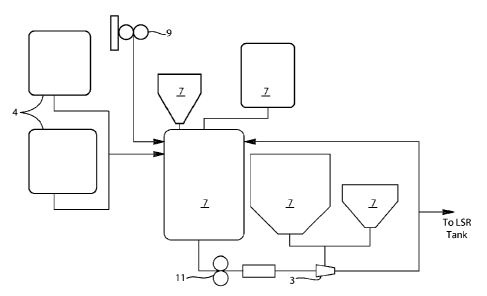
An illustrative processing diagram of the instant invention is depicted in
FIG. 1. The mixing
process begins with the addition of liquids 4 to the mix tank 1. The mix tank
1 provides the
means for preparing a low viscosity slurry of the liquid and solid components
of the mix. The
liquids 4 can be added directly to the mix tank 1, or could be added through
an high energy
dispersion device, such as an eductor, examples of which include a Lobestar
eductor sold by
Vortex Ventures, Houston, TX, allowing powders to be added concurrently with
the liquids.
After the main liquids (typically humectants, water, pH adjuster, and
potentially flavor and
emulsifier/surfactant) are added to the tank the powder (or remaining powder)
7 can be added to
the mix tank 1. In certain embodiments the powder 7 can be added using an
eductor 3, so as to
maximize the dispersion during the addition, which minimizes the total
processing time. The
powders typically start with the salts for the system, then the addition of
the abrasive(s). Visual
ingredients, such as mica, prills, and aesthetic agents, can also be added at
this point. After all
the materials are combined, the batch is mixed for a time to deliver
homogeneity (this time is a
function of the type of dentifrice being made). Mixing can occur under vacuum,
for example by
using a vacuum pump 9, or under atmospheric conditions. In certain embodiments
mixing under
non-vacuum conditions can be done as the low viscosity of the fluid allows for
self deaeration of
the system. Being able to produce under non-vacuum conditions reduces the
energy
consumption of the system improving efficiency of the overall process. So when
possible the
CA 02926403 2016-04-05
WO 2015/065835 PCT/US2014/062142
batch is under atmospheric conditions in the mix tank at a temperature of
about 15 C to about
55 C. The lower viscosity enables shorter mix time to boost process
efficiency.
For example, with reference to FIG. 1, in certain embodiments the mix tank 1
can be charged
5 with Sorbitol, Water, Pigment, Dye and Polysorbate 80 through the main
port and the agitator
controller set to provide sufficient tank turnovers to maintain homogeneity.
To determine
sufficient mixing, a relationship between the system pumping rate and the
settling rate of the
suspension can be used to calculate the system suspension ratio. A system
suspension ratio of
about one or greater insures a system will not settle and maintain
homogeneity. The system
suspension ratio can be determined by first measuring the settling rate of the
suspension. Once
the settling rate of the suspension is determined, the pumping rate of the
system can be
calculated. The system suspension ratio is calculated as follows:
QP
= SSR
SR f x Vb
where: Qp ¨ system pumping rate (see following discussion) (m3/s)
Vb ¨ Equivalent batch volume (m3)
SRf ¨ settling rate of the fluid measured by attached method (1/s)
SSR ¨ System Suspension Ratio
Qp can be measured using a flow meter on an external recirculation loop or by
the following
calculation approach for calculating the pumping rate of the agitator in a
stirred tank; as shown
in: Paul, Edward L. Atiemo-Obeng, Victor A. Kresta, Suzanne M. (2004).
Handbook of
Industrial Mixing - Science and Practice. John Wiley & Sons.
p. 358-360.
Q = NQ x N x D3
Where
NQ = Pumping number which depends on the impeller type, Dir ratio and impeller
Reynolds
number
and the impeller Reynold's number is:
CA 02926403 2016-04-05
WO 2015/065835 PCT/US2014/062142
6
Re=pxNx D2
1-1
N = impeller speed
D = Diameter of the impeller
The Table below gives values for the pumping number for various impellers
under turbulent
conditions. In certain embodiments the pumping number is between about 0.4 NQ
to 0.8 NQ.
TABLE 1
Impeller Type NQ
Propeller 0.4-0.6
Pitched blade turbine 0.79
Hydrofoil impellers 0.55-0.73
Retreat curve blade 0.3
Flat-blade turbine 0.7
Disk flat-blade turbine (Rushton) 0.72
Hollow-blade turbine (Smith) 0.76
The calculated system suspension ratio is a ratio of pumping rate/ settling
rate and in certain
embodiments can be greater than 0.75 or greater than 1. In certain embodiments
as shown in
FIG. 1, for producing premix a recirculation pump 11 controller can be set to
provide a system
suspension ratio of about two or greater and is typically between about 30- Hz
to about 60 Hz
and the mixture can be recirculated through the eductor 3 for about 5 minutes
or less. A flavor
component can then be added to the mix tank 1 through a main port while mixing
and
recirculating through the eductor 3. A powder delivery hose can be connected
to the eductor 3
via a powder delivery port and the Minor powders (sweetener, fluoride source,
phosphates, etc.)
can then be added to the mix tank 1 through the eductor 3 via the powder
delivery hose
connected to the powder delivery port. The batch is recirculated through the
eductor 3 for about
5 minutes or less, or until pass volume of 100% of batch volume has been
achieved. Sodium
hydroxide can then be added to the mix tank 1 via the main port and the batch
recirculated
through eductor 3 for about 5 minutes or less. Silica can then be added to the
mix tank 1 through
the eductor 3 via the powder delivery hose connected to powder delivery port
and the batch again
CA 02926403 2016-04-05
WO 2015/065835 PCT/US2014/062142
7
recirculated through the eductor 3 for about 5 minutes or less, or until pass
volume of 100% of
batch volume has been achieved. The recirculation through the eductor 3 can
then be turned off
while continuing to mix via agitation at a system suspension rate of about 1.5
or greater, until the
batch is transferred into a Late Stage Rheology (LSR) feed tank 20 or fed
directly into the LSR
system, as shown in FIG. 2. Vacuum can then be applied on the mix tank 1 to
remove residual
batch material from lines and transfer to LSR tank 20. It is possible to coat
the mix chamber of
the premix tank to reduce premix adhesion to the surface of the mix chamber,
for example with a
substance like poly(tetrafluoroethene), which could further reduce the losses
within the tank.
In certain embodiments, it is possible to add a small amount of rheology
modifier to the premix
while it is in the mix tank, as an aspect of the present invention involves
low viscosity, such that
when the premix viscosity is measured at 0.1/s after letting the sample rest
for 30-60 minutes, the
viscosity should be below 150 Pa.s to minimize the residual in the system and
maintain the
improved system efficiency.
The agitator controller on the LSR tank 20 can be set to maintain the system
suspension ratio of
about one or greater. In certain embodiments a dust collection system can be
turned on to
minimize dust in the production area. Sufficient quantities (by weight) of
rheology modifiers and
additives are confirmed and available for use in the feeder hoppers 23 and the
feeder hoppers are
placed within an high energy dispersion device 24, such as a Quadro ZC1 24
(Quadro
Engineering, Ontario, Canada). After confirming that a Surfactant tank 26
contains a sufficient
quantity of material, the desired personal care composition recipe, such as a
dentifrice recipe is
selected, for example from a LSR Human Machine Interface (HMI), and setpoints
are matched
with the Formula Card and batch production record (BPR). The high energy
dispersion device
24 speed can be set between about 40Hz and about 60Hz, with the Process
Control valve (PCV)
25 setpoint between about 10% and about 90% open and inline deaeration device
27, such as a
Yokota pump ASP-515 or ASP-610 (Yokota Manufacturing Co. Ltd., Hiroshima,
Japan), which
may have a speed setpoint between about 45 Hz and about 60 Hz. The relatively
small internal
volume, and pumping efficiency of the Yokota ASP-515 or ASP-610 pump, provides
an
advantage versus traditional inline deaeration devices.
The above LSR system can be started in recirculation mode. The typical
temperature of the
premix within the process can be betvveen about 10 C and 60 C, as in certain
embodiments a
CA 02926403 2016-04-05
WO 2015/065835 PCT/US2014/062142
8
higher temperature than about 60 C runs the risk of negatively impacting the
flavor display of the
system. Further, in certain embodiments a temperature lower than about 10 C
becomes energy
prohibitive for keeping/ getting the fluid to that low temperature. The feed
flow rate of the LSR
Feed Pump 28 can be confirmed at setpoints between about 40 L/min and about
250 L/min). The
theology modifier feeder hoppers 23 are monitored while dispensing at the
target rates as defined
by the formula card to produce a desired personal care composition.
Viscosities of the premix may range from about 0.01 Pa.s to about 10 Pa.s when
sampled at 10
sec-1. In certain embodiments the viscosity may be measured with an AR2000
rheometer (TA
Instruments, New Castle, DE). The AR2000 rheometer uses the following
methodology when
measuring rheology: For the conditioning step, the temperature is set to 25 C
and equilibration is
performed for 2 minutes. Steady state flow with increasing shear rate is
measured by ramping
the shear rate (1/s) from 0.001 to 120.0 and setting to Log mode. Three (3)
points per decade are
acquired at 25 C over a sampling period of 3.0 seconds within a tolerance of
5% until two (2)
consecutive points within the tolerance are achieved. The maximum point is
measured over a
time of 1.0 minute. Steady state flow with decreasing shear rate is measured
by ramping the
shear rate (1/s) from 120.0 to 0.01 and setting to Log mode. Three points per
decade are acquired
at 25 C over a sampling period of 10.0 seconds within a tolerance of 5% until
two consecutive
points within the tolerance are achieved. The maximum point is measured over a
time of 1.0
minute.
Once the premix is sufficiently mixed as defined by the system suspension
ratio, as stated
previously, it is then transferred out of the LSR tank 20 through a pump and
flow meter into a
high energy dispersion device 24 (i.e. rotor stator mill), such as a Quadro
ZC1 õ in certain
embodiments at a flow rate from about 10Kg/min to about 1000Kg/ min or from
about 40Kg/min
to about 400Kg/min. "'be high energy dispersion device ensures an even
dispersion of the
rheology modifiers within the main mix stream. In certain embodiments the
rheology modifiers
are added to the high energy dispersion device at a controlled rate so that
they comprise between
about 0.01% to about 4% individually or between about 0.1% to about 10%
collectively, by
weight of the personal care composition, to ensure the right formula ratios
are delivered. The
rheology modifiers can be added in the form of dry powder, agglomerated
powder, agglomerated
powder with other ingredients, premixed powder with other dry ingredients, or
premixed powder
with liquid ingredients. A coating, for example mineral oil, can be added to a
rheology modifier
further impacting how the rheology modifier disperses or hydrates in the
system.
CA 02926403 2016-04-05
WO 2015/065835 PCT/US2014/062142
9
One embodiment of this system would be loss in weight feeders feeding
individual rheology
modifiers into the high energy dispersion device. Typically, soon after adding
the rheology
modifiers, the premix rheology begins to increase. The rate of viscosity
increase is a function of
the type of rheology modifier used, the formulation, and process conditions.
It is also possible to
add visual solid ingredients via the high energy dispersion device as well.
This approach can
provide further process efficiency benefits by reducing the number of times
the premix needs to
be changed over, and allowing efficient splitting of premixes into different
finished product lots.
Examples of rheology modifiers that can be added via this approach are:
xanthan gum,
carboxymethyl cellulose, can-ageenan, carbomer, hydroxyethyl cellulose, guar
gum, or
thickening silica. Examples of visual solid ingredients are titanium dioxide,
polyethyelene specs,
prills, pigmented silicas, or mica.
After leaving the high energy dispersion device the premix then may flow
through an inline
deaeration device 27, such as a Yokota pump ASP-515 or ASP-610. The inline
deaeration
device can remove down to about 0.001% by volume of the premix or less air, as
measured by
sonar detection method, which is below the consumer noticeable air level of
about 0.5% by
volume or greater air, enabling a robust process window. In certain
embodiments the inline
deaeration device can reduce the air level of the premix to about 0.01% or
less, by volume of the
premix. In still further embodiments the inline deaeration device may deliver
the ratio of air
removal to liquid throughput of about 0.15 L/Kg to about 0.6 L/Kg or from
about 0.2 L/Kg to
about 0.5 L/Kg. In addition the size of the inline deaeration device may
deliver a loss (waste in
deaerater)/ throughput ratio of about 1 1/s to about 8 1/s or from about 2 1/s
to about 4 1/s. The
inline deaeration may occur after all dry ingredients have been added to the
stream, so that the air
removal can be maximized. Given that the rheology modifiers begin increasing
rheology as soon
as they are added to the premix (as defined by the rate of hydration of the
system). The rate of
hydration of the formulations is a function of numerous formula components
such as rheology
modifier type, water level, ionic strength, solids loading and other
attributes. In addition, the rate
of hydration is driven by process conditions such as temperature and energy
density of the high
energy dispersion device.
It is also important that the deaeration occur at a rheology lower than
finished product, such as
toothpaste to maximize efficiency (rate), as less energy is required to remove
air from a material
CA 02926403 2016-04-05
WO 2015/065835 PCT/US2014/062142
having a lower theology as compared to a material having a higher theology.
Consequently the
inline deaeration device may be located as close to the high energy dispersion
device as possible.
The inline deaeration device can be positioned such that the pressure drop
between the high
energy dispersion device and inline deaeration device is less than the pumping
pressure head of
5 the high energy dispersion device. In certain embodiments if that is not
possible then the
pressure control valve can be replaced with a positive displacement pump to
control back
pressure on the high energy dispersion device and ensure the premix can be fed
to the inline
deaeration device. This relationship may be defined by the residence time of
the rheology
modifiers from the point of premix contact through the inline deaeration
device and the rate of
10 hydration of the system.
Deaeration efficiency can be improved by reducing or removing foaming
surfactants, such as
sodium lauryl sulfate. Therefore, in certain embodiments the dentifrice
foaming surfactants are
added after the deaeration steps. Emulsifying surfactants such as polysorbate
80 can be used
prior to the deaeration step without appreciable impact to the deaeration
efficiency.
The viscosity of the stream between the high energy dispersion device, and
inline deaeration
device in certain embodiments is between about 0.01 Pa.s and about 1,000 Pa.s
measured at 10
sec-1 and in certain other embodiments between about 0.01 Pa.s and about 100
Pa.s measured at
10 sec-1 using the measurement protocol described above.
The energy density, or the amount of energy transferred to the premix by a
piece of equipment,
of the high energy dispersion device is best defined by the observed
mechanical energy of the
device (typically measured off the VFD or servo motor) and the premix flow
rate through the
system. This energy density has been shown to impact the personal care
composition texture and
the overall rate of hydration of the system. Acceptable energy density as
described above would
be between about 0.5 KW/Kg/s to about 11 KW/Kg/s or from about 3 KW/Kg/s to
about 9
KW/Kg/s. It has also been observed that the energy to achieve acceptable
texture is inversely
related to the rate of hydration when other process conditions are held
constant, such as
temperature. The relationship of rate of hydration to minimal energy density
is typically in the
range of about 0.001 Kg/KWs2 to about 0.10 Kg/KWs2. The values are calculated
by the
following equation:
CA 02926403 2016-04-05
WO 2015/065835 PCT/US2014/062142
11
(1-t10 s ¨ pt0) /PD
( 0)(10s) = RH pmEDQ
where: tLlOs ¨ viscosity measured 10 seconds after dispersed thickener added
(Pa.$)
[tO ¨ viscosity measured of system prior to addition of water soluble polymer
(Pa.$)
PD ¨ Power Draw (KW)
Q ¨ system flow rate (Kg/s)
RHpmED ¨ Rate of Hydration per minimal Energy Density [rate of hydration in
relation
to the energy density of the system versus the rate of hydration by itself];
(Kg/ KWs2)
The following is a description of the method for determining the rate of
hydration. With the
development of a test mixing vessel and mix impeller, it is possible to
understand the evolving
rheology while combining multiple fluid streams, liquids and powders, or
combinations of
materials utilizing a conventional rotational rheometer that correlates to
larger scale
manufacturing processes. The conventional rotational rheometer offers the
benefits of a
precisely controlled motor and a highly sensitive torque sensor. Liquid/liquid
and liquid/powder
combinations can be created utilizing a test mixing vessel and impeller
system. The test mixing
vessel and impeller are designed to aid in dispersion of powders and/or
liquids into other fluids.
Equipment
Test mixing vessel dimensions are optimized to impeller design to provide
adequate liquid/liquid
or liquid/solid mixing. For the rate of hydration experiments, a typical
experimental design is
detailed below for one impeller type and was the design used to support the
rate of hydration data
included in this application. For other impellers, test mixing vessel internal
diameter and height,
as well as impeller diameter, gaps, etc., will be optimized for that impeller.
1. Test mixing vessel:
a. The test mixing vessel is designed to be a miniature version of a
traditional mix tank
Test mixing vessel is constructed of plastic material, typically optically
clear acrylic
or polyvinyl chloride (PVC). As shown in FIG. 3 the test mixing vessel 30 is
cylindrical in shape with a flat bottom and two separate injection ports 32
for material
addition.
b. Test mixing vessel dimensions:
i. Internal diameter: 38.3 mm
CA 02926403 2016-04-05
WO 2015/065835 PCT/US2014/062142
12
ii. Outside diameter: 42 mm
iii. Vessel height: 65mm
iv. Injection port diameter: 5mm, round, spaced 30mm apart approximately
35mm from vessel bottom
2. Mix impeller:
a. As shown in FIG. 4, mix impeller 40 is an impeller design that combines a
traditional
pitch blade turbine with a hydrofoil impeller design. Dimensions for the mix
impeller
corresponding to above test mixing vessel are as follows:
i. Mix impeller blade diameter (BD): 32.5mm
ii. Mix impeller blade width (BW): 13mm
iii. Length of mix impeller shaft (L): 55mm
3. Rheometer:
a. TA Instruments ARG2 or DHR3 controlled stress rheometer (TA Instruments,
New
Castle, DE) equipped with custom peltier base container holder.
4. Methodology:
a. Determine density of dentifrice base fluid via density meter, pygnometer,
etc.
b. Based on fluid density, weigh appropriate amount of dentifrice base
material to
provide 28-30 mI, of fluid into test mixing vessel.
c. Prepare polymer/binder slurries and pre-weigh appropriate combinations to
meet the
product formula card for dosing
i. The binder slurries can be prepared in a system that allows the polymer to
be dispersed without significant swelling. For example, 40% xanthan gum
dispersed in PEG 300, 5% carbopol dispersed in acidified water, etc.
d. Mount test mixing vessel onto base holder and align/center mix impeller
with test
mixing vessel
e. Lower mix impeller into mix chamber of test mixing vessel. Typical side
wall gap
between mix impeller and test mixing vessel is around 5.5mm. Gap will vary for
alternative impeller types and test mixing vessel dimensions.
f. Rheometer methodology
i. A traditional flow - peak hold experiment design is utilized where
viscosity and torque are monitored as a function of shear rate over time.
Rheometer is set to desired temperature
CA 02926403 2016-04-05
WO 2015/065835 PCT/US2014/062142
13
iii. Mix impeller speed is set at desired rpm to generate desired shear rate
of
the impellers. Desired shear rate typically ranges from 1 to several
hundred s-1.
iv. Length of experiment may vary from 1 minute to 10 minutes depending on
the formulation being created. Some formulations with lower water need
to be analyzed over longer time periods up to 1 hour.
v. Time, torque, and viscosity data is collected over the course of the
experiment at the rate of 0.5 to 1 seconds per data point.
g. With impeller in place, start analysis program as powder and/or binder
slurry is
injected into test mixing vessel through the side ports in less than two
seconds.
h. Monitor viscosity and torque over the measurement time with a sampling rate
of less
than once per second.
i. After the defined test run is complete (typically a 10 minute run),
perform Metzner-
Otto corrections to raw data (Ait-kadi A., Marchal P., Choplin L.,
Chrissement, A.,
Bousmina M., "Quantitative Analysis of Mixer-Type Rheometers using the Couette
Analogy", Canadian J. Chem Eng., 80 (6),1166-1174, 2002.).
After leaving the inline deaeration device the premix can then flow to a
liquid injection system
where the remaining premix surfactants can be added to complete the formula.
It can be
desirable to minimize the residence time between the high energy dispersion
device and the
liquid injection system so as to minimize the pressure drop across the system.
Minimizing the
pressure drop across the system allows for smaller more efficient equipment
and smaller line
diameters. The smaller equipment is typically lower cost to purchase and
operate; and the
smaller lines typically have less loss. In certain embodiments the average
residence time
between the high energy dispersion device and the liquid injection system is
from about 5s to
about 30s. The rate of hydration and throughput are related via the following
equation:
( 30s ¨ 0)
_____________________________________ /
( 0)(30s)Q = RHpT
where: 30s ¨ viscosity measured 30 seconds after rheology modifier added
(Pa.$)
¨ viscosity measured of system prior to addition of rheology modifier (Pa.$)
Q ¨ system flow rate (Kg/s)
CA 02926403 2016-04-05
WO 2015/065835 PCT/US2014/062142
14
RHpT ¨ Rate of Hydration per Throughput [relationship of rate of hydration
over system
throughput]; (Kg/s3)
It has been observed that values of RHpT below 0.001 Kg/s3 and up to 1 Kg/s3
provide
acceptable pressure drop through a static mixing system. It is possible that
values above 1 Kg/s3
could be supported with dynamic mixing options as discussed below.
In certain embodiments the surfactants are incorporated within the stream by
in line mixing
technology, such as through using static mixers. In certain embodiments most
of the surfactant is
added after the inline deaeration device so as to maximize efficiencies of the
inline deaeration
process. Static mixers are well known in the art and are generally in the form
of a series of
repeating or random, interlocking plates and, or fins. Static mixers that can
be used in the present
invention include the Chemineer SSC.75-4R-S (KMA 4 element 3/4") available
from Chemineer
Inc., Dayton, OH 45401 and the Koch SMX 4 element mixer (3/4" nominal)
available from
Koch-Glitsch LP Mass Transfer Sales and Engineering. Cincinnati, OH. Another
type of mixer is
that may be used is a dynamic mixer. One type of dynamic mixer is a high shear
mill, such as
those available from IKA Works, Wilmington, NC. Further, if desired, static
mixers or other
inline mixers may be disposed in or with one or more of the inlet tubes or
upstream of the
confluence region. Additionally, surge tanks may be used to provide more
constant flow for
materials combined by the process described and claimed herein. Additionally
or alternatively a
Zanker plate may be utilized.
The choice of mixer can be influenced by the phase structure of the resultant
composition and
optimizing the pressure drop across the system, which is influenced by the
rate of hydration. For
example, for mixing some materials which are used to produce an isotropic
composition, a static
mixer is sufficient. For mixing other materials to produce a lamellar
composition, greater
agitation can be used to build the viscosity of the resultant composition.
Therefore, a dynamic
mixing system may be appropriate, such as a high shear mill. A dynamic mixing
system as used
herein is inclusive of the batch and continuous stir systems which use an
impeller, jet mixing
nozzle, a recirculating loop, gas percolation, rotating or fixed screen or
similar means of agitation
to combine materials therein.
CA 02926403 2016-04-05
WO 2015/065835 PCT/US2014/062142
A finished personal care composition, such as toothpaste, in certain
embodiments, may have a
viscosity ranging from about 1 Pa.s to about 200 Pa.s or from about 1 Pa.s to
about 150 Pa.s
measured at 1 sec-1. In certain embodiments the viscosity can be measured on
an AR2000
rheometer (TA Instruments, New Castle, DE). The AR2000 rheometer uses the
following
5 methodology when measuring rheology: For the conditioning step, the
temperature is set to 25 C
and equilibration is performed for 10 minutes. Steady state flow with
increasing shear rate is
measured by ramping the shear rate (1/s) from 0.001 to 120.0 and setting to
Log mode. Three (3)
points per decade are acquired at 25 C over a sampling period of 3.0 seconds
within a tolerance
of 5% until two (2) consecutive points within the tolerance are achieved. The
maximum point is
10 measured over a time of 1.0 minute. Steady state flow with decreasing
shear rate is measured by
ramping the shear rate (1/s) from 120.0 to 0.01 and setting to Log mode. Three
points per decade
are acquired at 25 C over a sampling period of 10.0 seconds within a tolerance
of 5% until two
consecutive points within the tolerance are achieved. The maximum point is
measured over a
time of 1.0 minute. After leaving this step the premix can be packaged, for
example, into one or
15 more containers having equal or unequal volumes. The container(s)
containing the product may
be ultimately shipped and sold to the consumer, or may be used for transport
and storage of the
mixture as an intermediate. Thus, the container(s) may be selected from a bulk
storage device,
for example, a tank, a tank car, or rail car, or a final package, for example,
a tube, bottle and/or a
tottle. Storing in the interim containers for a given amount of time could
improve filling
performance for striping. The container(s) may be provided with a frangible or
resealable
closure as are well known in the art, and be made of any material suitable for
containing the
materials combined according to the present invention.
In certain embodiments, one or more of the processing methods described herein
may be
employed or in conjunction with one or more additional processing methods and
the products
produced by employing multiple processing methods may be discharged into a
common
container, thereby forming for example, a product having multiple layers,
phases, patterns etc.
Such layers, phases and/or patterns may or may not mix in the container to
form a homogeneous
product. In certain embodiments, the processing method to manufacture a first
phase of a
product may be in a separate location from the processing method to produce a
second or
multiple phases for filling the container with the final multi-phase
composition, such as a
dentifrice with a paste phase and a gel phase.
CA 02926403 2016-04-05
WO 2015/065835 PCT/US2014/062142
16
In one aspect, the processing method or multiple methods can be a coupled with
a filling line to
fill containers with a first phase, a second phase, combined phase and/or a
multiphase
composition. In one aspect, where the composition is intended to be combined
with another
composition to form a multiphase product it may be filled into containers in
many ways. For
example, one could fill containers by combining toothpaste-tube filling
technology with a
spinning stage design. Additionally, the present invention can be filled into
containers by the
method and apparatus as disclosed in U.S. Patent No. 6,213,166. The method and
apparatus
allows two or more compositions to be filled in a spiral configuration into a
single container
using at least two nozzles to fill a container, which is placed on a rotating
stage and spun as the
composition is introduced into the container.
Examples of some of the components that can be used to make dentifrice
according to the
methods of the present invention are listed below.
As the sweetener, saccharin sodium, sucrose, maltose, lactose, stevioside,
neohesperidildigydrochalcone, glycyrrhizin, perillartine, p-methoxycinnamic
aldehyde and the
like may be used in an amount of 0.05 to 5% by weight of the toothpaste.
Essential oils such as
spearmint oil, peppermint oil, salvia oil, eucalptus oil, lemon oil, lime oil,
wintergreen oil and
cinnamon oil, other spices and fruit flavors as well as isolated and synthetic
flavoring materials
such as 1-menthol, carvone, anethole, eugenol and the like can be used as
flavors. The flavor may
be blended in an amount of 0.1 to 5% by weight of the toothpaste. Ethyl
paraoxy benzonate,
butyl paraoxy benzoate, etc. may be used as the preservative. The sweetner may
be added with
the abrasive. The flavor and the preservative may be added when preparing the
liquid of the
slightly swollen rheology modifier or mixed with rheology modifier after
mixing with the
humectant. Enzymes such as dextranase, lytic enzyme, lysozyme, amylase and
antiplasmin
agents such as EPSILON -aminocaproic acid and tranexamic acid, fluorine
compounds such as
sodium monofluorophosphate sodium fluoride and stannous fluoride,
chlorhexidine salts,
quaternary ammonium salts, aluminum chlorohydroxyl allantoin, glycyrrhetinic
acid,
chlorophyll, sodium chloride and phosphoric compounds may be used as the
effective ingredient.
Moreover, silica gel, aluminum silica gel, organic acids and their salts may
be blended as desired.
An organic effective ingredient with low viscosity may be added when preparing
the liquid of the
slightly swollen rheology modifier.
CA 02926403 2016-04-05
WO 2015/065835 PCT/US2014/062142
17
The mix should have sufficiently low viscosity while being mixed in the mix
tank, while having
sufficiently high viscosity at the end of the dentifiiceformulation process to
prevent the product
flowing off the brush once dispensed. Therefore a rheology modifier should
provide the mix
with minimal viscosity increase while in the mix, but increase the viscosity
between the time the
mix exits the mix tank and the dentifriceis loaded into a dispensing
container.
Typically, rheology modifiers imparting the highest level of pseudoplasticity
are those which
form structure by charge-charge interactions or hydrogen-bonding such as the
colloidal silicas
and hectorite clays. From a flow rate standpoint, these materials have ideal
characteristics, being
highly shear thinning. Rheology modifiers forming cross-linked networks, such
as
polysaccharide derivatives including xanthan gum or synthetic polymers
including carbomer,
also give a high degree of pseudoplasticity. Rheology modifiers that build
structure by chain
entanglement alone, such as cellulose gum, are also pseudoplastic, but tend to
have a lower level
of pseudoplasticity than those having a three dimensional order.
Rheology modifiers may be used singly, or in combination to form "thickening
systems". Some
rheology modifiers, such as hectorite, allow phase separation of the
compositions in which they
are used in the absence of a second rheology modifier. Similarly, there may be
restrictions on the
level at which an individual rheology modifier can be employed, requiring the
addition of a
further rheology modifiers to achieve the required rheology profile.
For a particular rheology modifier or combination of rheology modifiers,
achieving the correct
rheological profile to allow the premix to have a suitable flow rate during
mixing yet form a
useable dentifrice will be dependent upon the formulation level at which the
rheology modifier or
combination of rheology modifiers is employed. Typically, increasing the level
of rheology
modifier will lead to an increase in viscosity. Therefore, there is a window
of rheology modifier
levels that allows the mix to mostly exit the mix tank and to produce
dentifrice that will be
retained on the bristles. The optimal level or levels of rheology modifier or
a combination of
rheology modifiers will also be determined by the grade of material employed,
typically as a
function of molecular weight or polymer chain length, with longer chain
lengths resulting in
higher viscosity. The rheology modifier may also exhibit synergistic
interaction with other
ingredients in the formulation such that the level required to attain the
correct viscosities during
mixing and dentifrice use is altered. Many other factors may govern the
selection of a particular
CA 02926403 2016-04-05
WO 2015/065835 PCT/US2014/062142
18
rheology modifier in a particular formulation. A specific charge on the
rheology modifier may be
required for example in order to avoid undesirable interactions with other
ingredients.
Rheology modifiers suitable for use in the present invention include organic
and inorganic
rheology modifiers, and mixtures thereof. Inorganic rheology modifiers include
hectorite and
derivatives, hydrated silicas, ternary and quaternary magnesium silicate
derivatives, bentonite
and mixtures thereof. Preferred inorganic rheology modifiers are hectorite and
derivatives,
hydrated silicas and mixtures thereof. Organic rheology modifiers include
xanthan gum,
carrageenan and derivatives, gellan gum, hydroxypropyl methyl cellulose,
sclerotium gum and
derivatives, pullulan, rhamsan gum, welan gum, konjac, curdlan, carbomer,
algin, alginic acid,
alginates and derivatives, hydroxyethyl cellulose and derivatives,
hydroxypropyl cellulose and
derivatives, starch phosphate derivatives, guar gum and derivatives, starch
and derivatives, co-
polymers of maleic acid anhydride with alkenes and derivatives, cellulose gum
and derivatives,
ethylene glycol/propylene glycol co-polymers, poloxamers and derivatives,
polyacrylates and
derivatives, methyl cellulose and derivatives, ethyl cellulose and
derivatives, agar and
derivatives, gum arabic and derivatives, pectin and derivatives, chitosan and
derivatives, resinous
polyethylene glycols such as PEG-XM where X is >= 1, karaya gum, locust bean
gum, natto
gum, co-polymers of vinyl pyrollidone with alkenes, tragacanth gum,
polyacrylamides, chitin
derivatives, gelatin, betaglucan, dextrin, dextran, cyclodextrin,
methacrylates, microcrystalline
cellulose, polyquatemiums, furcellaren gum, ghatti gum, psyllium gum, quince
gum, tamarind
gum, larch gum, tara gum, and mixtures thereof. Preferred are xanthan gum,
carrageenan and
derivatives, gellan gum, hydroxypropyl methyl cellulose, sclerotium gum and
derivatives,
pullulan, rhamsan gum, welan gum, konjac, curdlan, carbomer, algin, alginic
acid, alginates and
derivatives, hydroxyethyl cellulose and derivatives, hydroxypropyl cellulose
and derivatives,
starch phosphate derivatives, guar gum and derivatives, starch and
derivatives, co-polymers of
maleic acid anhydride with alkenes and derivatives, cellulose gum and
derivatives, ethylene
glycol/propylene glycol co-polymers, poloxamers and derivatives and mixtures
thereof. More
preferred are xanthan gum, carrageenan and derivatives, gellan gum,
hydroxypropyl methyl
cellulose, sclerotium gum and derivatives, pullulan, rhamsan gum, welan gum,
konjac, curdlan,
and mixtures thereof.
Amounts of rheology modifiers may range from greater than 0.5% up to 4%,
greater than 0.5%
up to 3%, or greater than 0.5% up to 2% by weight of the total composition.
CA 02926403 2016-04-05
WO 2015/065835 PCT/US2014/062142
19
The toothpastes produced by the methods of the present invention may comprise
greater than
about 0.1% by weight of a surfactant or mixture of surfactants. Surfactant
levels cited herein are
on a 100% active basis, even though common raw materials such as sodium lauryl
sulphate may
be supplied as aqueous solutions of lower activity. Suitable surfactant levels
are from about
0.1% to about 15%, from about 0.25% to about 10%, or from about 0.5% to about
5% by weight
of the total composition. Suitable surfactants for use herein include anionic,
amphoteric, non-
ionic, zwitterionic and cationic surfactants, though anionic, amphoteric, non-
ionic and
zwitterionic surfactants (and mixtures thereof) are preferred.
Useful anionic surfactants herein include the water-soluble salts of alkyl
sulphates and alkyl ether
sulphates having from 10 to 18 carbon atoms in the alkyl radical and the water-
soluble salts of
sulphonated monoglycerides of fatty acids having from 10 to 18 carbon atoms.
Sodium lauryl
sulphate and sodium coconut monoglyceride sulphonates are examples of anionic
surfactants of
this type. In certain embodiments, a toothpaste comprises at least about
0.125%, at least about
0.5% anionic surfactant, or at least about 2%.
Suitable cationic surfactants useful in the present invention can be broadly
defined as derivatives
of aliphatic quaternary ammonium compounds having one long alkyl chain
containing from
about 8 to 18 carbon atoms such as lauryl trimethylammonium chloride; cetyl
pyridinium
chloride; benzalkonium chloride; cetyl trimethylammonium bromide; di-
isobutylphenoxyethyl-
dimethylbenzylammonium chloride; coconut alkyltrimethyl-ammonium nitrite;
cetyl pyridinium
fluoride; etc. Certain cationic surfactants can also act as germicides in the
compositions disclosed
herein.
Suitable nonionic surfactants that can be used in the compositions of the
present invention can be
broadly defined as compounds produced by the condensation of alkylene oxide
groups
(hydrophilic in nature) with an organic hydrophobic compound which may be
aliphatic and/or
aromatic in nature. Examples of suitable nonionic surfactants include the
poloxamers; sorbitan
derivatives, such as sorbitan di-isostearate; ethylene oxide condensates of
hydrogenated castor
oil, such as PEG-30 hydrogenated castor oil; ethylene oxide condensates of
aliphatic alcohols or
alkyl phenols; products derived from the condensation of ethylene oxide with
the reaction
product of propylene oxide and ethylene diamine; long chain tertiary amine
oxides; long chain
CA 02926403 2016-04-05
WO 2015/065835 PCT/US2014/062142
tertiary phosphine oxides; long chain dialkyl sulphoxides and mixtures of such
materials. These
materials are useful for stabilising foams without contributing to excess
viscosity build for the
oral composition.
5 Zwitterionic surfactants can be broadly described as derivatives of
aliphatic quaternary
ammonium, phosphonium, and sulphonium compounds, in which the aliphatic
radicals can be
straight chain or branched, and wherein one of the aliphatic substituents
contains from about 8 to
18 carbon atoms and one contains an anionic water-solubilising group, e.g.,
carboxy, sulphonate,
sulphate, phosphate or phosphonate.
The dentifrices produced by the methods of the present invention may comprise
greater than
about 50% liquid carrier materials. Water is usually present. Water employed
in the preparation
of commercially suitable dentifrice may be deionised and free of organic
impurities. Water
generally comprises at least 10%, preferably from about 20% to 70% by weight
of the liquid
dentifrice compositions herein. More preferably the compositions include at
least about 30%
water, suitably from about 30% to about 50% water. These amounts of water
include the free
water which is added plus that which is introduced with other materials such
as with sorbitol and
with surfactant solutions.
Generally the liquid carrier will further include one or more humectants.
Suitable humectants
include glycerin, sorbitol, and other edible polyhydric alcohols, such as low
molecular weight
polyethylene glycols at levels of from about 15% to about 50%. To provide the
best balance of
foaming properties and resistance to drying out, the ratio of total water to
total humectant is
preferably from about 0.65:1 to 1.5:1, preferably from about 0.85:1 to 1.3:1.
The viscosities of the oral compositions herein may be affected by the
viscosity of Newtonian
liquids present in the composition. These may be either pure liquids such as
glycerin or water, or
a solution of a solute in a solvent such as a sorbitol solution in water. The
level of contribution of
the Newtonian liquid to the viscosity of the non-Newtonian oral composition
will depend upon
the level at which the Newtonian liquid is incorporated. Water is typically
present in a significant
amount in an oral composition, and has a Newtonian viscosity of approximately
1 mPa.s at 25
deg. C. Humectants such as glycerin and sorbitol solutions typically have a
significantly higher
Newtonian viscosity than water. As a result, the total level of humectant, the
ratio of water to
CA 02926403 2016-04-05
WO 2015/065835 PCT/US2014/062142
21
humectant, and the choice of humectants, is critical to determining the high
shear rate viscosity
of the oral compositions.
Common humectants such as sorbitol, glycerin, polyethyleneglycols, propylene
glycols and
mixtures thereof may be used, but the specific levels and ratios used will
differ depending on the
choice of humectant. Sorbitol may be used, but due to its relatively high
Newtonian viscosity,
typically cannot be incorporated at levels above 45% by weight of the
composition, as it
contributes significantly to the high shear rate viscosity of the oral
composition. Conversely,
propylene glycol may be employed at higher levels as it has a lower Newtonian
viscosity than
sorbitol, and hence does not contribute as much to the high shear rate
viscosity of the oral
composition. Glycerin has an intermediate Newtonian viscosity in between that
of sorbitol and
polyethylene glycol.
Ethanol may also be present in the oral compositions. These amounts may range
from 0.5 to 5%,
optimally from 1.5 to 3.5% by weight of the total composition. Ethanol can be
a useful solvent
and can also serve to enhance the impact of a flavour, though in this latter
respect only low levels
are usually employed. Non-ethanolic solvents such as propylene glycol may also
be employed.
Also useful herein are low molecular weight polyethylene glycols.
The oral composition herein will typically comprise a variety of other
components such as
abrasives, fluoride ion sources, chelating agents, antimicrobials, rheology
modifiers, silicone oils
and other adjuvants such as preservatives and coloring agents.
The dentifrices produced by the methods of the present invention may comprise
a dental
abrasive. Abrasives serve to polish the teeth, remove surface deposits, or
both. The abrasive
material contemplated for use herein can be any material which does not
excessively abrade
dentine. Suitable abrasives include insoluble phosphate polishing agents, such
as, for example,
dicalcium phosphate, tricalcium phosphate, calcium pyrophosphate, beta-phase
calcium
pyrophosphate, dicalcium phosphate dihydrate, anhydrous calcium phosphate,
insoluble sodium
metaphosphate, and the like. Also suitable are chalk-type abrasives such as
calcium and
magnesium carbonates, silicas including xerogels, hydrogels, aerogels and
precipitates, alumina
and hydrates thereof such as alpha alumina trihydrate, aluminosilicates such
as calcined
aluminium silicate and aluminium silicate, magnesium and zirconium silicates
such as
CA 02926403 2016-04-05
WO 2015/065835 PCT/US2014/062142
29
magnesium trisilicate and thermosetting polymerised resins such as particulate
condensation
products of urea and formaldehyde, polymethylmethacrylate, powdered
polyethylene and others
such as disclosed in U.S. Pat. No. 3,070,510. Mixtures of abrasives can also
be used. The
abrasive polishing materials generally have an average particle size of from
about 0.1 to about 30
Inn, preferably from about 1 to 15 in.
The oral compositions described herein may have Radioactive Dentin Abrasion
("RDA") values
of from about 70 to about 200, from about 70 to about 140, or from about 80 to
about 125. The
RDA values are determined according to the method set forth by Hefferen,
"Journal of Dental
Research", July-August 1976, pp. 563-573, and described in the Wason U.S. Pat.
Nos. 4,340,583,
4,420,312 and 4,421,527.
Non-abrasive materials, such as polyphosphates can also contribute to a RDA
value. A RDA
value can, however, be measured for an abrasive in the absence of these
materials. In the
compositions of the present invention it is preferred that the abrasives
themselves have a RDA
value of from about 70 to about 140 or from about 80 to about 125 when used at
a 5% loading.
Silica dental abrasives of various types offer exceptional dental cleaning and
polishing
performance without unduly abrading tooth enamel or dentin. The silica
abrasive can be
precipitated silica or silica gels such as the silica xerogels described in
Pader et al., U.S. Pat.
No.3,538,230, issued Mar. 2, 1970 and DiGiulio, U.S. Pat. No. 3,862,307, Jun.
21, 1975, for
example silica xerogels marketed under the tradename "Syloid" by W. R. Grace &
Company,
Davison Chemical Division. Suitable precipitated silicas include those
marketed by INEOS under
the trade names Sorbosil AC 43 and AC 33. Silicas may be used that have an oil
absorption from
30 g per 100 g to 100 g per 100 g of silica. It has been found that silicas
with low oil absorption
levels are less structuring, and therefore do not build the viscosity of the
oral composition to the
same degree as those silicas that are more highly structuring, and therefore
have higher oil
absorption levels. As used herein, oil absorption is measured by measuring the
maximum amount
of linseed oil the silica can absorb at 25 deg. C.
Suitable abrasive levels may be from about 0% to about 20% by weight of the
total composition,
in certain embodiments less than 10%, such as from 1% to 10%. In certain
embodiments
abrasive levels from 3% to 5% by weight of the total composition can be used.
CA 02926403 2016-04-05
WO 2015/065835 PCT/US2014/062142
23
For anticaries protection, a source of fluoride ion will normally be present
in the oral
composition. Fluoride sources include sodium fluoride, potassium fluoride,
calcium fluoride,
stannous fluoride, stannous monofluorophosphate and sodium monofluoro-
phosphate. Suitable
levels provide from 25 to 2500 ppm of available fluoride ion by weight of the
liquid dentifrice.
Another optional agent is a chelating agent, of value as an anticalculus
agent. Suitable chelating
agents include organic acids and their salts, such as tartaric acid and
pharmaceutically-acceptable
salts thereof, citric acid and alkali metal citrates and mixtures thereof.
Chelating agents are able
to complex calcium found in the cell walls of the bacteria. Chelating agents
can also disrupt
plaque by removing calcium from the calcium bridges which help hold this
biomass intact.
However, it is possible to use a chelating agent which has an affinity for
calcium that is too high,
resulting in tooth demineralisation. In certain embodiments the chelating
agents have a calcium
binding constant of about 101 to 105 to provide improved cleaning with reduced
plaque and
calculus formation. The amounts of chelating that may be used in the
formulations of the present
invention are about 0.1% to about 2.5%, from about 0.5% to about 2.5% or from
about 1.0% to
about 2.5%. The tartaric acid salt chelating agent can be used alone or in
combination with other
optional chelating agents.
Another group of agents particularly suitable for use as chelating agents in
the present invention
are the water soluble polyphosphates, polyphosphonates, and pyro-phosphates
which are useful
as anticalculus agents. The pyrophosphate salts used in the present
compositions can be any of
the alkali metal pyrophosphate salts. An effective amount of pyrophosphate
salt useful in the
present composition is generally enough to provide at least 1.0% pyrophosphate
ion or from
about 1.5% to about 6% of such ions. The pyrophosphate salts are described in
more detail in
Kirk & Othmer, Encyclopedia of Chemical Technology, Second Edition, Volume 15,
Interscience Publishers (1968).
Water soluble polyphosphates such as sodium tripolyphosphate, potassium
tripolyphosphate and
sodium hexametaphosphate may be used. Other long chain anticalculus agents of
this type are
described in W098/22079. Also preferred are the water soluble diphosphonates.
Suitable soluble
diphosphon ates include ethane-1 -hydrox y-1,1, -diphosphon ate (EHDP) and aza-
cycl oheptane-
diphosphonate (AHP). The tripolyphosphates and diphosphonates are particularly
effective as
CA 02926403 2016-04-05
WO 2015/065835 PCT/US2014/062142
24
they provide both anti-tartar activity and stain removal activity without
building viscosity as
much as much as less water soluble chemical stain removal agents and are
stable with respect to
hydrolysis in water. The soluble polyphosphates and diphosphonates are
beneficial as destaining
actives. Without wishing to be bound by theory, it is believed that these
ingredients remove stain
by desorbing stained pellicle from the enamel surface of the tooth. Suitable
levels of water
soluble polyphosphates and diphosphonates are from about 0.1% to about 10%,
from about 1% to
about 5%, or from about 1.5% to about 3% by weight of the oral composition.
Still another possible group of chelating agents suitable for use in the
present invention are the
anionic polymeric polycarboxylates. Such materials are well known in the art,
being employed in
the form of their free acids or partially or preferably fully neutralised
water-soluble alkali metal
(e.g. potassium and preferably sodium) or ammonium salts. Additional polymeric
polycarboxylates are disclosed in U.S. Pat. No. 4,138,477 and U.S. Pat. No.
4,183,914, and
include copolymers of maleic anhydride with styrene, isobutylene or ethyl
vinyl ether,
polyacrylic, polyitaconic and polymaleic acids, and sulphoacrylic oligomers of
MW as low as
1,000 available as Uniroyal ND-2.
Also useful for the present invention are antimicrobial agents. A wide variety
of antimicrobial
agents can be used, including stannous salts such as stannous pyrophosphate
and stannous
gluconate; zinc salt, such as zinc lactate and zinc citrate; copper salts,
such as copper
bisglycinate; quaternary ammonium salts, such as cetyl pyridinium chloride and
tetradecylethyl
pyridinium chloride; bis-biguanide salts; and nonionic antimicrobial agents
such as triclosan.
Certain flavour oils, such as thymol, may also have antimicrobial activity.
Such agents are
disclosed in U.S. Pat. No. 2,946,725 and U.S. Pat. No. 4,051,234. Also useful
is sodium chlorite,
described in WO 99/43290.
Antimicrobial agents, if present, are typically included at levels of from
about 0.01% to about
10%. Levels of stannous and cationic antimicrobial agents can be kept to less
than 5% or less
than 1% to avoid staining problems.
In certain embodiments antimicrobial agents are non-cationic antimicrobial
agent, such as those
described in U.S. Pat. No. 5,037,637. A particularly effective antimicrobial
agent is 2',4,4'-
trichloro-2-hydroxy-diphenyl ether (triclosan).
CA 02926403 2016-04-05
WO 2015/065835
PCT/US2014/062142
An optional ingredient in the present compositions is a silicone oil. Silicone
oils can be useful as
plaque barriers, as disclosed in WO 96/19191. Suitable classes of silicone
oils include, but are
not limited to, dimethicones, dimethiconols, dimethicone copolyols and
aminoalkylsilicones.
5 Silicone oils are generally present in a level of from about 0.1% to
about 15%, from about 0.5%
to about 5%, or from about 0.5% to about 3% by weight.
Sweetening agents such as sodium saccharin, sodium cyclamate, Acesulfame K,
aspartame,
sucrose and the like may be included at levels from about 0.1 to 5% by weight.
Other additives
10 may also be incorporated including flavours, preservatives, pacifiers
and colorants. Typical
colorants are D&C Yellow No. 10, FD&C Blue No. 1, FD&C Red No. 40, D&C Red No.
33 and
combinations thereof. Levels of the colorant may range from 0.0001 to 0.1%.
EXAMPLE
To determine rate of viscosity generation using late stage rheology modifier
addition, several
toothpaste formulations were prepared, see TABLE 2 below.
TABLE 2
Premix Components High Sorbitol High Water Low
Water
Sample (weight in Sample (weight
Sample (weight
grams) in grams) in
grams)
Sodium Fluoride 0.093 0.101 0.104
Glycerin 13.754
Propylene Glycol 4.039
Polyethylene Glycol 600 0.852
Sorbitol 29.791 10.145 2.046
Water 0.840 16.177 2.100
Silica 6.633 6.222 10.011
Tetra Sodium Pyrophosphate 2.369
Sodium Phosphate 0.588
Sodium Pyrophosphate 1.323
Sodium Hydroxide 0.705 0.741
Sodium Bicarbonate 3.834
Peppermint oil 0.402 0.415 0.447
Saccharin Sodium 0.111 0.166 0.173
FD&C Yellow No. .5 0.044
FD&C Blue 1 0.022 0.426
CA 02926403 2016-04-05
WO 2015/065835 PCT/US2014/062142
26
Titanium Dioxide 0.104
Poloxamer 407 0.170
Polysorbate 80 0.004 0.004
Premix Addition Totals 38.529 35.362 41.066
Late Addition Premix 1 Components
Polyethylene Glycol 300 0.829 1.504 1.500
Xanthan Gum 0.104 0.400
Carboxymethylcellulose Sodium 0.332 0.498 0.200
Late Addition Premix 2 Components
Water 1.946 2.489
Carbopol 0.097 0.124
Totals 40.904 38.576 41.666
Each of the Samples (High Sorbitol Sample, High Water Sample, Low Water
Sample) were
prepared using the late rheology modifier addition of the present invention
and the rate of
hydration measured according to the methodology detailed below, and previously
described.
Rate of Hydration was measured as a way to describe the viscosity of the
system in relation to the
short process times. Measuring product viscosity is common practice for fluids
processing. Late
addition of the rheology modifier makes the relative time impact of viscosity
critical to
understand and it demands that understanding occur on timescales historically
ignored in batch
processing.
Equipment:
The Test mixing vessel used to prepare the Sample premixes had an internal
diameter of 38.3
mm, outside diameter of 42 mm, vessel height of 65mm, and two injection ports
that had a
diameter of 5mm, were spaced 30 mm apart, and positioned 35mm from the vessel
bottom. The
Mix impeller used to mix the premix in the Test mixing vessel had a blade
diameter of 32.5mm,
blade width of 13mm, and the length of the Mix impeller shaft was 55mm. The
rheometer was a
TA Instruments ARG2 controlled stress rheometer (TA Instruments, New Castle,
DE) equipped
with custom peltier base container holder.
Methodology:
CA 02926403 2016-04-05
WO 2015/065835 PCT/US2014/062142
27
For each Sample the Premix components were added to the Test mixing vessel in
the amounts
shown in TABLE 2. The Late Addition Premix 1 and 2 components were mixed in an
offline
container until visually mixed and free of lumps for later addition to the
premix. The Test
mixing vessel was mounted unto a base holder and the Mix impeller aligned
within the Test
mixing vessel and lowered into the Test mixing vessel chamber with a gap of
5.5mm. The
Rheometer was set to 25 C. The rheometer test parameter was set for a flow
peak curve with a
shear rate set point of 25 sec-1 and data was collected over 10 minutes with 1
data point per
second. With the Mix impeller in place, the TA Rheology Advantage program (TA
Instruments,
New Castle, DE) was started and at the 5 second point injected, using a 5m1 or
10m1 syringe, the
late addition premix 1 and 2 in less than three seconds via the two injection
ports. Using the
rheometer, viscosity, shear stress, shear rate, and temperature were measured.
The shear rate was
adjusted to 64 sec-1 using the rheometer and Metzner Otto relationship. The
viscosity data from
prior to the injection of Late Addition Premix 1 and 2 was used at the '00,
the viscosity data from
10 seconds after the Late Addition Premix 1 and 2 were added was used as
ijiOs, and the
viscosity data from 30 seconds after the Late Addition Premix 1 and 2 were
added was used as
D30s and so on. The Rate of Hydration for each Sample was determined using the
following
equations:
( 10s ¨ 0)
______________________________________ =
s
020)(1 Os) Rlim
( 30s ¨
______________________________________ ¨ RH30,
( 0)(30s)
pt3Os ¨ viscosity measured 30 seconds after Late Addition Premix 1 and 2 were
added (Pa.$)
ptlOs ¨ viscosity measured 10 seconds after Late Addition Premix 1 and 2 were
added added
(Pa.$)
[10 ¨ viscosity measured of system prior to addition of rheology modifier
(Pa.$)
WO 2015/065835 PCT/US2014/062142
28
TABLE 3
Samples lOs Rate of Hydration (1/s) 30s
Rate of Hydration (1/s)
High Water Sample (0.45Pa. s-0.11Pa.$)/ (1.98Pa.s-0.11Pa.$)/
((0.11Pa.$)(10s))= 0.309 ((0.11Pa.$)(30s))= 0.567
IIigh Sorbitol Sample (0.63Pa. s-0,59Pa.$)/ (0.81Pa, s-0.59Pa.$)/
((0.59Pa.$)(10s))= 0.007 ((0.59Pa.$)(30s))= 0.012
Low Water Sample (3.52Pa.s-3.52Pa.$)/ (3.58Pa.s-3.52Pa.$)/
((3.52Pa.$)(10s))= 0.000 ((3.52Pa.$)(30s))= 0.001
TABLE 3 shows the rate of hydration data for the Samples generated with the
above tuethod.
The data supports that personal care compositions with wide ranges of rate of
hydration can be
produced with this late rheology methodology, in such a way that the majority
of the rheology is
built after leaving the process equipment. By having a relatively short
average residence time in
the process (around 60 seconds) and rates of hydration in the ranges described
above, the process
efficiencies, such as reduced down time between differing batches can be
achieved.
In general, the rate of hydration data can be separated into high water, high
sorbitol, and low
water formulas. The test can clearly show how each solvent and rheology
modifier system
interact on short time scales resulting in viscosity changes. This rate of
hydration (viscosity
build) significantly impacts the efficiency and power requirements of the
process system. For a
fast hydrating system you need to minimize the time within the process system
to improve
efficiency. In theory if a system hydrates too slowly the product would not
reach a consumer
acceptable viscosity by the point of use.
The dinlensions and values disclosed herein are not to be understood as being
strictly limited to
the exact numerical values recited. Instead, unless otherwise specified, each
such dimension is
intended to mean both the recited value and a functionally equivalent range
surrounding that
value. For example, a dimension disclosed as "40 mm" is intended to mean
"about 40 min."
The citation of any document is not an admission that it is prior art with
respect to any
invention disclosed or claimed herein or that it alone, or in any combination
with any other
CA 2926403 2017-08-15
WO 2015/065835 PCT/US2014/062142
29
reference or references, teaches, suggests or discloses any such invention.
Further, to the extent
that any meaning or definition of a term in this document conflicts with any
meaning or
definition of the same term in a document referenced, the meaning or
definition
assigned to that term in this document shall govern.
While particular embodiments of the present invention have been illustrated
and described, it
would be obvious to those skilled in the art that various other changes and
modifications can be
made without departing from the spirit and scope of the invention. It is
therefore intended to
cover in the appended claims all such changes and modifications that are
within the scope of this
invention.
CA 2926403 2017-08-15