Note: Descriptions are shown in the official language in which they were submitted.
CA 02926460 2016-04-08
"REMOVABLE PILE CAP"
FIELD OF THE INVENTION
This invention relates generally to support structures or caps at the
end of piles, pipes or the like. More particularly, the invention relates to a
cap that is
removably mountable to piles.
BACKGROUND OF THE INVENTION
The background information discussed below is presented to better
illustrate the novelty and usefulness of the present invention. This
background
information is not admitted prior art.
Piles are commonly used to support structures such as buildings,
docks, piers, pipeline tie-downs, bridges and the like where the soil is
unstable,
shallow, covered by water or where a geotechnical engineer might recommend a
deep foundation. They are often necessary for building foundations where the
ground is not compacted, or strong enough or of variable capacity to carry a
building structure. Pile(s) may be driven into the ground using pile driver or
drilled/screwed into the ground, much like a screw into wood, using rotary
powerheads. Typically, after installation, only a small portion of the pile
remains
above ground.
Piles may be made of wood, concrete, steel or other suitably strong
material. When made of steel they are typically manufactured using varying
sizes
CA 02926460 2016-04-08
of tubular hollow sections for the pile or anchor shaft. Piles usually have a
circular
cross-section (when this cross-section is on a plane that's perpendicular to
the pile's
longitudinal axis), but they may have other cross-sectional shapes (e.g.
having a
square cross-section, an octagonal cross-section or an H-shaped cross-
section).
The pile shaft transfers at least a portion of the structure's load into the
pile and the
ground.
In order to properly connect the pile(s) to the relevant structural
foundation elements of the building, dock, bridge or other structure that is
to be
supported, adjacent steel tubular piles are typically driven into the ground
so that
their above-ground portions are at the desired heights. Alternatively, a pile
cutter
may be employed to cut a plurality of piles to the desired vertical elevation
above
ground. Pile caps are often employed to finish off the piles and put them into
a
condition to accept the structural foundation elements and the structural
load.
Often these pile caps simply comprise a flat plate of steel that is
welded onto the end of the pile, with the welding performed on the underside
of the
cap; see, for example, FIG. 1. However, there are significant costs involved
in
hiring a welder. It also often takes considerable time to weld each cap onto a
pile.
Moreover, if the top of the pile only extends above the ground a short
distance, the
welder will have limited space to work and/or may have to dig out some of the
surrounding dirt to obtain sufficient clearance. Additionally, if the pile is
made of
wood or concrete, welding a pile cap onto such a pile is impossible and
another
fastening method will need to be employed for such piles.
2
CA 02926460 2016-04-08
As such, this conventional method of capping piles is both time
consuming and expensive. Therefore, what is needed is a pile cap that is
easier
and quicker to install than conventional caps and which can be installed on
piles
made of a range of different materials.
BRIEF DESCRIPTION OF THE DRAWINGS
Referring to the drawings, several aspects of the present invention are
illustrated by way of example, and not by way of limitation, in detail in the
figures,
wherein:
FIG. 1 is a perspective view of a PRIOR ART pile cap welded onto a
steel pile;
FIGS. 2a ¨ 2e are various perspective views of one embodiment of a
removable pile cap;
FIG. 2f is a perspective view of the embodiment of the removable pile
cap of FIG. 2a, shown mounted on a pile;
FIGS. 3a ¨ 3d are side views of the embodiment of the removable pile
cap of FIG. 2a, showing the steps or sequence to removably mounted the pile
cap
on a pile and showing the pile members in a first orientation (FIG. 3a) and in
a
second orientation (FIGS. 3b ¨ 3d);
FIGS. 4a- 4e are various perspective views of another embodiment of
a removeable pile cap, shown mounted on a pile and shown using another
3
CA 02926460 2016-04-08
embodiment of a lock member to maintain the pile members in the second
orientation (FIGS. 4d ¨ 4e);
FIGS. 5a ¨ 5c are various perspective views of yet another
embodiment of a removeable pile cap, shown mounted on a pile;
FIGS. 6a ¨ 6b are various perspective views of still yet another
embodiment of a removeable pile cap, shown mounted on a pile;
FIGS. 7a ¨ 7c are side perspective, bottom perspective and
diagrammatic views of the embodiment of the removable pile cap of FIG. 2a,
illustrating planar alignment of the pile members and their openings into a
first
orientation capable of being moved over part of the pile's above ground
portion;
FIGS. 8a ¨ 8c are side perspective, bottom perspective and
diagrammatic views of the embodiment of the removable pile cap of FIG. 2a,
illustrating offset alignment of the pile members into a second orientation
capable of
binding against, and maintaining frictional engagement with, part of the
pile's above
ground portion;
FIG. 9 is a perspective view of still yet another embodiment of a
removeable pile cap, shown mounted on a pile and having only a single pile
member;
FIG. 10 is a perspective view of still yet another embodiment of a
removeable pile cap, shown mounted on a pile and having three pile members;
FIG. 11 is a perspective view of still yet another embodiment of a
removeable pile cap, shown mounted on a pile; and
4
CA 02926460 2016-04-08
FIGS. 12a to 12f are various perspective views of still yet another
embodiment of a removeable pile cap, shown mounted on a pile.
DEFINITION SECTION
Horizontal plane, as used herein, refers to a plane that is horizontal at
a given point if it is perpendicular to the gradient of the gravity field at
that point, in
other words, apparent gravity is what makes a plumb bob hang perpendicular to
the
plane at that point. In
other words a horizontal plane in the plane that is
perpendicular to the line that passes through the center of the Earth.
Vertical plane, as used herein, refers in astronomy, geography,
geometry, and related sciences and contexts, to a direction passing by a given
point
if it is locally aligned with the gradient of the Earth's gravity field, i.e.,
with the
direction of the gravitational force (per unit mass, i.e. gravitational
acceleration
vector) at that point.
DETAILED DESCRIPTION OF THE PREFERRED EMBODIMENTS
The following description is of preferred embodiments by way of
example only and without limitation to the combination of features necessary
for
carrying the invention into effect. Reference is to be had to the Figures in
which
identical reference numbers identify similar components. The drawing figures
are
5
CA 02926460 2016-04-08
not necessarily to scale and certain features are shown in schematic or
diagrammatic form in the interest of clarity and conciseness.
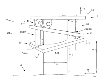
A first embodiment of the removable pile cap 10 of the present
invention is shown in FIGS. 2a-3d and is designed to be installed on a pile 1.
The
pile 1 has a longitudinal axis 11, an outside surface Is and an outside
diameter lo
(e.g. see FIG. 2f). The pile 1 is installed or driven substantially into the
ground G
with a portion of the pile 1 projecting above or out of the ground G; this
portion of
the pile 1 can then be referred to as the above-ground portion la, and the end
of
the pile 1 that projects above the ground can be referred to as the upper end
1u.
Preferably, the pile is a generally cylindrical or tubular member with a
substantially
circular cross-section (when said cross-section is taken along the plane that
is
perpendicular to the longitudinal axis 11).
More preferably the pile 1 is driven into the ground G in substantially
vertical manner, with its longitudinal axis 11 substantially along, or
parallel to, the
vertical plane V; see FIG. 2f. However, the pile 1 may also have other shapes
(e.g.
having a square cross-section, an octagonal cross-section or an H-shaped cross-
section) or be driven into the ground G with its longitudinal angle 11 at an
angle
offset from the vertical plane V. The pile 1 may be made of any suitable
material of
sufficient strength and durability to support a structure and load thereupon;
for
example, the pile 1 may be made of steel, wood or concrete.
The removable pile cap 10 comprises an end member 20 and at least
one pile member 30 (see, for example, the embodiment of figure 9). The end
6
CA 02926460 2016-04-08
member 20 is suitable to abut against, be placed on, and/or be supported by
the
pile's upper end lu, in a similar manner that the flat plate of steel of
traditional pile
caps is laid on top of a pile's upper end (e.g. see FIGS. 2f-6b). When end
member
20 is placed on the pile's upper end 1u, it can then also be referred to as a
top
member 20. The
terms "end member" and "top member" will be used
interchangeably herein.
The top member 20, once supported by the pile's upper end 1u, is
suitable to accept one or more structural foundation elements, so that the
load, or
downward force (i.e. substantially down along the vertical plane) of any such
structural foundational elements (and any structure placed thereupon) is then
substantially transmitted via top member 20 into the pile 1. The top member 20
preferably comprises a substantially planar steel plate or other planar member
of
suitably strong material. In one embodiment of the removable pile cap 10,
suitable
for a cylindrical pile 1 with an outside diameter lo of four inches (4"), the
top
member 20 is preferably a steel plate having width and a length of 200mm with
a
thickness of 12.7 mm.
In the embodiment of FIGS. 2a-3d the removable pile cap 10 has two
pile members, namely a first pile member 30 and a second pile member 30'. In
another embodiment (e.g. FIG. 9), the removable pile cap 10 has one pile
member.
In yet another embodiment (e.g. FIG. 10), the removable pile cap 10 has three
pile
members, namely a first, a second and a third pile member 30, 30', 30".
Generally
speaking, the greater the number of pile members 30 in a particular embodiment
of
7
CA 02926460 2016-04-08
a pile cap 10, the greater the amount of any upward forces (i.e. substantially
upward
along the vertical plane V and along a pile's longitudinal axis 11) that may
be
successfully handled by such embodiment of the pile cap 10 during operation;
assuming that all the other components and materials of the pile cap 10 are
likewise
suitable to handle such forces.
The at least one pile member 30 is suitable to be placed around or
fitted over the pile's upper end 1u and at least part of the pile's above
ground
portion la, when said member 30 is substantially maintained in a first
orientation 01
relative to the pile 1; e.g. see FIGS. 3a and 7a. The at least one pile member
30 is
also suitable to bind against, and maintain frictional engagement with, at
least part
of the pile's above ground portion 1 a, when said member 30 is substantially
maintained in a second orientation 02 relative to the pile 1; e.g. see FIG. 3b
and 8a.
In the embodiment of FIGS. 2a-3d the pile members 30, 30' preferably
comprises a substantially planar steel plate, or other planar member along a
plane
P, of suitably strong material and each further comprise an opening 32,32'
passage
or recess therein. Opening 32,32' is of such dimensions and shape such that it
is
suitable to accept the pile's upper end 1u and then be moved or slid over at
least
part of the pile's above ground portion la when the pile member 30, 30' is
maintained in a first orientation 01.
In one embodiment of the removable pile cap 10, suitable for a pile 1
with a substantially circular cross-section having an outside diameter lo of
four
inches (4"), the pile member 30 is a steel planar plate having width and a
length of
200mm, a thickness of 13 mm and a substantially centrally located and circular
8
CA 02926460 2016-04-08
opening 32,32' therethrough with a diameter of 110mm (or approximately 4.33
inches). As such, in said embodiment and assuming the pile 1 is driven into
the
ground G in substantially vertical manner, with its longitudinal axis 11
substantially
along, or parallel to, the vertical plane V, the pile member 30,30' will be in
the first
orientation 01 when its plane P is maintained substantially parallel to the
horizontal
plane H (e.g. see FIG. 3a) and will be in the second orientation 02 when its
plane P
is offset from the horizontal plane H (e.g. see FIG. 3b). A suitable amount of
offset
from the horizontal plane H, to place the pile member 30,30' of such
embodiment in
the second orientation is 15 degrees.
It will now also be understood that, when the pile 1 may be driven into
the ground G with its longitudinal axis 11 off-set from the vertical plane V,
the pile
member 30,30' will be in the first orientation 01 when its plane P is
maintained
substantially perpendicular to the pile's longitudinal axis 11; and the pile
member
30,30' will be in the second orientation 02 when its plane P is offset from
being
perpendicular to the pile longitudinal axis 11.
In another embodiment (not shown), suitable for a pile 1 with a
substantially square cross-section, each sides of the square cross-section
being
four inches (4") in length, the pile member 30 is preferably a steel planar
plate
having width and a length of 200mm, a thickness of 13 mm and a substantially
centrally located and a square opening 32 therethrough with each side of that
square opening being 110mm (or approximately 4.33 inches) in length.
9
CA 02926460 2016-04-08
The top member 20 and the one or more pile members 30, 30' are
connected or fastened together serially, with the top member 20 at a first end
12 of
the removable pile cap 10, with one of the at least one pile members 30, 30'
at a
second generally opposing end 14 of the pile cap 10 and with any remaining
pile
members being serially connected therebetween (e.g. see FIG. 2f). During
operation, the top member 20 and the one or more pile members 30, 30' are also
connected or fastened together in a generally tensile manner, i.e. so that at
least
some tensile or pulling force T that may be applied to a member at one end
(e.g. top
member 20 at first end 12) is transmitted through the removeable pile cap 10
to the
member at the opposing end (e.g. pile member 30' at second end 14; e.g. see
FIG.
2f). Preferably, the top member 20 and the one or more pile members 30, 30'
are
connected or fastened together serially in such a manner that any tensile or
pulling
force T will bias or move the one or more pile members 30, 30' into the second
orientation 02 (e.g. see FIG. 2f).
In the embodiment of FIGS. 2a-3d the top member 20 and pile
members 30 are connected or fastened together via pivoting hinge 40 and
tensile
members 50. Pivoting hinge 40 pivotally connects top member 20 to a first pile
member 30, allowing tensile forces to be transmitted between said members 20,
30.
The pivoting hinge 40 create a pivot point P1 where the first pile member 30
rotates
between position 01 into position 02 (see FIGS. 3a ¨ 3b). The pivoting hinge
40
also allows tensile forces to be transmitted between said members 20, 30.
CA 02926460 2016-04-08
With the top member 20 being supported by the pile upper end lu, the
first pile member 30 may be moved from position 01 into position 02, via the
pivot
40 (see FIGS. 3a ¨ 3b). When this is done, and member 30 is in position 02,
the
interior edge B or surface of opening 32 will frictionally engage with the
pile's
outside surface Is and lock the pile cap 10 onto the upper end 1u. Similarly,
any
additional pile members (e.g. 30' and 30") will likewise have an interior edge
B or
surface of their openings (e.g. 32') frictionally engage with the pile's
outside surface
Is when in position 02.
In this embodiment, pivoting hinge 40 comprises a first set of two legs
42 depending from the top member 20 towards the first pile member 30, and a
second set of two legs 44 depending from the first pile member 30 towards the
top
member 20. Each of the leg members have a substantially circular hole or
opening
400 therethrough, suitable to accept a bolt or hinge pin 46 therethrough, when
the
openings 40o of first and second sets of legs 42, 44 are aligned; see FIG. 2a -
2f.
Further in the embodiment of FIGS. 2a-3d the top member 20 and pile
members 30' are connected or fastened together via tensile members 50 which
comprise a pair of bolts 52 placed through a pair of bolt openings 20o in the
top
member 20 and through a corresponding pair of bolt openings 300' in pile
member
30'. Said bolt openings 20o, 30o' in each of top member 20 and pile member 30'
are of sufficient size to accept the shank 52s of the bolt therethrough, but
prevent
passage of the bolt's head 52h or any nut 54 therethrough. Bolts 52 may also
pass
or slide through pile member 30, by way of a pair of bolt opening 30o therein,
11
CA 02926460 2016-04-08
sufficiently dimensioned to accept the shank 52s of the bolt therethrough, but
also
sufficiently dimensioned prevent passage of the bolt's head 52h or any nut 54
therethrough. Nuts 54 are utilized in a conventional manner to secure bolts 52
and
allowing tensile forces T to be transmitted between said the top member 20 at
first
end 12 and the pile member 30' at second end 14. The tensile members 50 (with
their shanks 52) positioned though opening 30' in pile member 30' create a
second
pivot point P2 where the second pile member 30' rotates between position 01
into
position 02 (see FIGS. 3b ¨ 3c).
To unlock and remove the pile cap 10 from the pile 1, all pile members
(30, 30', 30") can be moved to position 01, thereby becoming free to slide
along
pile 1.
Preferably, the removable pile cap 10 further comprises securing or
lock means 60 that can be used to maintain the one or more pile members 30,
30'
into the second orientation 02. In the embodiment of FIGS. 2a-3d securing
means
60 comprises one or more nuts 60n on bolts 52 that can be threaded along shank
52s and, along with hinge 40, maintain pile member 30 in the second
orientation
(e.g. see FIGS. 2f, 3d). In the embodiment of FIGS. 2a-3d securing means 60
further comprises a steel wedge member 62 that can be positioned between pile
member 30 and pile member 30', thereby maintaining pile member 30' in the
second orientation (e.g. see FIGS. 2f, 3d). Preferably, securing means 60
further
comprises elevation or bump 63 on pile member 30' to assist with maintaining
12
CA 02926460 2016-04-08
wedge member 62 positioned between pile member 30 and pile member 30' (e.g.
see FIG. 3c and 3d). Alternatively, wedge member 62 may be secured in place
via
a quick tack weld.
Advantageously, when the one or more pile members 30, 30' are in
the second orientation 02, and the top member 20 and the one or more pile
members 30, 30' are fastened together serially, the removable pile cap 10 is
secured onto the pile 1 without the need for welding and can be used on piles
made
of a variety of materials (e.g. steel, concrete or wood). As such, the second
orientation 02 can also be referred to as the secured or locked orientation of
the
pile cap 10, in that the pile cap 10 will then be secured onto the pile 1. In
particular,
any load forces (typically downward) will simply be transmitted into the pile
1 via top
member 20. Any forces that opposes the load (i.e. typically upward) will,
assuming
they overcome such a load, simply result in maintaining the pile members 30,
30' in
the second orientation 02 (and further engaging any interior edge B of opening
32
with the pile's surface Is, thereby even further securing the pile cap 10 to
the pile
1). Any forces that may be lateral to the pile's longitudinal axis 11 (i.e.
typically
sideways forces) will be countered by the pile members 30, 30' being placed
around
the pile 1.
More advantageously, by adapting the dimensions of the opening 32
in a pile member 30 to correspond to the outside dimensions of a pile 1 (e.g.
circular
opening 32 for a pile with a circular cross-section; or square opening 32 for
a pile
13
CA 02926460 2016-04-08
with a square cross-section), the removable pile cap 10 can be used and
installed
on a variety of pile shapes. Even more advantageously, and as will now be
appreciated by those skilled in the art, it will take only a small amount of
time and
effort to place a pile cap 10 over a pile 1 (e.g. FIG. 3a), move the pile
members 30,
30' into the second orientation 02 (e.g. FIGS. 3b ¨ 3c) and engage the lock
means
60 (e.g. FIG. 3d). The inventor estimates that a pile cap 10 can be positioned
and
secured on a pile 1 within 15 minutes for an experienced installer; thereby
saving
the costs normally associated with welding a cap onto a pile.
Still more
advantageously, the pile cap 10 of the present invention can be installed even
when
there is limited space to work and without having to dig out some of the
surrounding
dirt to obtain sufficient clearance for a welder to work.
Other Embodiments:
In FIGS. 4a ¨ 4e another embodiment of the invention 10 is shown.
This embodiment is similar to the embodiment of FIGS. 2a-3d, but instead of
the top
member 20 and pile members 30' being connected together via tensile a pair of
bolts 52 a second pivoting hinge 40' pivotally connects first pile member 30
to
second pile member 30' (with top member 20 similarly being connected to first
pile
member 30 vial first pivoting hinge 40), allowing tensile forces to be
transmitted
between said members 20, 30, 30'.
14
CA 02926460 2016-04-08
In FIGS. 5a ¨5c yet another embodiment of the invention 10 is shown.
This embodiment is similar to the embodiment of FIGS. 4a ¨ 4e, but the
securing
means 60 comprises rod members 66, 66' that may be removably secured between
top member 20 and first pile member 30, and between first pile member 30 and
second pile member 30'; as more clearly shown in FIGS. 5a ¨5c.
In FIGS. 6a ¨ 6e yet another embodiment of the invention 10 is
shown. This embodiment is similar to the embodiment of FIGS. 2a-3d, but
instead
of securing means 60 comprising a wedge member that can be positioned between
pile member 30 and pile member 30' (to maintain pile member 30' in the second
orientation 02), securing means 60 instead comprises wedge member 68 that is
insertable in opening 32' so as to wedge between pile member 30' and the pile
1
and thereby maintain pile member 30' in the second orientation 02. In yet
another
embodiment (e.g. FIG. 10), where the pile cap 10 is expected to remain
installed on
the pile 1 for the long term, the securing means is a quick tack weld W that
is
applied between pile member 30 and pile 1 at approximately the same location
where wedge member 68 is placed in the embodiment of FIGS. 6a ¨ 6e.
In FIG. 9 another embodiment of the invention 10 is shown. This
embodiment is similar to the embodiment of FIGS. 2a-3d, but instead of
comprising
two pile members, the pile cap 10 comprises a single pile member 30. Further,
as
in the embodiment of FIG. 6a ¨ 6e, securing means 60 comprises wedge member
CA 02926460 2016-04-08
68 that is insertable in opening 32 so as to wedge between pile member 30 and
the
pile 1 and thereby maintain pile member 30 in the second orientation 02.
In FIG. 10 yet another embodiment of the invention 10 is shown. This
embodiment is similar to the embodiment of FIGS. 2a-3d, but instead of
comprising
two pile members, the pile cap 10 comprises a three pile members 30, 30' and
30".
Advantageously, the plurality of pile members 30, 30' and 30", once placed in
the
second orientations 02, provide additional biting edges B to allow said pile
members 30, 30' and 30" to bind against, and maintain frictional engagement
with,
at least part of the pile's above ground portion la. More advantageously, such
additional pile members 30, 30' and 30" and biting edges B provide for
increased
resistance to any upward forces that may act on the pile cap 10 (and any
structural
foundation elements thereon), such as in cases where buildings may be exposed
to
high wind loads. In this embodiment, the securing means 60 is a quick weld W
that
is applied between pile member 30 and pile 1 at approximately the same
location
where wedge member 68 is placed in the embodiment of FIGS. 6a ¨ 6e.
In FIG. 11 yet another embodiment of the invention 10 is shown. This
embodiment is similar to the embodiment of FIGS. 2a-3d, but instead of
securing
means 60 comprising a wedge member that can be positioned between pile
member 30 and pile member 30' (to maintain pile member 30' in the second
orientation 02), securing means 60 instead comprises one or more nuts 60n on
bolts 52 that can be threaded along shank 52s, one or more nuts 60n on set
screw
16
CA 02926460 2016-04-08
69 (with set screw 69 depending from member 30 and passing through an opening
(not shown) in member 30') and hinge 40, to maintain pile member 30 in the
second
orientation.
In FIGS. 12a ¨ 12f yet another embodiment of the invention 10 is
shown. This embodiment is similar to the embodiment of FIG. 11, but in this
embodiment the pivoting hinge 40 comprises two hinge members or legs 401 which
project from top member 20 towards and through pile member 30, via
corresponding leg passages 30p provided on pile member 30. Leg passages 30p
are of sufficient size to accept hinge legs 401 therethrough and to allow pile
member
30 to pivot therealong between the first and second orientations. Once passed
through leg passages 30p, the distal ends of the hinge legs 401 are preferably
connected via a bolt and nut assembly 40b. Leg passages 30p are of such size
and
dimensions to prevent passage of the bolt and nut assembly 40b therethrough,
effectively capturing pile member 30 on hinge legs 401 once bolt and nut
assembly
40b is mounted to the distal ends of the hinge legs 401¨ see FIGS. 12e and
12F.
17
CA 02926460 2016-04-08
Example
In one embodiment of the removable pile cap 10, similar to the
embodiment of FIGS. 2a-3d, the pile cap 10 was secured on a cylindrical pile 1
with
an outside diameter lo of four inches (4"), in a manner similar to that shown
in
FIGS. 2f and 3d, with the pile members 30, 30' in the second orientation 02.
In this
embodiment, the top member 20 was a CAN/CSA G40.21 Grade 300W steel plate
having width and a length of 200mm with a thickness of 12mm, with the pile
members 30, 30' and the hinge's legs 42,44 likewise being made of 12 mm thick
steel, and with bolts 46 and 52 being steel 3/8" bolts. Holes 32, 32' were
substantially centrally located and circular openings having a diameter of 110
mm.
Once the pile cap 10 was in the secured orientation, an increasing tension
force T
was applied to the top of the top member 20, causing the interior surfaces and
edges B of holes 32, 32' to frictionally engage the outside surface Is of pile
1. At a
tension force T of 26kN, it was observed that the pile cap 10 remained
substantially
in the secured orientation with only 8mm of deformation occurring, this being
a
combination of the pile members 30, 30' biting into the pile 1, as well as
some minor
bolt 46, 52 deflection. As the tension force T increased, to a tension T of
59.7 kN,
bolt 46 in the hinge 40 sheared. A final 18mm deformation of the pile cap 10
was
observed just prior to bolt 46 shearing.
18
CA 02926460 2016-04-08
Those of ordinary skill in the art will appreciate that various
modifications to the invention as described herein will be possible without
falling
outside the scope of the invention. In the claims, the word "comprising" is
used in
its inclusive sense and does not exclude other elements being present. The
indefinite article "a" before a claim feature does not exclude more than one
of the
features being present.
19