Note: Descriptions are shown in the official language in which they were submitted.
CA 02926467 2016-04-04
WO 2015/051346
PCT/US2014/059204
LIGHT REPLACING APPARATUS FOR REPLACING BULBS IN STREET LAMPS
CROSS-REFERENCE TO RELATED APPLICATIONS
[0001] This
application claims priority to U.S. Patent Application No. 14/506,467, filed
October 3, 2014, entitled LIGHT REPLACING APPARATUS FOR REPLACING BULBS
IN STREET LAMPS (Atty. Dkt. No. TNBT-32366), and to U.S. Provisional
Application No.
61/886,777, filed October 4, 2013, entitled LIGHT REPLACING APPARATUS FOR
REPLACING BULBS IN STREET LAMPS (Atty. Mt. No. TNBT-31746), the
specifications of which are incorporated herein in their entirety.
TECHNICAL FIELD
[0002] The
present invention pertains in general to lighting apparatuses, and more
particularly to a technique for replacing a bulb on a high lamp pole.
1
CA 02926467 2016-04-04
WO 2015/051346
PCT/US2014/059204
BACKGROUND
[0003] Light
poles have lamps that are between 20 and 30 feet from the ground. In order
to change a lamp, which sometimes might be changed once or twice a year, it is
necessary to
rent a "cherry picker" and then raise the individual up to the level of the
lamp to gain access
thereto. This can be quite expensive if a single bulb has to be replaced, and
one waits for
multiple bulbs to be replaced in order to rent the equipment.
2
CA 02926467 2016-04-04
WO 2015/051346
PCT/US2014/059204
BRIEF DESCRIPTION OF THE DRAWINGS
[0004] For a more complete understanding, reference is now made to the
following
description taken in conjunction with the accompanying Drawings in which:
[0005] Fig. 1 illustrates a diagrammatic view of a prior art method for
installing light
poles;
[0006] Fig. 2 illustrates a general diagram of the use of the bulb
replacement device of
the present embodiment;
[0007] Fig. 3 illustrates a cross-sectional detail of the operation of
removing a bulb with
the apparatus of the present embodiment;
[0008] Fig. 4 illustrates a detail of the removal device;
[0009] Fig. 5 illustrates a cross-sectional view of the apparatus for
inserting a new bulb
into the lamp device;
[0010] Fig. 6 illustrates a diagrammatic view of the insertion apparatus;
[0011] Fig. 7 illustrates a further perspective view of the insertion
device;
[0012] Fig. 8 illustrates a cross-sectional top view of the insertion
device;
[0013] Fig. 9 illustrates a series of views for the bulb holder;
[0014] Fig. 10 illustrates multiple views of the engaging ring;
[0015] Fig. 11 illustrates multiple views of the actual apparatus stored on
the top of the
pole for containing the bulb holder after insertion or prior to extraction;
[0016] Fig. 12 illustrates multiple views of the housing that fits on the
top of the pole;
and
3
CA 02926467 2016-04-04
WO 2015/051346
PCT/US2014/059204
[0017] Fig. 13
and Fig. 13A illustrates a diagrammatic view of inserting the bulb into the
holder.
4
CA 02926467 2016-04-04
WO 2015/051346
PCT/US2014/059204
DETAILED DESCRIPTION
[0018]
Referring now to the drawings, wherein like reference numbers are used herein
to
designate like elements throughout, the various views and embodiments of a
light replacing
apparatus for replacing bulbs in street lamps are illustrated and described,
and other possible
embodiments are described. The figures are not necessarily drawn to scale, and
in some
instances the drawings have been exaggerated and/or simplified in places for
illustrative
purposes only. One of ordinary skill in the art will appreciate the many
possible applications
and variations based on the following examples of possible embodiments.
[0019]
Referring now to Fig. 1, there is illustrated a prior art installation method
for a
lamp. Illustrated is a lamp pole 102 with a lamp 104 disposed on the upper end
thereof This
lamp pole 102 is between 20 and 30 feet in height. In order to change the
lamp, which is
illustrated in a detail where the bulb 104 is disposed within a holder 106,
some type of
machine such as a cherry picker or an elevator 108 is required. The elevator
has a box 110
disposed on the top thereof that can be elevated high enough for an individual
sitting in the
box 110 to change the bulb 104. This requires the renting of the elevator 108
or a cherry
picker to change a single bulb. If multiple lamp poles are provided in a
parking lot, for
example, and only a single bulb goes out, it is not cost-efficient to change
such.
[0020]
Referring now to Fig. 2, there is illustrated a diagrammatic view of an
embodiment of the present disclosure. A lamp pole 202 is provided,
illustrating that there is
an access hole 204 disposed on the lower side thereof A flexible fiberglass
rod 206 can be
inserted upward into the lamp pole all the way to the top to access a lamp
holder 208. As will
be described herein below, this lamp holder 208 is utilized to hold a bulb
210, which can be
inserted into the holder 208 with the flexible fiberglass rod 206, or
extracted therefrom. This
enables an individual to replace a bulb by removing the bulb with the
fiberglass rod and then
inserting another bulb therein without the need for rental of expensive
equipment.
[0021]
Referring now to Fig. 3, there is illustrated a diagrammatic view of the
embodiment of Fig. 2. A housing 302 is provided that is disposed at the upper
end of the
lamp pole and comprises the housing 208 in Fig. 2. This housing has disposed
therein some
cantilevered members 306 that are operable to swivel into position. There is
provided a
removal lamp holder 308, which can be pushed upward through the members 306,
which
pivot out of the way and then will fall into place and support the lamp holder
308 on the
CA 02926467 2016-04-04
WO 2015/051346
PCT/US2014/059204
lower surface thereof The bulb and lamp holder 308 can be removed by pushing
an
extraction apparatus 310 upward into the opening in the housing 302 and
upward, which will
cause the pivoting members 306 to move upward, while the lamp holder 308 is
also moved
upward such that the edges of the lamp holder 308 will clear the distal edges
of the pivoting
members 306. This allows the lamp holder 308 to fall down into the extraction
apparatus
310, and then be extracted therefrom by pulling the fiberglass rod downward.
In general, the
holder 308 is held there by gravity. An electrical cord 318 extends downward
from the lamp
210 through the holder 308.
[0022]
Referring now to Fig. 4, there is illustrated a detail of the extraction
device. This
is basically a circular member having a slot 404 disposed in one side thereof
to allow the
extraction device 310 to be disposed about the cord 318. There is a base 406
on the bottom
thereof which has a circular cutout 408 disposed therein to receive the cord.
The outer
surfaces of the housing 310 will substantially coincide with the circular
construction of the
housing 302. The flexible rod 206 extends upward and attaches to the base 406.
[0023]
Referring to Fig. 5, there is illustrated diagrammatic detail of inserting a
lamp
holder 308 back into the housing 306. An insertion apparatus 502 is provided
that is operable
to be urged against the lower end of the lamp holder 308. There is a
protrusion 506 that is
disposed on the lower surface of the lamp holder 308 that is operable to be
inserted into the
insertion device. The insertion device 502 is operable to urge the lamp holder
308 upwards
until it contacts the pivoting members 306 to urge them outward, and then the
lamp holder
308 is urged above the distal edges of the pivoting members 306 such that they
will pivot
downward to contact the bottom surface of the lamp holder 308 such that, when
the insertion
device is pulled downward, the lamp holder 308 will remain within the housing
302 held
upwards therein by the pivoting members 506 on the distal ends thereof
[0024]
Referring now to Fig. 6, there is illustrated a diagrammatic view of the lamp
holder 308 disposed on the insertion device 502. The flexible rod 206 (there
being one
flexible rod associated with the insertion device and one with the extraction
device, but for
simplicity purposes, the same numeral will be used for both) is attached to
the bottom of the
surface of the insertion device 502.
6
CA 02926467 2016-04-04
WO 2015/051346
PCT/US2014/059204
[0025] Fig. 7
illustrates a detail which shows that the insertion device is comprised of an
outer cylindrical member 702 with a slot 704 disposed therein and an interior
cylindrical
member 708 with a slot 710 disposed therein. The interior cylindrical member
708 has an
outer diameter that is substantially the same as the interior cylindrical
diameter of the outer
cylinder 702 such that, when it is rotated, the two slots 704 and 710 will
oppose each other
and they will enclose the wire, as illustrated in the detail of Fig. 8. The
operation is to insert
the wire through the insertion apparatus and then close the inner cylinder
therearound, and
then insert it upward until it contacts the base of the holder 308 with the
protrusion 506
extending downward therein. The protrusion 506 can have a diameter that is
almost the same
as the inner diameter of the interior cylinder 708.
[0026]
Referring now to Fig. 9, there is illustrated a series of views of the lamp
holder
308. The lamp holder 308 has a receptacle 902 for the bulb 210 and an upper
cylindrical
surface 904 that is smaller than a lower cylindrical surface 906. The lower
cylindrical surface
is disposed on another flat thin surface having a diameter that is larger than
the diameter of
the lower cylindrical member 906, this being a cylindrical flat member 910.
This member
910 provides an edge on the lower end thereof There will be provided the
protrusion 506
extending downward therefrom.
[0027]
Referring now to Fig. 10, there is illustrated a diagrammatic view of an
engaging
ring 1001 that is operable to be disposed in a cavity 1101 in the housing 302
illustrated in
Fig. 11. This engaging ring has a lower outer ring 1002 that is substantially
the same
diameter as the interior of the housing 302 with a hole 1004 disposed
therethrough and an
upper cylindrical area therearound. The detail of Fig. 12 illustrates the
interaction. The
housing of Fig. 11 has an upper member 1102 disposed in the upper end thereof
with an
opening 1104 disposed therein. This is above the cavity 1101. The opening 1004
is operable
to receive the lamp holder 308. There are also provided an extending ring 1108
that extends
outward in an arcuate manner. This is operable to engage the outer edges of
the surface 1002
of the engaging ring 1001. It can be seen that, in Fig. 12, the engaging ring
1001 is disposed
within the cavity and held away from the surface 1006 by springs 1202.
Therefore, it is
urged downward.
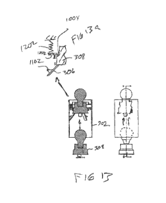
[0028] When the
lamp, as illustrated in Fig. 13, and the holder 308 are inserted upward
therethrough, the pivoting members 306 disposed about a pivot point 1102 on
the outer edges
7
CA 02926467 2016-04-04
WO 2015/051346
PCT/US2014/059204
of the housing 302 are inserted upward, the pivoting member 306 will pivot
outward and
allow the lamp holder 308 to extend upward through the opening with the
beveled surface,
surface 920, between the upper cylindrical member 308 and the lower
cylindrical member
906 of the lamp holder 308 will have a diameter approximately equal to the
interior diameter
of the hole 1004 in the engaging ring 1001. This will cause it to urge the
engaging ring
upward against the spring such that, when the insertion device is removed, the
lamp holder
will be urged downward against the distal ends of the pivoting devices 306.
This is
illustrated in a detail on Fig. 13A.
[0029] It
should be understood that the drawings and detailed description herein are to
be
regarded in an illustrative rather than a restrictive manner, and are not
intended to be limiting
to the particular forms and examples disclosed. On the contrary, included are
any further
modifications, changes, rearrangements, substitutions, alternatives, design
choices, and
embodiments apparent to those of ordinary skill in the art, without departing
from the spirit
and scope hereof, as defined by the following claims. Thus, it is intended
that the following
claims be interpreted to embrace all such further modifications, changes,
rearrangements,
substitutions, alternatives, design choices, and embodiments.
8