Note: Descriptions are shown in the official language in which they were submitted.
CA 02926784 2016-04-07
WO 2015/057246 PCT/US2013/068754
Improved Air-Assisted Separation System
Background
Fluidized-bed or teeter-bed separation systems are used for classification and
density
separation within the mining industry. The metallurgical performance and high
capacity of these
separation systems make them ideal for feed preparation prior to flotation
circuits. It has been
found that when this type of separation system implements a fluidization flow
with the addition
of air bubbles, performance can be improved beyond that achieved by systems
using only water.
This variety of separator is called an air-assisted separation system. These
devices are typically
controlled using two basic operating parameters: fluidization flow rate and
fluidized bed level.
What is presented are improvements to an air-assisted separation system,
incorporating various
novel features, that further enhance the separation process.
Summary
What is presented is a separation system for partitioning a plurality of
particles contained
in a slurry. The particles are influenced by a fluidization flow, which
comprises teeter water, gas
bubbles, and a fluidized bed. The separation system comprises a separation
tank, a slurry feed
distributor, a fluidization flow manifold, a gas introduction system, and an
underflow conduit all
arranged to create the fluidized bed in the separation tank by introducing the
slurry through the
slurry feed distributor and allowing the slurry to interact with the
fluidization flow from the
fluidization flow manifold. The separation tank has a launder for capturing
particles carried to
the top of the separation tank. The gas introduction system is configured to
optimize the gas
bubble size distribution in the fluidization flow. The gas introduction system
comprises a gas
introduction conduit and a bypass conduit for a flow of teeter water to bypass
the gas
1
CA 02926784 2016-04-07
WO 2015/057246 PCT/US2013/068754
introduction conduit. The gas introduction system can be adjusted to optimize
the gas bubble size
distribution by modulating the flow of teeter water through the gas
introduction conduit. The gas
introduction conduit and the bypass conduit converge to create the
fluidization flow. The volume
of fluidization flow is controlled by modulating the flow through said gas
introduction system.
In some embodiments of the separation system, a pressure reading apparatus is
arranged
and configured to measure the density of the fluidized bed. In some
embodiments the pressure
reading apparatus comprises two pressure sensors to measure the density of the
fluidized bed, or
a differential pressure transmitter configured to measure the density of the
fluidized bed. In some
embodiments a density indicating controller is used to control the gas
introduction system and
the underflow conduit and to adjust the density and level of the fluidized bed
based on
calculations performed by the density indicating controller based on signals
from the pressure
reading apparatus.
Some embodiments of the separation system comprise a slurry aeration system
for
aerating the feed slurry. Some of these embodiments comprise a sparging
apparatus for aerating
the fluidization water. Other embodiments of the separation system further
comprise a chemical
collector or a surfactant introduced into the fluidization flow to condition
the particles in the
slurry or to facilitate aeration of the fluidization flow.
Those skilled in the art will realize that this invention is capable of
embodiments that are
different from those shown and that details of the devices and methods can be
changed in various
marmers without departing from the scope of this invention. Accordingly, the
drawings and
descriptions are to be regarded as including such equivalent embodiments as do
not depart from
the spirit and scope of this invention.
2
CA 02926784 2016-04-07
WO 2015/057246 PCT/US2013/068754
Brief Description of Drawings
For a more complete understanding and appreciation of this invention, and its
many
advantages, reference will be made to the following detailed description taken
in conjunction
with the accompanying drawings.
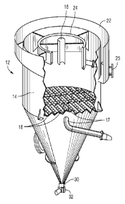
Fig. 1 shows a schematic view of the separation system;
Fig. 2 is a perspective view of a fluidized bed separation cell;
Fig. 3 is a cross-section of a separation tank showing the components of a
typical
fluidized bed;
Fig. 4A is a cross-section of a separation tank showing the components of a
less-dense
fluidization bed; and
Fig. 4B is a cross-section of a separation tank showing the components of a
more-dense
fluidization bed.
Detailed Description
Referring to the drawings, some of the reference numerals are used to
designate the same
or corresponding parts through several of the embodiments and figures shown
and described.
Variations of corresponding parts in form or function that are depicted in the
figures are
described. It will be understood that variations in the embodiments can
generally be interchanged
without deviating from the invention.
Separation systems implementing fluidized beds (also called a teeter bed or a
teeter water
bed or a fluidized teeter bed) are commonly used in the minerals industry to
partition a plurality
of particulate mineral species contained in a liquid suspension or slurry.
These slurries consist of
a mixture of valuable and less valuable mineral species. Separation systems
that implement an
3
CA 02926784 2016-04-07
WO 2015/057246 PCT/US2013/068754
aerated fluidization flow (teeter water with gas introduced to form gas
bubbles) and a fluidized
bed are called air-assisted separation systems. An example of an air-assisted
separation system as
described herein is the HYDROFLOATTm, manufactured by Eriez Manufacturing
Company of
Erie, Pennsylvania. As shown in FIGs. 1 through 3, the air-assisted separation
system 10
comprises a fluidized bed separation cell 12 with an associated gas
introduction system 38, slurry
aeration system 62, and pressure reading apparatus 70, each discussed in more
detail below. As
best understood by comparing Figs. 1 and 2, slurry is fed into a separation
tank 14 through a
slurry feed distributor 16, generally located in the upper third of the
separation tank 14. The
particulate mineral matter in the slurry moves downwards countercurrent to an
upward flow of
teeter water. The teeter water is fed into the separation tank 14 through a
fluidization flow
manifold 18 generally located around the center of the separation tank 14 and
connected to an
inflow conduit 17.
Comparing Figs. 2 and 3, as slurry is introduced into the upper section of the
separation
tank 14 through the slurry feed distributor 16, the upward flow of teeter
water and gas bubbles
collide with the downward flowing slurry, causing the particles in the slurry
to separate as a
result of some of the particles in the slurry selectively attach to the gas
bubbles. The particles that
are fine/light are hydraulically carried upward by the flow of teeter water
and those particles
attached to the gas bubbles float to the top, staying within an overflow layer
20 to eventually be
carried over the top of the separation tank 14. After being carried over the
top of the separation
tank 14, these particles flow into either an external overflow launder 22 or
an internal overflow
launder 24 and are carried out of the system by an overflow conduit 25 that
drains both overflow
launders 22 and 24.
4
CA 02926784 2016-04-07
WO 2015/057246 PCT/US2013/068754
The particles that are more coarse/dense, and those that did not attach to the
gas bubbles
that have sufficient mass to settle against the upward flow of teeter water,
fall downwardly
through the separation tank 14 and form a fluidized bed 26 of suspended
particles. The fluidized
bed 26 acts as a dense medium zone within the separation tank 14. Within the
fluidized bed 26,
small interstices create high interstitial liquid velocities that resist the
penetration of the particles
that could settle against the upward flow of teeter water, but that are too
fine/light to penetrate
the already formed fluidized bed 26. As a result, these particles will
initially fall downward until
they contact the fluidized bed 26 and are forced back upwardly to accumulate
in the overflow
layer 20. These particles are eventually carried to the top of the separation
tank 14 and end up in
one of the overflow launders 22 or 24.
The particles that are too coarse/dense to stay above the fluidized bed 26 and
those that
do not attach to a gas bubble will eventually pass down through the fluidized
bed 26 and into an
underflow layer 28. Once in the underflow layer 28, these particles are
ultimately discharged
from the underflow layer 28 through an underflow conduit 30. An underflow
valve 32 regulates
the amount of coarse/dense and unattached particles discharged from the
separation tank 14. The
type of underflow valve 32 is dependent on the application and can vary from a
rubber pinch
valve to an eccentric plug valve, but it should be understood that any under
flow valve 32 that
can adequately regulate the discharge of coarse/dense particles may work.
Hindered-bed separators segregate the particles that are fine/light from those
that are
course/dense based on their size and specific gravity. The separation effect
is governed by hindered-
settling principles, which has been described by numerous equations including
the following:
d2 (Omax ¨ 0)13 (Ps P f)
=
Ut
1877(1 + 0.15Re =687)
CA 02926784 2016-04-07
WO 2015/057246 PCT/US2013/068754
where Ut is the hindered-settling velocity of a particle (m/sec), g is the
acceleration due to gravity
(9.8m/sec2), d is the particle size (m), Ps is the density of the solid
particles (kg/m3), pf is the density
of the fluidizing medium (kg/m3), i is the apparent viscosity of the fluid
(kg=m-1 .s-1), 4 is the
volumetric concentration of solids, 46aõ is the maximum concentration of
solids obtainable for a given
material, and 13 is a function of Reynolds number (Re). By inspection of this
equation one having
ordinary skill in the art can determine that the size and density of a
particle greatly influences how that
particle will settle within a hindered settling regime.
One having ordinary skill in the art can also see that aerating the teeter
water, by introducing
gas (i.e., air) into the flow of the teeter water to create gas bubbles, will
affect the settling
characteristics of the particles that attach to these gas bubbles. The
fluidization flow of the air-assisted
separation system is aerated by introducing gas into the flow of teeter water
prior to entering the
separation tank 12. Therefore, for known slurry compositions, the fluidization
flow can be modulated
to optimize gas bubble interactions with target particles and carry these
target particles to the top of the
separation tank 12 for removal.
As shown in Fig. 1, a gas introduction system 34 is used to optimize the gas
bubble
introduction to the fluidization flow. The gas introduction system 34
comprises two conduits arranged
in parallel, a gas introduction conduit 36 and a bypass conduit 38. Both
conduits are located
downstream from a teeter water supply line 40, which provides the supply of
teeter water to the gas
introduction system 34, and upstream from the inflow conduit 17 and
fluidization flow manifold 18.
When the flow of teeter water enters the gas introduction system 34, it splits
apart so that a first
portion of the flow of teeter water flows through the gas introduction conduit
36 and a second portion
of teeter water flows through the bypass conduit 38.
6
CA 02926784 2016-04-07
WO 2015/057246 PCT/US2013/068754
The first portion of the flow of teeter water is aerated in the gas
introduction conduit 36.
A gas introduction point 44 introduces gas into the flow of teeter water to
generate bubbles as the
flow of teeter water passes through the gas introduction conduit 36. A
sparging apparatus 42
sparges, or breaks up, the generated gas bubbles into smaller gas bubbles. Any
type of sparging
apparatus that can sparge the bubbles sufficiently may be used, such as, but
not limited to, an in-
line static mixer or high shear sparging system. Generally, the sparging
effect of the sparging
apparatus 42 varies with the flow rate of teeter water through it. The gas
introduction conduit 36
also comprises a flow meter 46 to monitor the rate of flow of teeter water
through the gas
introduction conduit 36. Typically, this flow meter 46 is located upstream of
the gas introduction
point 44 to reduce the interference of gas bubbles on the operation of the
flow meter 46.
The gas introduction system 34 may combine other types of systems to introduce
gas and
sparge bubbles than have been shown. In FIG 1, the gas introduction point 44
is shown to
provide pressurized gas to the system. It will be understood that systems that
do not need
condensed gas to operate may be used instead, such as aspirators that utilize
the Venturi effect to
draw gas into the flow of teeter water.
The bypass conduit 38 allows the second portion of the flow of teeter water to
bypass the
gas introduction conduit 36, without interfering with the efficient operation
of the sparging
apparatus 42. The bypass conduit 38 comprises an automatic valve 47, which
controls the
volume of flow passing through the bypass conduit 38. At the end of the gas
introduction system
38 when both the first and second portions of the flow of teeter water
converge, the portions
combine to create the fluidization flow that enters into the fluidized bed
separation cell 12.
When the separation system 10 is in use, the flow meter 46 communicates with a
computing mechanism 49, which communicates with and adjusts the automatic
valve 47 to
7
CA 02926784 2016-04-07
WO 2015/057246 PCT/US2013/068754
throttle the flow of teeter water passing through the bypass conduit 38. This
approach maintains
a constant flow of teeter water through the gas introduction conduit 36. The
teeter water supply
line 40 also incorporates a control system 48 which consists of a flow
measurement device 78, a
flow control valve 80 and a density indicating controller 76, discussed below.
The control system
48 modulates the volume of flow of teeter water before entering the gas
introduction system 34,
which will subsequently optimize the volume of fluidization flow entering into
the fluidized bed
separation cell 12.
In certain applications, air-assisted separation systems use reagents, such as
chemical
collectors, to condition particles to improve attachment of target particles
to the gas bubbles.
Surfactants are also used to facilitate the general creation of gas bubbles.
To introduce these reagents,
prior art separation systems (not shown) typically incorporate a plurality of
stirred-tank conditioners
(not shown). The stirred-tank conditioners, however, consume a great deal of
energy and occupy
significant floor space. As such, there is an incentive within the field to
achieve the goal of
introducing reagents into separation systems while consuming less energy and
space than would be
needed to incorporate a plurality of stirred-tank conditioners.
Referring back to FIG. 1, it has been found that reagents can be introduced
into the separation
system 10 simply by being injected into the teeter water supply line 40 using
a collector pump 58 or a
surfactant pump 60. As the reagent is introduced into the teeter water supply
line 40, it travels with the
teeter water to the gas introduction system 34. Injecting the reagents into
the gas introduction system
34 causes them to directly and completely mix into the fluidization flow prior
to entering the
separation tank 14. It has also been found that mixing the reagents and
fluidization flow through the
gas introduction system 34 in this manner causes a more evenly distributed and
intimate mixture than
one created through the use of a stir tank.
8
CA 02926784 2016-04-07
WO 2015/057246 PCT/US2013/068754
It has also been found that pre-aeration of the slurry within the slurry feed
distributor 68
allows for contacting of the gas bubbles and particles entering the separation
tank 12. To accomplish
pre-aeration, a slurry aeration system 62 is incorporated into the feed
introduction system 16. The
slurry aeration system 62 introduces aerated water into the slurry while still
traveling through the
slurry feed piping 16 or directly into the slurry feed distributor 68. The
slurry aeration system 62
comprises two lines, a water introduction line 64 and an air introduction line
67. The water and air
pass through a sparging apparatus 42 and is subsequently discharged into the
slurry feed piping 16 or
the slurry feed distributor 68. The addition of air into the feed slurry
enhances the flotation kinetics by
reducing the contacting time required in the separation tank 12.
It has also been found that if the density of the fluidized bed 26 is
manipulated, it is
possible to influence the type of the particles that flow through the
fluidized bed 26. As shown in
FIGs. 4A and 4B, when the fluidized bed 26 becomes denser, particles that are
coarser/denser
can be held within the fluidized bed 26 without falling downward into the
underflow layer 28.
The opposite effect occurs when the fluidized bed 26 is more dilute and less
dense. As the
fluidized bed 26 becomes less dense, particles that are fine/light will fall
downward through the
fluidized bed 26 and into the underflow layer 28. Given that the separation
system can make
separations based on the size and/or density of the particles within the
slurry, it is beneficial to
adjust the density of the fluidized bed 26 so as to control the operation of
the fluidized bed
separation cell 12.
Referring back to FIG. 1, to adjust the fluidized bed 26, a pressure reading
apparatus 70
is installed within the fluidized bed separation cell 12 to gauge the pressure
within the fluidized
bed 26 and relay that information to a computing mechanism (not shown), which
calculates the
9
CA 02926784 2016-04-07
WO 2015/057246 PCT/US2013/068754
density of the fluidized bed 26. The computing mechanism is typically a
programmable logic
controller, but any apparatus able to calculate the density of the fluidized
bed 26 may work.
At least two pressure transducers are placed within the separation tank 14, an
upper
pressure transducer 72 and a lower pressure transducer 74. The pressure
transducers 72 and 74
are typically individual pressure sensors that have internal strain gauges
used to measure the
pressure created by the mixture of fluid and slurry surrounding the pressure
sensors within the
separation tank 14. Both the upper pressure transducer 72 and a lower pressure
transducer 74 are
configured to read the density of the fluidized bed 26 immediately surrounding
their position
within the separation tank 14. It should be noted that even though pressures
transducers with
internal strain gauges are commonly used, one of ordinary skill in the art
will see that any device
able to read and convey the pressure of the surrounding pressure of the
fluidized bed may work,
such as, but not limited to, a differential pressure transmitter configured to
measure the discrete
density of the fluidized bed or a single differential pressure transmitter.
The readings from the
transducers 72 and 74 is compiled and sent by the pressure reading apparatus
70 to the
computing mechanism to be calculated.
The density of the fluidized bed 26, Pb, is calculated by the computing
mechanism using
the following equation:
AP x A AP
Pb =
________________________________________ = ¨
where AP is the differential pressure reading calculated from the upper
pressure transducer 72
and lower pressure transducer 74, A is the cross-sectional area of the
separator, Vz is the volume
of the zone between the two transducers 72 and 74, and H is the elevation
difference between
these transducers 72 and 74.
CA 02926784 2016-04-07
WO 2015/057246 PCT/US2013/068754
The upper pressure transducer 72 and lower pressure transducer 74 are each
installed at
different elevations but in close proximity to one another. The typical
elevation difference
between the upper pressure transducer 72 and lower pressure transducer 74 is
12 inches (305
mm) to minimize any signal disturbances caused by turbulence of the fluidized
bed 16, but one
of ordinary skill in the art will see that any distance between the
transducers may work.
As the volume of fluidization flow being introduced into the separation tank
14 increases,
it dilutes the fluidized bed 26 and causes the bed to expand, resulting in a
lower density reading
from the pressure transducers 72 and 74. In contrast, as the volume of
fluidization flow
introduced into the separation tank 14 decreases, the fluidized bed 26 will
contract and becomes
denser, resulting in a higher density reading from the pressure transducers 72
and 74. To control
the volume of fluidization flow entering and leaving the separation tank 14, a
density indicating
controller 76 monitors the readings from the two pressure transducers 72 and
74 and
subsequently adjusts the flow rate of teeter water to the gas introduction
system 34. A density
indicating controller 76 can also control the level of the fluidized bed 26 by
monitoring the
reading from only one of the two pressure transducers 72 and 74, typically the
lower pressure
transducer 74, and subsequently causing fine tuned adjustments based on that
single reading.
A second density indicating controller 75 is also used to control the level of
the fluidized
bed 26 by monitoring the reading from only one of the two pressure transducers
72 and 74,
typically the lower pressure transducer 74, and subsequently adjusting the
discharge rate of
material exiting the separation tank 14 via the underflow control valve 32.
When incorporating the pressure transducers 72 and 74, adjusting the volume of
fluidization flow entering and leaving the separation tank 14 should typically
be set to occur very
slowly and in small increments, otherwise the changes in the volume of
fluidization flow can
11
CA 02926784 2016-04-07
WO 2015/057246 PCT/US2013/068754
cause large fluctuations in the two pressure transducers 72 and 74 that will
create inaccuracies
within the density calculations. It is advantageous to implement a time delay
between the two
pressure transducers 72 and 74 and the density indicating controller 76. This
time delay will
allow for a more accurate reading of the fluidized bed 26 density because the
density indicating
controller 76 will make adjustments in flow rate of teeter water entering or
exiting the separation
tank 14 based upon a density reading of a fluidized bed 26 that has had time
to settle between
different adjustments. A calculation of an average reading, provided over a
small period of time,
may also accomplish a more accurate reading of the fluidized bed 26 density.
It can be advantageous to program the density indicating controller 76 to
control the
minimum and maximum volume of fluidization flow entering and exiting the
separation tank 14.
For example, the lowest parameter of the volume of fluidization flow should be
set to one that is
approximately 10-20% less than the minimum actual volume of fluidization flow
ideal for the
specific type of slurry being used, this effect will limit the potential for
sanding problems. The
highest parameter of the volume of fluidization flow should be set to one that
is approximately
10-20% more than the maximum actual of the volume of fluidization flow ideal
for the specific
type of slurry being used within the separation tank 14, this effect will
limit the misplacement of
the particles that are more coarse/dense from accidentally entering into one
of the launders 22 or
24.
This invention has been described with reference to several preferred
embodiments.
Many modifications and alterations will occur to others upon reading and
understanding the
preceding specification. It is intended that the invention be construed as
including all such
alterations and modifications in so far as they come within the scope of the
appended claims or
the equivalents of these claims.
12