Note: Descriptions are shown in the official language in which they were submitted.
,
CA 02927575 2016-04-14
WO 2015/094274 1/28
PCT/US2013/076505
INTERVENTION TOOL FOR DELIVERING SELF-ASSEMBLING REPAIR
FLUID
Technical Field of the Disclosure
[0001] The present disclosure relates generally to devices for use
in a
wellbore in a subterranean formation and, more particularly (although not
necessarily exclusively), to an intervention tool that may be used to set a
self-
assembling remedial screen, patch, plug, create a remedial isolation zone,
conduct remedial securement, or otherwise provide a remedial fix to one or
more
components in a downhole configuration. It relates to an intervention tool
that
can create a seal or inject fluid through a completion.
Background
[0002] Various devices can be utilized in a well that traverses a
hydrocarbon-bearing subterranean formation. In many instances, it may be
desirable to divide a subterranean formation into zones and to isolate those
zones from one another in order to prevent cross-flow of fluids from the rock
formation and other areas into the annulus. There are in-flow control devices
that
may be used to balance production, for example, to prevent all production from
one zone of the well. Without such devices, the zone may produce sand, be
subject to erosion, water breakthrough, or other detrimental problems.
[0003] For example, a packer device may be installed along
production
tubing in the well. Expansion of an elastomeric element may cause the packer
to
expand and restrict the flow of fluid through an annulus between the packer
and
the tubing. Packers are set when the completion is run in. However, there are
=
CA 02927575 2016-04-14
WO 2015/094274 2/27
PCT/US2013/076505
other instances when one or more zones of a well may need to be separated or
blocked off during remedial work.
[0004] Zones may also be separated by one or more screens. For
example, screens may be used to control the migration of formation sands into
production tubulars and surface equipment, which can cause washouts and other
problems, particularly from unconsolidated sand formations of offshore fields.
In
a gravel pack, fluids may be used to carry gravel from the surface and deposit
the
gravel in the annulus between a sand-control screen and the wellbore. This may
help hold formation sand in place. Formation fluid can flow through the
gravel,
the screen, and into the production pipe. Sometimes, the screens become
damaged due to gravel pressure, erosion, or other forces or environmental
conditions.
[0005] There are also in-flow control devices (ICD) that may be
used to
control undesired fluids from entering into production tubing. For example, an
in-
flow control device may be installed and combined with a sand screen in an
unconsolidated reservoir. The reservoir fluid runs from the formation through
the
sand screen and into the flow chamber, where it continues through one or more
tubes. The tube lengths and their inner diameters are generally designed to
induce the appropriate pressure drop to move the flow through the pipe at a
steady pace. The in-flow control device serves to equalize the pressure drop.
The equalized pressure drop can yield a more efficient completion. Other in-
flow
control devices may be referred to as autonomous in-flow control devices
(AICD).
An AICD may be used when production causes unwanted gas and/or water to
migrate to the wellbore. An AICD may be used when uneven production
CA 02927575 2016-04-14
WO 2015/094274 3/27 PCT/US2013/076505
distribution results due to pressure drop in the tubing. An AICD works
initially like
a passive ICD, yet it restricts the production of water and gas at
breakthrough to
minimize water and gas cuts.
[0006] Although packers, screens, and in-flow control systems are often
run in on the completion, there are instances when revision or remedial work
needs to be done on the components after they have already been set.
Brief Description of the Drawings
[0007] FIG. 1 shows a side view of a wellbore with a damaged screen
section.
[0008] FIG. 2 shows a side view of an intervention tool being delivered
to
the damaged screen section.
[0009] FIG. 3 shows a side view of fluid being delivered to repair the
damaged screen section by creating a seal.
[0010] FIG. 4 shows the sealed screen section after removal of the tool.
[0011] FIG. 5 shows a side view of a wellbore with a water inflow area
that
needs to be plugged.
[0012] FIG. 6 shows a side view of an intervention tool being delivered
to
the area.
[0013] FIG. 7 shows a side view of fluid being delivered to the area to
create a seal.
[0014] FIG. 8 shows the plugged area after removal of the tool.
[0015] FIG. 9 shows a side view of a wellbore with a water in-flow
control
device that may be malfunctioning and need to be blocked.
CA 02927575 2016-04-14
WO 2015/094274 4/27 PCT/1JS2013/076505
[0016] FIG. 10 shows a side view of an intervention tool being delivered
to
the in-flow control device area.
[0017] FIG. 11 shows a side view of fluid being delivered to the in-flow
control device area to create a seal.
[0018] FIG. 12 shows the blocked in-flow control device after removal of
the
tool.
[0019] FIG. 13 shows a side view of a wellbore with perforations to be
plugged.
[0020] FIG. 14 shows a side view of an intervention tool being delivered
to
the perforation area.
[0021] FIG. 15 shows a side view of fluid being delivered into the
perforations to create remedial securement.
[0022] FIG. 16 shows the sealed perforations after removal of the tool.
[0023] FIG. 17 shows a side view of a completion with an ICD/AICD on a
completion having magnets pre-placed alongside.
[0024] FIG. 18 shows a side view of FIG. 17 with an intervention tool in
use.
[0025] FIG. 19 shows a side view of a shunt tube having magnets pre-
placed alongside.
Detailed Description
[0026] Certain aspects and examples of the present disclosure are
directed
to a service tool (which may also referred to as an "intervention tool," a
running
tool, or any other tool that can be run downhole after a completion has been
set).
CA 02927575 2016-04-14
WO 2015/094274 5/27 PCT/US2013/076505
The intervention tool may function as a service tool that may be run down the
completion through production casing. The intervention tool may carry a fluid
that
is used to create a seal or remedial patch. The intervention tool has certain
features that allow it to deploy the fluid and to maintain the fluid in place
while the
fluid cures, sets, or otherwise hardens.
[0027] In one aspect, the intervention tool is used to carry a fluid
filled with
magnetically responsive particles (i.e., a magnetorheological fluid). The
fluid
generally includes a carrier fluid and the magnetically responsive particles.
The
fluid may be viscous so that it has certain and various flow properties. The
intervention tool is designed to carry the fluid to the downhole location that
needs
a remedial fix. When the fluid is deployed from the tool, one or more magnets
on
the intervention tool attract the magnetically responsive particles. The
magnetic
attraction between the fluid and the magnets slows movement of the fluid. This
slowing of the movement of fluid generally helps maintain the fluid in the
desired
space between the magnets. The magnets essentially "hold" the fluid in pace by
virtue of the magnetic attraction between the magnetically responsive
particles in
the fluid and the magnets. This allows a seal or remedial patch to be formed.
[0028] Co-pending Application No. PCT/US2013/076456, titled "Self-
Assembling Packer" discloses a self-assembling packer that can be deployed
using this magnetic technology. For instance, the self-assembling packer
components can be run in on a tubing string that is a part of the components
initially conveyed downhole on the completion. The packer is generally a self-
assembling packer that is created by injecting a fluid filled with
magnetically
responsive particles into an annulus between a pair of magnets positioned on a
CA 02927575 2016-04-14
WO 2015/094274 6/27 PCT/US2013/076505
tubing. When a magnetic field passes through the fluid, the particles align
with a
magnetic field created by the magnets, such that the particles hold the
carrier
fluid between magnets. Once the carrier fluid is allowed to cure and harden,
the
resulting material functions as a packer. This allows the packer to be set
without
using a hydraulic squeeze or other forces typically used to form a packer.
[0029] However, in addition to instances when a packer needs to be set
during a completion, there are also instances when a remedial seal needs to be
positioned during a workover, for example, on a wireline, slickline, coiled-
tubing,
jointed tubing, or other line during later remedial work after the completion
has
already been run. Aspects of this disclosure are thus related to providing an
intervention tool that allows the self-assembling packer technology to be
applied
to situations that require or benefit from remedial work. This disclosure
accordingly provides methods of locally controlling the axial flow of fluid
(e.g., a
carrier fluid with the magnetically responsive particles) that has been
injected
downhole.
[0030] These illustrative examples are given to introduce the reader to
the
general subject matter discussed here and are not intended to limit the scope
of
the disclosed concepts. The following sections describe various additional
aspects and examples with reference to the drawings in which like numerals
indicate like elements, and directional descriptions are used to describe the
illustrative aspects. The following sections use directional descriptions such
as
"above," "below," "upper," "lower," "upward," "downward," "left," "right,"
"uphole,"
"downhole," etc. in relation to the illustrative aspects as they are depicted
in the
figures, the upward direction being toward the top of the corresponding figure
and
CA 02927575 2016-04-14
WO 2015/094274 7/27 PCT/US2013/076505
the downward direction being toward the bottom of the corresponding figure,
the
uphole direction being toward the surface of the well and the downhole
direction
being toward the toe of the well. Like the illustrative aspects, the numerals
and
directional descriptions included in the following sections should not be used
to
limit the present disclosure.
[0031] In one aspect, it may be desirable to provide an intervention tool
that
can convey a magnetorheological fluid downhole. The fluid may be used to
create a seal that acts to close off or "glue" or otherwise repair a damaged
area.
For instance, the fluid may be used to fix a damaged section of screen by
locally
plugging the screen with a sealant. The fluid may be used to plug a water
inflow
area in a producing zone of the wellbore. The fluid may be used to block an in-
flow control device (ICD or AICD) flow path to selectively stop zone
production of
a zone. The fluid may be used to create a remedial fix or otherwise locally
secure a section of the completion. These are only non-limiting examples of
potential uses for the fluid downhole; other uses are possible and considered
within the scope of this disclosure.
[0032] More specifically, in one aspect, the intervention tool may be
used to
convey a magnetorheological fluid sealant downhole. Constraining magnets on
the tool serve to "freeze" the fluid sealant at the desired location due to
magnetic
forces between magnetically responsive particles in the sealant and a magnetic
field created by the tool. When the tool is positioned at the location where
the
remedial work is to be performed, the fluid sealant is injected, and the tool
remains in place so that constraining magnets will constrain the axial flow of
the
fluid sealant until it is set. Once the sealant has set, the tool can be
removed.
CA 02927575 2016-04-14
WO 2015/094274 8/27 PCT/US2013/076505
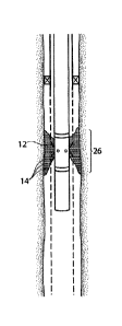
[0033] FIGS. 1-4 show an intervention tool 10 as it may be used to fix a
damaged screen section 16 by locally plugging the screen with a sealant. FIG.
1
is side view of a wellbore with a damaged screen section 16. FIG. 2 shows a
side view of an intervention tool 10 being delivered to the damaged screen
section 16. This figure shows the tool 10 as it conveys the fluid 12 downhole,
with magnetic components 20, 22 on the running tool 10. The tool 10 may be run
in on wireline, slickline, coiled tube, jointed tubing, or any other
appropriate
system to the location of the damage.
[0034] The tool 10 generally has a shaft 11 that can be delivered
downhole.
When the tool 10 has reached the location where the fluid 12 is to be
injected, the
fluid 12 is caused to be pushed out of the tool 10 through injection ports 24.
FIG.
3 shows a side view of fluid 12 being delivered to the damaged screen 16
section
to create a seal. FIG. 4 shows the seal 18 created on the screen section after
removal of the tool 10.
[0035] In one aspect, the fluid 12 delivered is generally a carrier fluid
12
that is a magnetorheological fluid, ferrofluid, or a fluid otherwise having
magnetically responsive particles 14 contained therein. The fluid 12 can
generally be a fluid to which its resistance to flow is modified by subjecting
it to a
magnetic field. The carrier fluid 12 may be formed from magnetically
responsive
particles 14 and a carrier to form a slurry. In one aspect, the fluid 12
contains
magnetically responsive particles 14 of a ferromagnetic material, such as
iron,
nickel, cobalt, any ferromagnetic, diamagnetic or paramagnetic particles,
ferromagnetic particles, any combination thereof, or any other particles that
can
receive and react to a magnetic force. Any particles 14 that are attracted to
CA 02927575 2016-04-14
WO 2015/094274 9/27 PCT/US2013/076505
magnets can be used in the fluid 12 and are considered within the scope of
this
disclosure. (It should be noted that the figures are not drawn to scale and
for
illustrative purposes only. For example, the particles 14 are not easily
visible due
to their small size, and they have thus been exaggerated in the figures for
ease of
viewing.)
[0036] Any suitable particle size can be used for the particles 14 of the
fluid
12. For example, the nanoparticles may range from the nanometer size up to the
micrometer size. In one example, the particles may be in the size range of
about
100 nanometers to about 1000 nanometers. In another example, the particles
may be less than 100 nanometers. In another example, the particles may range
into the micrometer size, for example up to about 100 microns. It should be
understood that other particles sizes are possible and considered within the
scope of this disclosure. In embodiments where the particles are referred to
as
"nanoparticles," it should be understood that the particles may also be of
micron
sizes, or a combination of nanoparticles and microparticles. The particles 14
can
also be any shape, non-limiting examples of which include spheres, spheroids,
tubular, corpuscular, fiber, oblate spheroids, or any other appropriate shape.
Multiple shapes and multiple sizes may be combined in a single group of
particles
14.
[0037] The shape of the actual particles may be altered in an effort to
create better internal locking of the particles. For example, round particles
may
be used. However, elongated or rod-shaped particles may lock more securely
and create a stronger packer in place. The particles can be shaped to better
entangle with one another to form the packer. The length of the particles may
CA 02927575 2016-04-14
WO 2015/094274 10/27 PCT/US2013/076505
also be modified to provide varying locking configurations. It is believed
that a
particularly useful length may be from about 10 nanometers to about 1
millimeter,
although other options are possible and within the scope of this disclosure.
[0038] The fluid 12 may generally be formed from magnetically responsive
particles 14 that are mixed into a carrier fluid. Any suitable carrier fluid
may be
used that can contain the magnetically responsive particles 14, allow a flow
of the
particles 14, and can be used to form a seal 18. In a specific aspect, the
carrier
fluid is a polymer precursor. The polymer precursor may be a material that
forms
cross-links. Non-limiting examples of polymer precursors that may be used in
connection with this disclosure include but are not limited to plastics,
adhesives,
thermoplastics, thermosetting resins, elastomeric materials, polymers,
epoxies,
silicones, sealants, oils, gels, glues, acids, thixotropic fluids, dilatant
fluids, or any
combinations thereof. The polymer precursor may be a single part (for example,
a moisture or UV cure silicone). Alternatively, the polymer precursor may be a
multi-part (for example, a vinyl addition or a platinum catalyst cure
silicone)
system.
[0039] The polymer precursor should generally be a material that can
carry
magnetically responsive particles 14 and cure or otherwise set upon
appropriate
forces, environmental conditions, or time. The polymer precursor should be a
material that can create a seal. The polymer precursor should be a material
that
can be carried downhole on the tool 10 and activated or otherwise mixed
downhole. For example, a material that has a requirement of being mixed at the
surface and pumped downhole, such as cement, is not preferable. Polymer
precursors provide the feature of being deliverable downhole without having to
be
CA 02927575 2016-04-14
WO 2015/094274 11/27 PCT/US2013/076505
activated for immediate use. Any other type of polymer precursor or other
material that may act as a carrier for magnetically responsive particles 14
and
that can cure to form a seal or otherwise act as a sealant is generally
considered
within the scope of this disclosure.
[0040] The carrier fluid 12 can form a seal or otherwise act as a sealant
in
response to appropriate forces, environmental conditions, or time. One non-
limiting example of a suitable carrier fluid includes an epoxy. Other non-
limiting
examples of suitable carriers include one-part or multi-part systems. One
specific
option could be a one-part or a multi-part epoxy. Other non-limiting examples
of
a suitable carrier fluid include silicones, oils, polymers, gels, elastomeric
materials, glues, sealants, water, soap, acids, fusible metals, thixotropic
fluids,
dilatant fluids, any combination thereof, or any other fluid that can contain
the
nanoparticles and allow their flow but create an ultimate seal. Any material
that
may act as a carrier for the particles 14 and that can solidify, cure, or
harden (to
form a seal or otherwise act as a sealant upon appropriate forces,
environmental
conditions, or time) is possible for use and considered within the scope of
this
disclosure.
[0041] In some aspects, the carrier may be formed in multiple steps. For
example, an epoxy may be used that has a two-part set-up (for example, a two-
part epoxy), where parts A and B are housed separately from one another and
mixed as they pass through a static mixer on their way to the damaged area to
be
repaired. In another aspect, the particles 14 may be in one part of fluid and
another part of the carrier fluid may be in a second part, such that the two
(or
more) parts are combined upon dispensing.
CA 02927575 2016-04-14
WO 2015/094274 12/27 PCT/1JS2013/076505
[0042] The tool contains the carrier fluid 12 therein. In one aspect, the
carrier fluid 12 may be housed in a housing with a delivery conduit. The
housing
may house the carrier fluid 12 in a pre-combined condition. Alternatively, the
housing may be designed to maintain parts A and B of carrier fluid 12
separately
until just prior to deployment of the carrier fluid 12. For example, there may
be
provided a divider wall within housing to maintain parts of the polymer
precursor
of the carrier fluid 12 separate from one another until deployment.
[0043] As shown in FIGS. 2 and 3, the tool 10 may have a pair of magnet
rings 20, 22. Magnet rings 20, 22 may encircle the outside diameter of the
tool
shaft 11, they may be positioned on the inner diameter of the tool 10, they
may
be embedded into the tool material, or otherwise. Magnets 20, 22 may be
attached or otherwise secured to the tool 10 via any appropriate method. Non-
limiting examples of appropriate methods include adhesives, welding,
mechanical
attachments, embedding the magnets within the tool material, or any other
option. Additionally or alternatively, magnet components may be pre-installed
on
the completion, as described for further aspects below. The magnets can be
either permanent magnets or electromagnets.
[0044] Although shown and described as rings 20, 22, the magnets may be
magnetic blocks or any other shaped magnetic component that can be spaced
apart on tool 10 and provide the desired functions of attracting the
magnetically
responsive particles 14 of the fluid 12. For example, although two magnet
rings
20, 22 are shown for ease of reference, it should be understood that magnet
rings 20, 22 may be a series of individual magnets positioned in a ring around
the
area to be made magnetic. The general concept is that magnets 20, 22 form a
CA 02927575 2016-04-14
WO 2015/094274 13/27 PCT/US2013/076505
magnetic space therebetween that extends radially from the tool 10. The
magnetic space extends past the outer diameter of the tool.
[0045] The features described may also work on the principle of electro-
rheological fluid, where the fluid responds to electrical fields that are
produced by
a component(s) on the running tool, on the completion, or both.
[0046] The tool may also have one or more fluid injection ports 24. The
one or more injection ports 24 carry the fluid 12 from the interior of the
tool 10 to
the desired target area. In one aspect, the injection ports 24 may be sealed
or
otherwise covered by a component that prevents the carrier fluid 12 from
exiting
the tool 10 until desired. On one aspect, a rupture disc may be provided,
which
ruptures upon application of pressure. The carrier fluid 12 may be deployed
through the tool via any appropriate method, such a pressure from a piston or
any other component or force that can apply pressure to the fluid 12.
[0047] In one aspect, the rupture disc may be a small piece of foil,
metal, or
other material that contains the fluid 12 inside the intervention tool 10
until
pressure is applied. In another aspect, the rupture disc may be a dissolvable
plug that dissolves upon a certain pH environmental, or otherwise ceases to
contain the fluid 12 in response to a pre-selected trigger. For example, the
rupture disc may be formed as a temperature sensitive material or shape memory
material plug that dissolves upon a certain temperature, shrinks or enlarges
at a
certain environmental condition, or otherwise ceases to contain the fluid 12
in
response to a pre-selected trigger. For example, the dissolving of plug could
cause a piston to push the fluid 12 out the created opening.
CA 02927575 2016-04-14
WO 2015/094274 14/27 PCT/US2013/076505
[0048] In additional or alternate aspects, a passive deployment of the
rupture disc can allow the fluid 12 to disperse to the target area. For
example, an
electronically triggered system may be used to activate the release of the
fluid.
The fluid 12 may be pushed out through injection port 24 by a downhole power
unit (DPU), an electronic rupture disc (ERD), hydrostatic pressure, a Ledoux-
style
or moyno-style hydraulic pump, or any other number of means. Any method or
system that delivers fluid from the interior of the tool to the desired
location near
the damaged screen is envisioned with within the scope of this disclosure.
[0049] Once deployed, the carrier fluid 12 passes through a magnetic
field
created by magnets 20, 22. This causes the magnetically responsive particles
14
to align with the magnetic field created. This alignment causes the
magnetically
responsive particles 14 to hold the carrier fluid 12 between magnets 20, 22.
The
interaction between the particles 14 and the magnets 20, 22 allows the carrier
fluid 12 to fill the space 26 between the magnets 20, 22 but prevents the
fluid 12
from moving very far past the desired space 26.
[0050] This allows the fluid 12 to create a remedial screen patch or seal
18
by fixing the damaged section of screen 16 by locally plugging the damaged
screen area with a sealant. The sealant (formed by the carrier fluid 12 and
magnetically responsive particles 14) is pumped out of the tool 10, into the
screen 16. The magnets 20, 22 constrain its axial flow. Once the sealant had
set
and the section of the screen 16 is no longer permeable or otherwise secured
as
desired, then the tool 10 can be removed.
[0051] The tool 10 may have an outer coating that allows an easy release
of the tool from the cured or set sealant. The outer coating may be a Teflon
CA 02927575 2016-04-14
WO 2015/094274 15/27 PCT/US2013/076505
coating, a mold release coating, or any other type of coating that allows
removal
of tool 10 without disrupting the seal 18.
[0052] In another embodiment, the tool 10 may be used to plug water
inflow. One of the problems that can occur during the process of oil recovery
from a formation is loss of the well's productivity at the onset of water
inflow.
Accordingly, it may be necessary to block and/or stop water producing zones.
The tool 10 and its method of use described herein may be used to apply a
sealant over an area 28 that is producing undesired water inflow, as shown by
the solid arrows "W." The desired oil inflow is shown by dotted arrows "0."
FIG.
shows a side view of a wellbore with a water inflow area 28 that needs to be
plugged. FIG. 6 shows a side view of an intervention tool 10 being delivered
to
the area. FIG. 7 shows a side view of carrier fluid 12 being delivered to the
area
28 to be sealed. FIG. 8 shows the sealed area after removal of the tool 10.
This
figure shows the stopped water "W" flow, but the continued oil "0" flow. In
use,
the magnets 20, 22 cause slowing and stoppage of the carrier fluid 12 due to
interaction between magnetically responsive particles 14 and the magnets 20,
22.
Once the seal has 18 been formed, the tool 10 is removed.
[00531 In one aspect, the self-contained remedial system extrudes a
carrier
fluid 12 that comprises either a sealant or a shear stress fluid over the
location 28
of water production. The location of water production is shown by arrows W.
The result is that flow from that water inflow area 28 zone is minimized. No
more
water W may flow into the production tubing. This is evidenced by the dotted
arrows "0" in FIG. 8, which indicate the flow of oil but, not water, into the
production tubing.
CA 02927575 2016-04-14
WO 2015/094274 16/27 PCT/US2013/076505
[0054] In a related aspect, it may be necessary to block an in-flow
device
(ICD and/or an AICD) 30 flow path. As shown in FIGS. 9-12, the intervention
tool
could be used to selectively stop production of a zone with an ICD/AICD 30
control by squeezing a sealant fluid 12 into the ICD/AICD flow path 32. FIG. 9
is
side view of a wellbore with a water in-flow control device 30 that is
malfunctioning and should be blocked. The produced fluid travels through the
screen 34, through an ICD/AICD 30, and into the production tubing 36. FIG. 10
shows a side view of an intervention tool 10 being delivered through the
production tubing 36 and to the in-flow control device area 30. FIG. 11 shows
a
side view of carrier fluid 12 being delivered to the in-flow control device
flow path
32 to be blocked to create a seal 18. FIG. 12 shows the blocked in-flow
control
device 30 with a seal 18, after removal of the tool. This shows that once the
fluid
12 (which may be an epoxy, a polymer precursor, or other sealant substance
with
magnetically responsive particles) is deployed or extruded out of the tool 10,
the
tool 10 may be removed. The result is that the blocked zone would no longer
produce. This would allow an ICD/AICD 30 to be switched off, instead of simply
limiting flow.
[0055] Another aspect could be to provide remedial zonal isolation. The
tool 10 may be run inside of a section of screens. In this aspect, the tool 10
could
be used to isolate different zones within those screens that would otherwise
be in
communication outside of the completion. This is similar to the remedial
screen
path concept described above, but with a different intent. In this instance,
there
is no damage to the screen that is being fixed with the seal. Instead, the
fluid 12
is pumped to isolate the production in the top part of the screen from that of
the
CA 02927575 2016-04-14
WO 2015/094274 17/27 PCT/US2013/076505
bottom part. This can prevent fluid communication in the outer annulus between
these two zones.
[0056] A further aspect provides remedial securement. For example, the
tool 10 could be used to locally secure a section of the completion. For
instance,
it is possible to use the tool 10 for plugging perforations 38 or as a
remedial
securing system. FIG. 13 shows side view of a wellbore with perforations 38 to
be plugged. FIG. 14 shows a side view of an intervention tool 10 being
delivered
to the perforation area. FIG. 15 shows a side view of carrier fluid 12 being
delivered into the perforations 38 to create remedial securement. FIG. 16
shows
the sealed perforations after removal of the tool.
[0057] In any of the aspects described, once the carrier fluid 12 has
been
positioned as desired, the fluid 12 is allowed to cure or harden or otherwise
create a seal. The polymer precursor material of the carrier fluid 12 may
begin to
cross-link and cure. For example, the passage of time, applied heat, and/or
exposure to certain fluids or environments causes the carrier fluid 12 to set
and
/or cure to form a packer 10 in the desired location. For example, a
elastomeric
carrier may cure via vulcanization. A one-part epoxy may cure after a time
being
exposed to the wellbore fluids. A silicone sealant could be used as a one-part
epoxy which sets and cures with exposure to water. A slow setting gel or other
gel may set in the presence of water. Two¨part systems generally cure due to a
chemical reaction between the components to the two parts upon mixing. Other
carriers/sealants may be used that cure based on temperature or any other
environmental cue.
CA 02927575 2016-04-14
WO 2015/094274 18/27 PCT/1JS2013/076505
[0058] Further aspects, alternate options, and possible alterations to
the
above-disclosure are also possible. For example, the carrier fluid 12 may be
selected so that it has self-healing properties that will provide a self-
healing seal.
For example, silicone sealants have been shown to have self-healing
properties.
Carrier fluids that set into a self-healing material may be advantageous for
repairing damage from over-flexing, over-pressurization, tubing movement, and
so forth. Self-healing can further be accomplished by adding an encapsulated
healing agent and catalyst into the mix. Crack formation would rupture the
encapsulated healing agent which would seal the crack. Using hollow glass
fibers may also provide a self-healing packer element.
[0059] Additionally, in the above-described aspects, deployment of the
carrier fluid 12 is accomplished by generally forcing the carrier fluid into
the area
to be sealed. Alternatively, the solution of particles could be encased in a
dissolvable bladder or bag. When the bladder dissolves or degrades, the
particles may be attracted toward the magnets. The particle solution can be
encased in a water-dissolvable case with a material such as polyglycolic acid
(PGA), polylactic acid (PLA), salt, sugar, or other water-dissolvable (or
other
solution-dissolvable, such as acid or brine contact) material. The reactions
could
be triggered by contact with water, acid, or brine solution. Additionally or
alternatively, the carrier fluid 12 can be encased in a temperature-degradable
case with a material such as a fusible metal, a low-melt thermoplastic, or an
aluminum or magnesium case that would galvanically react in the water. Applied
voltages may be used to cause the galvanic reaction to happen nearly
instantaneously and/or voltage could be used to delay the galvanic reaction.
CA 02927575 2016-04-14
WO 2015/094274 19/27 PCT/US2013/076505
[0060] Although some methods and aspects have been described above,
the general steps and methods described for use of the intervention tool 10
may
be used for remedial work anywhere along the wellbore once the completion has
been run.
[0061] Additionally or alternatively, a further aspect provides pre-
placed
magnets on the completion. The pre-placed magnet feature may be used with
the intervention tool 10 as shown and described above, which has magnets 20,
22 positioned thereon. Additionally or alternatively, pre-placed magnets on
the
completion may be used with a delivery/service tool that can deliver the fluid
12
but that does not have magnets positioned thereon. For example, in one aspect,
one or more magnets may be installed on pre-determined locations of the
completion before the completion is run into the well. As an example, if zonal
isolation is required between two sections of screen, magnetic barriers could
be
pre-installed between the sections of screen. One or more injection ports
could
be installed between the magnets. This provides the possibly for creating a
seal
through the screens if that becomes necessary. For example, the magnetic field
can be created with one or more magnets incorporated into the screens during
assembly. Additionally or alternatively, if an intervention tool with magnets
is
used, the magnetic field could permeate through the screens from the inner
diameter of the tool 10.
[0062] As another example, magnets 40, 42 may be pre-positioned on
either side of an ICD/AICD 30. FIG. 17 shows a side view of a completion with
an ICD/AICD 30 having magnets pre-placed alongside. This would allow the
later option of delivering a carrier fluid 12 to that area in order to block
the
CA 02927575 2016-04-14
WO 2015/094274 20/27 PCT/US2013/076505
ICD/AICD 30 if needed. Formation fluid "F" is shown flowing through the
formation wall 44, into the ICD or AICD 30, and into an opening 46 in the
production tubing 36. If the carrier fluid 12 is delivered into the opening
46, it
would effectively block the function of the ICD/AICD 30. In this example, the
carrier fluid 12 may be drawn into the ICD/AICD 30. By providing magnets 40,
42
on the completion 36 instead of on the running tool 10 (as previously
described),
traditional packer elements may be relied on to constrain the fluid motion
between the tool 10 and the completion 36. The magnets 40, 42 may provide the
axial flow constraint external to the completion.
[0063] In an further aspect, magnets 40, 42 may be positioned on the
completion, as well as on an intervention tool 10. This option is illustrated
by
FIG. 18. FIG. 18 shows a side view of FIG. 17 with an intervention tool 10
having
magnets 20, 22 positioned thereon in use. This figure illustrates an
intervention
tool 10 that is configured to inject fluid 12 into a desired space 48 (e.g.,
between
the tool 10 and the completion). Magnets 20, 22 on the tool 10 can constrain
the
carrier fluid 12 to form a seal in the desired space 48. In this example, the
carrier
fluid 12 would form a seal in the space 48 between magnets 20, 22 on the tool
10
in order to block the opening 46 in the completion.
[0064] The aspects described herein may be used to block or seal other
parts of the completion. For example, FIG. 19 shows a side view of a shunt
tube
50 having magnets 52, 54 pre-placed adjacent thereto. The shunt tube 50 is
shown positioned generally parallel to the completion string 56 with a packer
element 58 in place. A gravel pack 60 is also in place. The shunt tube 50 is
generally used as an underpass below the packer 58. It is desirable to have
the
CA 02927575 2016-04-14
WO 2015/094274 21/27 PCT/US2013/076505
shunt tube 50 open and flowing for the gravel pack process, but it may be
desirable to plug the shunt tube 50 once the gravel pack 60 has been placed.
In
this case, magnets 52, 54 positioned directly on the shunt tube 50 may slow
carrier fluid 12 that can be delivered along with (or through) the gravel
pack. This
carrier fluid 12 may be referred to as gravel-laden fluid in this instance.
The
gravel-laden carrier fluid 12 is allowed to pass through the shunt tube 50,
but
caused to stop due to magnetic forces between the magnetically responsive
particles in the fluid 12 and the magnets 52, 54 on the shunt tube 50. This
would
effectively block the shunt tube 50 from conveying further fluids.
[0065] The aspects described herein may also be used to deliver any type
of working fluid downhole. For example, the tool 10 may be used to deliver
magnetorheological acids that could be used to dissolve plugs, to provide
pinpoint well stimulation, to clean perforations, or any other uses. This
disclosure
is not intended to limit the alternative fluids that may be delivered in any
way. For
example, in one variation, a first fluid could be injected into an AICD/ICD to
shut-
off flow through the device. This first fluid may be used to create complete
water
blockage. After time, a second fluid can be injected into the AICD/ICD to
remove
the first fluid. This would return flow through the screen section.
Alternatively,
the second fluid could be used to dissolve a bypass around the AICD/ICD and
return flow through the screen section.
[0066] The remedial process described generally use magnets to constrain
the fluid and to direct the fluids toward the area that needs sealing or
desired
treatment. This disclosure also allows a user to create a pinpoint placement
of
fluid in an already-existing wellbore. The magnets are used to constrain the
fluid
CA 02927575 2016-04-14
WO 2015/094274 22/27 PCT/1JS2013/076505
and to direct the fluid to its target location. This approach includes adding
magnetically responsive or ferromagnetic particles to a carrier fluid so that
the
resulting magnetorheological fluid interacts with the magnets on a service
tool or
elsewhere. The result is a targeted stimulation, a targeted acid job, or a
targeted
placement of chemical such as a scale inhibiter or any other working fluid to
be
delivered downhole.
[0067] In one aspect, there is provided an intervention tool for use
downhole in a wellbore, comprising a tool shaft; at least two magnets
positioned
with respect to the tool shaft; a carrier fluid comprising a polymer precursor
and
magnetically responsive particles; one or more injection ports on the tool
shaft; a
fluid deployment system to cause deployment of the carrier fluid out of the
tool
shaft through the one or more injection ports.
[0068] In a further aspect, there is provided a method for constraining a
sealant to create a remedial repair patch in a downhole well, comprising:
providing a radially extending magnetic force field; providing a
magnetorheological carrier fluid with a polymer precursor component that cures
to form a sealant; dispensing the magnetorheological fluid such that the fluid
is
constrained by the magnetic force field, allowing the fluid to cure to form to
form a
remedial repair patch.
[0069] The foregoing description, including illustrated aspects and
examples, has been presented only for the purpose of illustration and
description
and is not intended to be exhaustive or to limiting to the precise forms
disclosed.
Numerous modifications, adaptations, and uses thereof will be apparent to
those
skilled in the art without departing from the scope of this disclosure.