Note: Descriptions are shown in the official language in which they were submitted.
DESCRIPTION
METHODS, SYSTEMS AND DEVICES FOR PRE-OPERATIVELY
PLANNED GLENOID PLACEMENT GUIDES AND USES THEREOF
10 TECHNICAL FIELD
The presently disclosed subject matter relates to methods, systems
and devices for pre-operatively planned glenoid placement guides. The
presently disclosed subject matter also relates to the use of such glenoid
placement guides in patients undergoing shoulder surgery.
BACKGROUND
Shoulder replacement is a common surgical operation that has
achieved positive results for many patients. Indeed, approximately 10% of
joint replacement procedures globally are related to the shoulder. Many
shoulder procedures are performed in a patient where substantially normally
bone exists for orientation and fixation of a prosthetic replacement, or
resurfacing. In these cases, the need for the shoulder replacement can
often times be related mostly to the arthritic condition of the joint, and
relative
absence of healthy cartilage.
In some patients, however, one or more of the bones of the shoulder
are not only arthritic, but have also had previous conditions that have caused
bone to wear away. In such cases, there may not be sufficient bone to
adequately affix a prosthetic implant to the bone, or the bones may have
been worn such that the orientation of a joint replacement cannot be
satisfactorily determined to ensure a positive patient outcome.
There are a number of factors that complicate the selection,
orientation and affixation of prosthetic implant devices, such as glenoid
- 1 -
Date Recue/Date Received 2020-04-14
CA 02927811 2016-04-15
WO 2015/056097 PCT/IB2014/002759
implants and/or humeral implants. Failure to properly account for each
factor can lead to improperly sized, misaligned and/or poorly affixed implants
that result in a poor surgical outcome for the patient.
In order to increase the likelihood of successful patient outcomes in
patients undergoing shoulder surgery, methods, systems and devices are
needed that allow for the full understanding and incorporation of all
necessary factors for optimization of shoulder implant selection and
placement. Thus, a need remains for methods, systems and devices for pre-
operatively planned shoulder surgery guides and implants that achieve
desired outcomes.
SUMMARY
The presently disclosed subject matter provides methods, systems
and devices for pre-operatively planned glenoid placement guides. The
presently disclosed subject matter also provides methods of using glenoid
placement guides in patients undergoing shoulder surgery.
An object of the presently disclosed subject matter having been stated
hereinabove, and which is achieved in whole or in part by the presently
disclosed subject matter, other objects will become evident as the
description proceeds when taken in connection with the accompanying
Examples as best described hereinbelow.
BRIEF DESCRIPTION OF THE DRAWINGS
The presently disclosed subject matter can be better understood by
referring to the following figures. The components in the figures are not
necessarily to scale, emphasis instead being placed upon illustrating the
principles of the presently disclosed subject matter (often schematically). In
the figures, like reference numerals designate corresponding parts
throughout the different views. A further understanding of the presently
disclosed subject matter can be obtained by reference to an embodiment set
forth in the illustrations of the accompanying drawings. Although the
illustrated embodiment is merely exemplary of systems for carrying out the
presently disclosed subject matter, both the organization and method of
- 2 -
CA 02927811 2016-04-15
WO 2015/056097 PCT/IB2014/002759
operation of the presently disclosed subject matter, in general, together with
further objectives and advantages thereof, may be more easily understood
by reference to the drawings and the following description. The drawings
are not intended to limit the scope of this presently disclosed subject
matter,
which is set forth with particularity in the claims as appended or as
subsequently amended, but merely to clarify and exemplify the presently
disclosed subject matter.
For a more complete understanding of the presently disclosed subject
matter, reference is now made to the following drawings in which:
Figure 1A is a schematic illustration of a step in a pre-operative
planning method for designing a shoulder surgery guide where the anterior
edge of a glenoid implant is aligned with an anterior edge of a glenoid bone,
according to an embodiment of the disclosed subject matter;
Figure 1B is a schematic illustration of a step in a pre-operative
planning method for designing a shoulder surgery guide where the
retroversion of a glenoid implant is adjusted, according to an embodiment of
the disclosed subject matter;
Figure 1C is a schematic illustration of a step in a pre-operative
planning method for designing a shoulder surgery guide where the
augmentation of a glenoid implant is adjusted, according to an embodiment
of the disclosed subject matter;
Figure 1D is a schematic illustration of a step in a pre-operative
planning method for designing a shoulder surgery guide where the inferior tilt
of a glenoid implant is adjusted, according to an embodiment of the
disclosed subject matter;
Figure 1E is a schematic illustration of a step in a pre-operative
planning method for designing a shoulder surgery guide where bone support
for a glenoid implant is evaluated, according to an embodiment of the
disclosed subject matter;
Figure 1F is a schematic illustration of a step in a pre-operative
planning method for designing a shoulder surgery guide where the
medialization of a glenoid implant is adjusted by assessing the volumetric
- 3 -
CA 02927811 2016-04-15
WO 2015/056097 PCT/IB2014/002759
amount of bone needed to be removed by reaming, according to an
embodiment of the disclosed subject matter;
Figure 1G is a schematic illustration of a step in a pre-operative
planning method for designing a shoulder surgery guide where fixation
support in the absence of central pegs that penetrate a vault medially is
analyzed, according to an embodiment of the disclosed subject matter;
Figure 1H is a schematic illustration of a step in a pre-operative
planning method for designing a shoulder surgery guide where a joint line is
analyzed by comparing an original joint line and a new joint line, according
to
an embodiment of the disclosed subject matter;
Figure 11 is a schematic illustration of a step in a pre-operative
planning method for designing a shoulder surgery guide where widths of the
glenoid implant and the glenoid bone are measured and matched after
reaming and aligning inferior and superior axes of the glenoid implant and
bone, according to an embodiment of the disclosed subject matter;
Figure 2A is a schematic illustration of a step in a pre-operative
planning method for designing a shoulder surgery guide where the diameter
of a humeral head is determined, according to an embodiment of the
disclosed subject matter;
Figure 2B is a schematic illustration of a step in a pre-operative
planning method for designing a shoulder surgery guide where the height of
a humeral head is determined, according to an embodiment of the disclosed
subject matter;
Figure 2C is a schematic illustration of a step in a pre-operative
planning method for designing a shoulder surgery guide where the size of a
humeral bone implant from Houndsfield units measured by computed
tomography scan is determined, according to an embodiment of the
disclosed subject matter;
Figure 2D is a schematic illustration of a step in a pre-operative
planning method for designing a shoulder surgery guide where a best fit size
of implant from a range of sizes is determined, according to an embodiment
of the disclosed subject matter;
- 4 -
CA 02927811 2016-04-15
WO 2015/056097 PCT/IB2014/002759
Figure 3 is a schematic illustration of a step in a pre-operative
planning method for designing a shoulder surgery guide where vectors are
compared in three dimensions to measure the distance of relocation of
humeral tuberosity compared to the scapula, according to an embodiment of
the disclosed subject matter;
Figure 4 is a schematic illustration of a step in a pre-operative
planning method for designing a shoulder surgery guide where range of
motion analysis is conducted, including virtually positioning implants through
extreme ranges of motion to measure impact locations and compensate for
necessary functional range of motion, according to an embodiment of the
disclosed subject matter;
Figure 5 is a schematic illustration of a step in a pre-operative
planning method for designing a shoulder surgery guide where soft tissue
analysis comprising determining key soft tissue insertion points is conducted,
according to an embodiment of the disclosed subject matter;
Figure 6 is a schematic illustration of a step in a pre-operative
planning method for designing a shoulder surgery guide where penetration
of the cortical wall anteriorily of the vault is assessed, according to an
embodiment of the disclosed subject matter;
Figure 7 is a schematic illustration of a step in a pre-operative
planning method for designing a shoulder surgery guide where the width of
the greater tuberosity to medial head edge with an implant is compared to
the anatomic width, according to an embodiment of the disclosed subject
matter;
Figures 8A and 8B are perspective front and rear views, respectively,
of a glenoid guide, according to an embodiment of the disclosed subject
matter;
Figure 9 is a perspective view of a glenoid guide fitted to a glenoid on
a scapula bone, according to an embodiment of the disclosed subject matter;
Figure 10 is a perspective view of a glenoid guide fitted to a glenoid
on a scapula bone with a drill, according to an embodiment of the disclosed
subject matter;
- 5 -
CA 02927811 2016-04-15
WO 2015/056097 PCT/IB2014/002759
Figure 11 is a side view of a depth-control pin, according to an
embodiment of the disclosed subject matter;
Figure 12A and 12B are perspective views of a glenoid guide fitted to
a glenoid on a scapula bone prior to (Figure 12A) and after (Figure 12B) a
depth-control pin is inserted, according to an embodiment of the disclosed
subject matter; and
Figures 13A and 13B are perspective views of a depth-control pin
affixed to a glenoid on a scapula bone prior to receiving (Figure 13A) and
after receiving (Figure 13B) a reamer device, according to an embodiment of
the disclosed subject matter.
DETAILED DESCRIPTION
Patients requiring shoulder surgery may have one or more of the
bones of the shoulder that are not only arthritic, but may also have had
previous conditions that have caused bone to wear away. In such cases,
there may not be sufficient bone to adequately affix a prosthetic implant to
the bone during a routine shoulder surgery. Indeed, the bones may have
been worn such that the orientation of a joint replacement cannot be
satisfactorily determined to ensure a positive patient outcome.
The glenoid bone can be subject to increased wear due to bone
arthritic conditions of the joint, and due to alterations of a normal soft
tissue
envelope surrounding the joint. In such cases, the orientation of the face of
the glenoid portion of the scapula bone may be altered so that the humeral
bone is no longer appropriately apposed to the glenoid surface. In the case
where the glenoid is severely worn, there can be two or more risks a
surgeon must balance in an attempt to improve shoulder function and pain
relief.
First, if the optimal orientation of the diseased but treated shoulder is
not found and replicated with the prosthesis the patient may experience most
operative complications related to subluxation or dislocation of the replaced
shoulder joint. This can occur either due to passive inputs to the shoulder
- 6 -
CA 02927811 2016-04-15
WO 2015/056097 PCT/IB2014/002759
(e.g., leaning against it, or lying in bed), or due to active firing of
surrounding
soft tissue which is not able to be constrained by the replaced joint
surfaces.
Additionally, the fixation of a replacement prosthesis, or implant, to
the native patient bone can be problematic. Frequently,
in order to
counteract the risks associated with joint subluxation and dislocation
described above, it can be necessary for a surgeon to orient or position the
replacement prosthesis or implant in a position better suited to resist
imbalanced muscle forces. In such cases, separation forces between the
implant and the bone can increase, which in turn can increase the potential
for loosening of the joint prosthesis in the bone. Implant loosening can be
related to accelerated implant wear, bone erosion, increased tissue
inflammation, joint synovitis, and pain.
In patients that have undergone shoulder replacement surgery, range
of motion and strength are dependent on shoulder kinematics, which are in
turn dependent on a host of factors. Such factor can, for example, include
for example implant size, implant position, the design of implant shape, the
joint line and soft tissue tension. In some cases it can be difficult to
predict
optimal implant size and position/orientation using currently available guides
and implants. Often times a surgeon finds that there are too many variables
to manage at one time. Moreover, the size choices of implants can be
limited to the lowest practically functional groups to reduce economic burden
to the health care system. Current implant designs and methodologies are
inadequate to address these challenges because they are of significant cost,
require time to develop, include increased risk of implant failure, and rely
on
human judgment of potential outcomes post-operatively.
There are many factors that can affect the optimal positioning of
shoulder implants during replacement surgery. For example, such factors
can include the patient size, relative bone wear, soft tissue strength and
condition, six degrees-of-freedom positioning of the glenoid and/or the
humeral prosthesis, selected implant size, preoperative patient activity and
strength levels, post operative treatment protocols, size and density of
patient bone. Additional factors can include patient smoking status,
concomitant handicaps and/or patient problems. It can be quite difficult for a
- 7 -
CA 02927811 2016-04-15
WO 2015/056097 PCT/IB2014/002759
surgeon to understand and balance these factors simultaneously. In
addition, only a few of these factors are able to be controlled by the
surgeon.
Finally, each factor does not necessarily have an equally weighted impact on
patient outcome. Nevertheless, it is considered that the implant size,
position, orientation and bone preparation of the glenoid and the humerus
can have a significant impact on the surgical outcomes.
A factor that further complicates, or makes more difficult, a surgeons
task of optimally placing a replacement component or implant to counteract
these risk is the fact that the condition of the scapula is such that few
landmarks exists for the surgeon the comprehend the implant position within
the bone. Thus, frequently a surgeon might find that the implant position is
not replicating as was envisioned during the surgical intervention.
Others have attempted to improve a surgeon's chance of providing
successful patient outcomes by providing operative techniques and tools.
What is missing, however, is the ability to fully understand and incorporate
multiple factors to optimize the implant selection and placement.
Specifically, in some embodiments, the success of the surgery can be highly
dependent on both the selection of the matching prosthesis or prostheses
(humeral and/or glenoid), as well as positioning of this prosthesis, as well
as
the soft tissue status before the surgery. There have been no previous
attempts at including these factors in surgical planning and implant design.
Disclosed herein are methods, systems and devices for pre-
operatively planned shoulder surgery guides, including glenoid placement
guides, and implants. Methods, systems and devices are provided for the
replacement of the shoulder joint, such as the glenohumeral joint, wherein
the conditions of the humeral and soft tissue envelop is taken into
consideration. More specifically, what is considered is that the shape and
position of the glenoid implant is not based solely on what can be seen and
measured on the scapula, but can be chosen, designed, planned and placed
with incorporation of the same information related to the humerus. After all,
the shoulder is a two part joint, i.e. glenoid and humeral head, wherein both
parts work in conjunction with one another, and the factors that affect
- 8 -
CA 02927811 2016-04-15
WO 2015/056097 PCT/IB2014/002759
performance of the device can in some embodiments include factors from
both sides of the joint.
Appropriate sizing of the prosthesis can be important to successful
outcomes, knowing that oversized or "overstuffed" replacement shoulders
are more likely to dislocate, loosen, be painful, and/or have decreased range
of motion. Replaced joints where the orientation of the prostheses is
improper increases the likelihood of implant dislocation and loosening.
Additionally, over-reaming, or too much bone removal, either on the glenoid,
or the humerus, can be the cause of implant loosening, "under-stuffing" or
inappropriate articular surface placement which can increase pain and
decrease range of motion.
Provided herein in some embodiments is a glenoid implant designed
and manufactured to specifically match the patient anatomy, including
optimal humeral and/or glenoid implant size and shape, and taking into
account one or more of the following factors: assessment of the humeral
implant fit to the humeral bone; relative hardness of the patient bone
preoperatively; height and diameter of the humeral head placed on the
humeral stem; orientation, or "offset" of the humeral head; and optimal bone
removal for preservation of soft tissue insertion and attachment.
Also provided herein are methods, systems and devices for creation
of a shoulder surgery guide, including glenoid placement guides, based on
pre-operative planning which takes into consideration a plurality of factors
and assessments. In some embodiments, the creation of a shoulder surgery
guide based on pre-operative planning can comprise one or more of the
following steps, the combination and order of which can vary: aligning an
anterior edge of a glenoid implant with an anterior edge of a glenoid bone;
adjusting a retroversion of the glenoid implant; adjusting an augmentation of
the glenoid implant; adjusting an inferior tilt of the glenoid implant;
evaluating
bone support for the glenoid implant, wherein an amount of a rear surface of
the glenoid implant that is supported by or touching bone is assessed;
adjusting the medialization of the glenoid implant by assessing the
volumetric amount of bone needed to be removed by reaming, or the
minimum total distance of reaming necessary, in order to optimize the bone
- 9 -
CA 02927811 2016-04-15
WO 2015/056097 PCT/IB2014/002759
to implant interface; analyzing the fixation support in the absence of central
pegs that penetrate a vault medially; analyzing the joint line, comprising
comparing an original joint line and a new joint line, wherein the new joint
line is substantially similar to the original joint line; measuring and
matching
widths of the glenoid implant and the glenoid bone after reaming and
aligning inferior/superior axes of the glenoid implant and bone; assessing
and adjusting as needed a thickness/height of the glenoid implant; assessing
and adjusting as needed a depth of a glenoid fossa; assessing and
adjusting as needed a thickness of a graft; determining a diameter of a
humeral head; determining a height of the humeral head; determining a size
of humeral bone implant from Houndsfield units measured by an imaging
technique (e.g. computed tomography (CT) scan); and/or determining a best
fit size of implant from a range of sizes, wherein the range of sizes is
selected from the group consisting of length of stem, size of humeral stem,
diameter of stem, size diameter of head, height of head, and offset of the
center spherical head compared to the center of the face of the humeral
stem.
In some embodiments, a pre-operative planning method for designing
a shoulder surgery guide is provided for designing a guide for the glenoid,
including a glenoid placement guide. Such a method can be separate from
a pre-operative planning method for the humerus, or can in some
embodiments be done in conjunction with the planning for the humerus, or
humeral side of the joint. Such planning steps particular to the glenoid side
of the joint can comprise analysis steps such as those depicted in Figures
1A-11.
For example, a pre-operative planning method for the glenoid can
comprise a step 101, as depicted in Figure 1A, where the anterior edge 18 of
glenoid implant 20 can be aligned 30 with anterior edge 16 of glenoid 12 of
scapula bone 10 of a patient to be treated. In some embodiments, this step,
as with other pre-operative analyses disclosed herein, can be accomplished
virtually based on images, e.g. CT images or X-ray images, taken from a
subject or patient prior to surgery. By aligning anterior edge 18 of glenoid
implant 20 with anterior edge 16 of glenoid 12, data and information can be
- 10 -
CA 02927811 2016-04-15
WO 2015/056097 PCT/IB2014/002759
collected that informs the selection of a glenoid implant and/or supports the
creation of a shoulder surgery guide device specific to the patient or subject
to be treated.
In some embodiments, a pre-operative planning method for the
glenoid can comprise a step 102, as depicted in Figure 1B, where the
retroversion 32 of glenoid implant 20 is adjusted and/or measured. The
retroversion is the placement or degree of posterior rotation of glenoid
implant 20 when glenoid 12, including posterior wear 14 (see Figure 1A), is
reamed or otherwise resurfaced to accommodate glenoid implant 20. Such
a measurement of retroversion 32 of glenoid implant 20 can be in
comparison to the retroversion of the native glenoid in a subject to be
treated. In some embodiments, adjusting the retroversion comprises
adjusting the retroversion to be about 5 degrees (50) to about 10 degrees
(100), with a maximum of 100. In some embodiments, this analysis can be
accomplished virtually based on images taken from a subject or patient prior
to surgery. By measuring and/or adjusting the retroversion 32 of glenoid
implant 20, data and information can be collected that informs the selection
of a glenoid implant and/or supports the creation of a shoulder surgery guide
device specific to the patient or subject to be treated.
In some embodiments, a pre-operative planning method for the
glenoid can comprise a step 103, as depicted in Figure 1C, where a
determination can be made as to the necessity of augmentation 34 to
support glenoid implant 20. In some embodiments, particularly where
glenoid 12 includes posterior wear 14 (or wear at other locations of glenoid
12 not depicted in Figure 1C), augmentation can be necessary and/or
desirable to provide adequate support for the placement and/or attachment
of implant 20. Such a step or analysis can in some embodiments comprise
adjusting, sizing and/or measuring augmentation 34 needed. In some
embodiments, this analysis can be accomplished virtually based on images
taken from a subject or patient prior to surgery. By assessing the need for
augmentation 34, and/or determining the type and/or size of augmentation
34, data and information can be collected that informs the selection of a
-11-
CA 02927811 2016-04-15
WO 2015/056097 PCT/IB2014/002759
glenoid implant and/or supports the creation of a shoulder surgery guide
device specific to the patient or subject to be treated.
In some embodiments, a pre-operative planning method for the
glenoid can comprise a step 104, as depicted in Figure 1D, where the
inferior tilt 36 of glenoid implant 20 can be measured and/or assessed. Such
a measurement of inferior tilt 36 of glenoid implant 20 can be in comparison
to the tilt of the native glenoid in a subject to be treated. In some
embodiments, this analysis can be accomplished virtually based on images
taken from a subject or patient prior to surgery. By assessing the inferior
tilt
36 of glenoid implant 20, data and information can be collected that informs
the selection of a glenoid implant and/or supports the creation of a shoulder
surgery guide device specific to the patient or subject to be treated.
In some embodiments, a pre-operative planning method for the
glenoid can comprise a step 105, as depicted in Figure 1E, where the bone
support 38 for glenoid implant 20 can be measured and/or assessed. Such
an assessment can in some embodiments comprise characterizing and/or
quantifying the amount or degree of bone support 38 for back side 22 of
implant 20, taking into consideration posterior wear 14 (see, e.g., Figures 1A
or 1C; or wear at other locations of glenoid 12 not depicted). In some
embodiments, this analysis can be accomplished virtually based on images
taken from a subject or patient prior to surgery. By assessing the bone
support 38, data and information can be collected that informs the selection
of a glenoid implant and/or supports the creation of a shoulder surgery guide
device specific to the patient or subject to be treated.
In some embodiments, a pre-operative planning method for the
glenoid can comprise a step 106, as depicted in Figure 1F, where
medialization 42 of glenoid implant 20 can be adjusted and/or characterized
by assessing the volumetric amount 40 of bone needed to be removed by
reaming. In some embodiments, this analysis can be accomplished virtually
based on images taken from a subject or patient prior to surgery. By
assessing the bone support 38, data and information can be collected that
informs the selection of a glenoid implant and/or supports the creation of a
shoulder surgery guide device specific to the patient or subject to be
treated.
- 12-
CA 02927811 2016-04-15
WO 2015/056097 PCT/IB2014/002759
In some embodiments, a pre-operative planning method for the
glenoid can comprise a step 107, as depicted in Figure 1G, where fixation
support in the absence of a central peg 44 that penetrates a vault medially of
scapula 10 can be analyzed. In some embodiments, it is desirable to identify
a location on the glenoid for attachment of a prosthesis using a peg or other
fixation component without penetrating the anterior wall of the scapula. In
some embodiments, this analysis can be accomplished virtually based on
images taken from a subject or patient prior to surgery. By assessing the
fixation support, data and information can be collected that informs the
selection of a glenoid implant and/or supports the creation of a shoulder
surgery guide device specific to the patient or subject to be treated.
In some embodiments, a pre-operative planning method for the
glenoid can comprise a step 108, as depicted in Figure 1H, where a joint line
can be analyzed by comparing an original joint line 46 with a new joint line
48 as created when implant 20 is affixed to the glenoid surface of scapula
10. The degree to which the joint line changes or shifts, and/or the change
in the angle, can be used in optimizing the implant 20 selection and/or
placement. In some embodiments, analyzing the joint line, including
comparing the original joint line and the new joint line, can comprise
analyzing the humeral head lateralization. Humeral head lateralization can
comprise the distance the humeral shaft is moved laterally relative to the
scapula after the implants are placed. In some embodiments, this analysis
can be accomplished virtually based on images taken from a subject or
patient prior to surgery. By assessing the joint line, data and information
can
be collected that informs the selection of a glenoid implant and/or supports
the creation of a shoulder surgery guide device specific to the patient or
subject to be treated.
In some embodiments, a pre-operative planning method for the
glenoid can comprise a step 109, as depicted in Figure 11, where the widths
of the glenoid implant 50a and the glenoid bone 50b can be measured and
matched after reaming and aligning inferior 56 and superior 58 axes of the
glenoid implant and bone. Particularly, in some embodiments, a glenoid
implant 50a height 52a and width 54a can be measured and aligned with a
- 13 -
CA 02927811 2016-04-15
WO 2015/056097 PCT/IB2014/002759
glenoid bone 50b height 52b and width 54b along inferior 56 and superior 58
axes. In some embodiments, this analysis can be accomplished virtually
based on images taken from a subject or patient prior to surgery. By
measuring the widths of the glenoid implant 50a and the glenoid bone 50b,
and aligning inferior 56 and superior 58 axes of the glenoid implant and
bone, data and information can be collected that informs the selection of a
glenoid implant and/or supports the creation of a shoulder surgery guide
device specific to the patient or subject to be treated.
Such planning steps particular to the glenoid side of the joint can
comprise analysis steps such as those depicted in Figures 1A-1I, and can
comprise all or some of the steps depicted in Figures 1A-1I, and in some
aspects can be done in any order desired.
Alternatively, in some
embodiments analysis steps particular to fixation elements can be performed
first followed by analysis steps particular to joint articulation.
In some embodiments, a pre-operative planning method for designing
a shoulder surgery guide is provided for designing a guide for the humerus,
or humeral bone. Such a method can be separate from a pre-operative
planning method for the glenoid (discussed above and depicted in Figures
la-l1), or can in some embodiments be done in conjunction with the
planning for the glenoid, or glenoid side of the joint. Such planning steps
particular to the humerus side of the joint can comprise analysis steps such
as those depicted in Figures 2A-2D.
For example, a pre-operative planning method for the humerus can
comprise a step 201, as depicted in Figure 2A, where the diameter d of
humeral head 60 of humerus 62 can be measured. In some embodiments,
this analysis can be accomplished virtually based on images taken from a
subject or patient prior to surgery. By measuring diameter d of humeral head
60, data and information can be collected that informs the selection of a
humeral head implant and/or supports the creation of a shoulder surgery
guide device specific to the patient or subject to be treated.
In some embodiments, a pre-operative planning method for the
humerus can comprise a step 202, as depicted in Figure 2B, where the
height h of humeral head 60 of humerus 62 can be measured. In some
- 14 -
CA 02927811 2016-04-15
WO 2015/056097 PCT/IB2014/002759
embodiments, this analysis can be accomplished virtually based on images
taken from a subject or patient prior to surgery. By measuring height h of
humeral head 60, data and information can be collected that informs the
selection of a humeral head implant and/or supports the creation of a
shoulder surgery guide device specific to the patient or subject to be
treated.
In some embodiments, a pre-operative planning method for the
humerus can comprise a step 203, as depicted in Figure 2C, where the size
of a humeral bone implant stem portion 70 can be determined from
Houndsfield units (the Hounsfield scale, named after Sir Godfrey Newbold
Hounsfield, is a quantitative scale for describing radiodensity) measured by
CT scan. In some embodiments, this analysis can be accomplished virtually
based on images taken from a subject or patient prior to surgery. By
measuring the size of a humeral bone implant, data and information can be
collected that informs the selection of a humeral head implant and/or
supports the creation of a shoulder surgery guide device specific to the
patient or subject to be treated.
In some embodiments, a pre-operative planning method for the
humerus can comprise a step 204, as depicted in Figure 2D, where a best fit
size of humeral implant 72 (the humeral implant includes the humeral head
72 and the humeral stem 70) from a range of sizes can be determined. In
some embodiments, the range of sizes can be selected from the group
consisting of length of stem, size of humeral stem, diameter of stem, size
diameter of head, height of head, and offset of the center spherical
head compared to the center of the face of the humeral stem. In some
embodiments, this analysis can be accomplished virtually based on images
taken from a subject or patient prior to surgery. By determining the most
appropriate size of humeral implant 72, data and information can be
collected that informs the selection of a humeral head implant and/or
supports the creation of a shoulder surgery guide device specific to the
patient or subject to be treated.
Such planning steps particular to the humeral side of the joint can
comprise analysis steps such as those depicted in Figures 2A-2D, and can
comprise all or some of the steps depicted in Figures 2A-2D, and in some
-15-
CA 02927811 2016-04-15
WO 2015/056097 PCT/IB2014/002759
aspects can be done in any order desired.
Alternatively, in some
embodiments analysis steps particular to joint articulation can be performed
first followed by analysis steps particular to fixation elements.
In some embodiments, a pre-operative planning method for designing
a shoulder surgery guide can comprise comparing vectors 80 in three
dimensions to measure the distance of relocation of humeral tuberosity 72
compared to the scapula 10, as depicted in analysis 205 in Figure 3. For
example, there are 3 rotator cuff tendons that attach to the proximal humerus
in the area of the greater tuberosity and the scapula. Such attachment
points are depicted as v and w, respectively, in Figure 3. These tendons
control much of the rotation of the humerus about the scapula as well as
having a part in elevating the humerus. If the vector resolved from these 3
tendons changes, kinematics and kinetics of the glenohumeral joint (joint
comprising the glenoid and humerus) change. For example, changing the
direction of vector 80 can change wear patterns and range of motion (ROM)
of the implanted device versus the native joint. Additionally, in some
embodiments, changing the magnitude of vector 80 by lengthening or
increasing it with a joint prosthesis that is too large for the joint can
result in
decreased ROM, pain, and increased wear of the prosthetic components.
Finally, changing the magnitude of vector 80 by decreasing or shortening it
with a joint prosthesis that is too small for the joint can result in an
unstable
joint that may dislocate and can result in suboptimal mechanics for elevating
the humerus. In some embodiments, this analysis can be accomplished
virtually based on images taken from a subject or patient prior to surgery. By
comparing vector 80 in three dimensions to measure the distance of
relocation of humeral tuberosity 72 compared to the scapula 10, data and
information can be collected that informs the selection of a humeral head
implant, glenoid implant, and/or supports the creation of a shoulder surgery
guide device specific to the patient or subject to be treated.
In some embodiments, a pre-operative planning method designing a
shoulder surgery guide can comprise a step 206, as depicted in Figure 4,
where range of motion (ROM) analysis 82 can be conducted, including
virtually positioning implants 20, 72 through extreme ranges of motion to
- 16 -
CA 02927811 2016-04-15
WO 2015/056097 PCT/IB2014/002759
measure impact locations and compensate for necessary functional ROM.
In some embodiments, this analysis can be accomplished virtually based on
images taken from a subject or patient prior to surgery. By measuring the
ROM with respect to glenoid implants 20 and/or humeral implants 72, data
and information can be collected that informs the selection of glenoid
implant, a humeral head implant and/or supports the creation of a shoulder
surgery guide device specific to the patient or subject to be treated.
In some embodiments, a pre-operative planning method designing a
shoulder surgery guide can comprise a step 207, as depicted in Figure 5,
where soft tissue, e.g. muscle, analysis is conducted. In some aspects, soft
tissue analysis can comprise determining and/or assessing soft tissue
insertion points (e.g., X, Y and Z) and analyzing impacts on and/or impacts
from use of one or more implants (glenoid and/or humeral). In some
embodiments, four rotator cuff muscles and their attachments points can be
analyzed. For example, in some aspects analysis can comprise the
subscapularis that attaches at an attachment point Y near the lesser
tuberosity and at an attachment point X near the anterior glenoid. In some
aspects analysis can comprise the supraspinatus that attaches at an
attachment point Z near the anterior greater tuberosity and above the
scapular spine (shoulder blade; not shown). In some aspects, soft tissue
analysis can comprise the infraspinatus that attaches at the greater
tuberosity (posterior to supraspinatus) and below the scapular spine
(posterior). In some aspects, soft tissue analysis can comprise the teres
minor that attaches posterior on the humerus and on the inferior scapular
boder. In some embodiments, this analysis can be accomplished virtually
based on images taken from a subject or patient prior to surgery. By
analyzing the soft tissue around the glenohumeral joint, data and information
can be collected that informs the selection of a glenoid implant, a humeral
head implant and/or supports the creation of a shoulder surgery guide
device specific to the patient or subject to be treated.
In some embodiments, the disclosed pre-operative planning methods
can further comprise designing a shoulder surgery guide device, such as a
glenoid placement guide, based upon parameters collected from the
- 17 -
CA 02927811 2016-04-15
WO 2015/056097 PCT/IB2014/002759
planning methods and analyses. In some embodiments, a designed
shoulder surgery guide can be produced, wherein the produced surgery
guide can be configured in accordance with parameters collected from the
planning and analysis specific to the patient to be treated. In some aspects,
a guide, and/or a prosthetic implant, can be produced or made using a three
dimensional (3D) printing device. In some embodiments, a shoulder surgery
guide device produced as disclosed herein can comprise a polymeric or
metallic material.
In some embodiments, the disclosed pre-operative planning methods
can further comprise identifying a prosthetic shoulder implant, and/or
identifying a placement position for the prosthetic shoulder implant. The
identification of a prosthetic shoulder implant and placement position takes
into consideration at least one of the factors selected from the group
consisting of adjustments in glenoid implant size, augmentation depth,
augment position, positioning in six degrees of freedom, fixation type,
fixation size, reaming depth, reaming diameter, reaming angle, and/or a
combination thereof. The above method can further comprise a step of
recommending implants and placement positions, with recommended
adjustments in humerus stem size, length, head diameter, head height, head
offset and rotation (axial). A prosthetic shoulder implant can in some
embodiments comprise a glenoid implant.
In some embodiments, the above methods of creating a shoulder
surgery guide, including a glenoid placement guide, based on pre-operative
planning can further comprise one or more optimization steps. Such
optimization steps can comprise the identification of procedural risks based
on measurements of one or more of a plurality of factors. Such factors can
in some embodiments comprise whether the glenoid face coverage is
maximized (e.g. about 0 to about 2 mm), the overhang of the glenoid face is
minimized (e.g. about 0 to about 3 mm), and/or the bone removal on the
glenoid face is minimized, such as for example less than about 2mm of
depth. Continuing, in some embodiments such optimization factors can
comprise whether the glenoid retroversion is less than about 5 degrees to
about 10 degrees, the seating of the glenoid implant is greater than about
- 18-
CA 02927811 2016-04-15
WO 2015/056097 PCT/IB2014/002759
80%, i.e. about 80% of the back side of the glenoid implant is supported by
or touching bone, whether there is minimized penetration of the glenoid
cortical wall anteriorily (e.g. about Onrim to about 3mm), and/or the depth of
any glenoid implant augment feature is as minimal as possible. Still yet, in
some embodiments such optimization factors can comprise whether there is
less than about 1 mm of difference between the anatomic joint line and the
new joint line with implants, there is minimized penetration of the glenoid
cortical wall anteriorily, and/or there is maximized bone thickness behind the
glenoid, preferably greater than 3mm. In some
embodiments such
optimization factors can comprise whether the orientation offset between the
native glenoid and implant superior/inferior axis is minimized, preferably
less
than 5 degrees, the superior or inferior tilt versus native glenoid is
minimized,
preferably less than 5 degrees, there is less than about 5% to about 10%
change in soft tissue length at extreme ranges of motion, there is maximized
filing of the humeral metaphysis, in some embodiments greater than about
90% of metaphyseal bone filled based on and identification of metaphyseal
bone by use of Houndsfield units, there is an absence of a humeral head
overhang compared to the cut, or prepared surface of the humeral bone,
there is minimal difference in humeral head diameter between anatomic and
implant, in some embodiments less than about 3mm, there is minimal
difference in humeral head height between anatomic and implant, in some
embodiments less than about 1mm, and/or there is greater tuberosity to
medial head edge comparison to anatomic, in some embodiments less than
about 2mm. In some embodiments, such procedural risks (any and/or all
from the above list) can be determined virtually based on images taken from
a subject prior to surgery.
With respect to the above optimization steps that comprise the
identification of procedural risks, in some embodiments the penetration of
the cortical wall anteriorily of the vault can be assessed, as depicted in
Figure 6. Figure 6 depicts step 208 of assessing the penetration of the
cortical wall anteriorly of the vault 88 by a support structure 84 of glenoid
implant 20. In some embodiments, an additional or alternate support
structure 86 can be used to affix implant 20 to glenoid 12.
- 19-
CA 02927811 2016-04-15
WO 2015/056097 PCT/IB2014/002759
Also with respect to the above optimization steps that comprise the
identification of procedural risks, in some embodiments the width of the
greater tuberosity to medial head edge with an implant can be compared to
the anatomic width. For example, in Figure 7 the width 90 of the greater
tuberosity to medial head edge with an implant 72 can be compared to the
width of the anatomical humeral head.
In some aspects, the planning methods and analysis steps disclosed
herein can be done pre-operatively. That is, they can be done prior to
surgery in a virtual or software-based environment. Such virtual simulations
can in some embodiments be based on images or scans taken from a
subject prior to surgery. Currently available and future imaging techniques,
e.g. computed tomography (CT), x-ray imaging, positron emission
tomography (PET), ultrasound, etc., can be used to capture images and data
to be used in simulation-based analysis and planning to identify suitable
prosthetic implants and/or design surgery guides. By using images captured
from a subject or patient to be treated, the analysis and results can be
specific to the subject or patient and can take into consideration the
particularities of that subject's condition.
In some aspects, when the pre-operative planning is conducted,
particularly with respect to designing and producing a glenoid placement
guide as disclosed herein, the actual morphologic form of the native glenoid
bone of a patient to be treated is considered and imaged. In order for the
positioning of the glenoid placement guide to be correct, the form of the
glenoid as found on a CT scan, for example, is used to create a "reverse
image" that is incorporated in the guide design.
The subject matter described herein may be implemented in software
in combination with hardware and/or firmware. For example, the subject
matter described herein may be implemented in software executed by a
processor. In one exemplary implementation, the subject matter described
herein may be implemented using a computer readable medium having
stored thereon computer executable instructions that when executed by the
processor of a computer control the computer to perform steps. Exemplary
computer readable media suitable for implementing the subject matter
-20-
CA 02927811 2016-04-15
WO 2015/056097 PCT/IB2014/002759
described herein include non-transitory devices, such as disk memory
devices, chip memory devices, programmable logic devices, and application
specific integrated circuits. In addition, a computer readable medium that
implements the subject matter described herein may be located on a single
device or computing platform or may be distributed across multiple devices
or computing platforms.
As such, in some embodiments the disclosed pre-operative planning
methods can further comprise providing a computer readable medium
having stored thereon executable instructions that when executed by the
processor of a computer control the computer to perform one or more of the
planning method and/or analysis steps. For example, in some embodiments
computer readable medium can have stored thereon executable instructions
that when executed by the processor of a computer can control the computer
to generate a virtual 3D model of a glenoid guide device, e.g. a glenoid
placement guide, reflecting one or more optimized parameters determined
during pre-operative planning. Additionally, in some aspects, computer
readable medium can have stored thereon executable instructions that when
executed by the processor of a computer control the computer to control a
3D printing device in communication with the computer, whereby the 3D
printing device can print a glenoid guide device or humeral guide device for
use in shoulder replacement surgery in a patient for which pre-operative
planning method steps were conducted.
Further, in some aspects of the disclosed methods, systems and
devices, a computer readable medium can be provided having stored
thereon executable instructions that when executed by a processor of a
computer can control the computer to generate a virtual 3D model of a
glenoid implant device or placement guide device reflecting one or more
optimized parameters determined during pre-operative planning. Thus, in
some embodiments a computer readable medium is provided, wherein the
computer readable medium has stored thereon executable instructions that
when executed by the processor of a computer control the computer to
perform one or more of the planning method and/or analysis steps as
disclosed herein.
-21 -
CA 02927811 2016-04-15
WO 2015/056097 PCT/IB2014/002759
It should be noted that the computers, computing devices, hardware
and/or functionality described herein may constitute a special purpose test
device. Further, computers, computing devices, hardware and/or
functionality described herein can improve the technological field of pre-
operative planning for shoulder surgery and can improve generation of
virtual modeling systems.
The subject matter described herein for generating 30 models of
glenoid and/or humeral implant devices, and/or for modeling and virtually
simulating pre-operative shoulder surgery analysis improves the likelihood of
a positive outcome from shoulder surgery. It should also be noted that a
computing platform, computer, computing device, and/or hardware that
implements the subject matter described herein may comprise a special
purpose computing device usable to generate 3D models of glenoid and/or
humeral implant devices, and/or for modeling and virtually simulating pre-
operative shoulder surgery analysis.
As used herein, the term "node" refers to a physical computing
platform including one or more processors and memory.
As used herein, the terms "function" or "module" refer to hardware,
firmware, or software in combination with hardware and/or firmware for
implementing features described herein.
In some embodiments a computer readable medium is provided,
having stored thereon executable instructions that when executed by the
processor of a computer control the computer to perform steps comprising
generating a virtual three dimensional model of a glenoid and/or humeral
guide reflecting one or more optimized parameters determined during pre-
operative planning based on the above method steps. In some
embodiments, a computer readable medium is provided, having stored
thereon executable instructions that when executed by the processor of a
computer control a 3D printing device in communication with the computer,
whereby the 3D printing device prints a glenoid and/or humeral guide, or
placement guide, for use in shoulder replacement surgery in a patient for
which the optimization analysis was conducted.
- 22 -
CA 02927811 2016-04-15
WO 2015/056097 PCT/IB2014/002759
Based on the pre-operative planning steps and analyses disclosed
herein, in some embodiments shoulder surgery guides or guide devices, and
particularly glenoid placement guide devices, can be designed, simulated
and in some instances produced for use in shoulder replacement surgery.
Such a surgery guide device is depicted in Figures 8-13. Figures 8A and 8B
are perspective front and rear views, respectively, of a glenoid guide,
according to an embodiment of the disclosed subject matter. As depicted in
Figures 8A and 8B, glenoid placement guide 300 can in some embodiments
comprise a plurality of peripheral guide structures 302 configured to align
with the edge or rim of the glenoid face and/or glenoid surface. In Figures
8A and 8B four peripheral guide structures 302, namely 302a, 302b, 302c,
and 302d, are shown, but any number of peripheral guide structures 302,
including for example 2, 3, 4, 5, 6, 7, 8, 9 or 10, could be used so long as
there are a sufficient number to align and stabilize glenoid placement guide
300 on a glenoid face (see Figures 9, 10 and 12 for a depiction of the guide
in use). In some embodiments, peripheral guide structures 302a, 302b,
302c, and 302d can each comprise a corresponding indentation or cupped
surface 310a, 310b, 310c, and 310d, most clearly visible in Figure 8B, that
can be configured to wrap over the edge of, or matingly align with, the rim of
the glenoid (see glenoid 12 and glenoid rim 13 in Figure 9 for example).
Cupped surface 310a, 310b, 310c, and/or 31041 can secure and/or stabilize
guide 300 at the desired and predetermined (based on the pre-operative
analysis and guide design) location on the glenoid. In some embodiments,
some peripheral guide structures may not include a cupped surface, or may
include a different shaped structure, as needed to accommodate and align
with a given point along the edge of a glenoid in a subject to be treated.
Each peripheral guide structure 302, and corresponding cupped surface
310, can be predetermined and configured based on individual datum points
collected during a pre-operative analysis and guide design, as disclosed
herein, such that glenoid placement guide 300 is patient-specific, i.e. custom
designed to fit the shape, size, curvature and natural condition of the
glenoid
of a patient to be treated.
- 23 -
CA 02927811 2016-04-15
WO 2015/056097 PCT/IB2014/002759
Peripheral guide structures 302a, 302b, 302c, and 302d generally
extend radially from a hub structure 304, and can be positioned and secured
to hub structure 304 by radial arms 308a, 308b, 308c, and 308d. Of course,
the number of radial arms 308 will be dictated by, and correspond to, the
number of peripheral guide structures 302. The length of radial arms 308
can be determined and configured based on individual datum points
collected during a pre-operative analysis and guide design, as disclosed
herein, such that each of the peripheral guide structures 302 align with the
rim of the glenoid at the desired location.
Hub structure 304 as depicted in Figures 8A and 8B comprises a
triangular structure, but can be any desired shape, e.g. square, rectangular,
circular or octagonal. Hub structure 304 can comprise a central port 306
comprising a cylindrical opening extending through the entire length of hub
structure 304 and providing an opening through which a pin, depth-control
pin, drill or boring device can be guided to create an opening, i.e. drill a
hole,
and/or place a guide pin in the glenoid face. As depicted in Figures 8A and
8B, central port 306 can in some embodiments comprise an extend portion
that extends beyond the upper surface of hub structure 304 by virtue of
cylindrical housing 307. Cylindrical housing 307, along with central port 306,
can provide an opening through which a pin, depth-control pin, drill or boring
device can be guided to the surface of the glenoid, and particularly a
predetermined point or location on the glenoid surface, with cylindrical
housing 307 providing a stabilizing force and support for guiding the pin,
depth-control pin, drill or boring device. Cylindrical housing 307 can also
act
as a depth guide wherein it can be used as an indicator for the depth of a
depth-control pin 400 (see Figure 11 discussed below). That is, a collar 420
of depth-control pin 400 can stop or match up with a top rim portion of
cylindrical housing 307 to set the depth of depth-control pin 400.
With peripheral guide structures 302a, 302b, 302c, and 302d aligning
with the rim or edge of the glenoid, hub structure 304, by virtue of its
attachment to each of peripheral guide structures 302a, 302b, 302c, and
302d, can be aligned at the predetermined and desired location on the face
of a glenoid. The location of hub structure 304, and particularly central port
- 24 -
CA 02927811 2016-04-15
WO 2015/056097 PCT/IB2014/002759
306, can be predetermined and configured based on pre-operative analysis
such that central port 306, and in some embodiments cylindrical housing
307, provides a steady and secure guide to the location on the glenoid
where a prosthesis or implant is to be attached.
Continuing with Figures 8A and 8B, in some embodiments, hub
structure 304 of glenoid placement guide 300 can further comprise one or
more anchor pin ports 312. As depicted in Figures 8A and 8B, hub structure
304 can comprise three anchor ports, shown as anchor ports 312a, 312b
and 312c. However, a glenoid placement guide 300 as disclosed herein can
comprise any number of anchor pin ports 312, including for example 0, 1,2,
3, 4, 5, 6, 7, 8, 9 or 10, so long as there are a sufficient number to anchor
and/or temporarily secure glenoid placement guide 300 to a glenoid face, if
necessary, while a hole is drilled through central port 306 and/or a depth-
control pin is inserted. Indeed, in some embodiments a glenoid placement
guide 300 is provided with no (zero) anchor pin ports 312 since in some
embodiments a glenoid placement guide 300 can be used without having to
use anchor pins.
Figure 9 depicts glenoid placement guide 300 in use, or aligned with
the face of glenoid 12 on scapula 10. Cupped surfaces 310a, 310b, 310c,
and 310d wrap over the edge of the rim 13 of the glenoid 12 such that guide
300 is aligned with and stabilized over glenoid 12. With guide 300 in place
on glenoid 12, a pin, depth-control pin, drill or boing device can be inserted
into central port 306, which can guide the pin, depth-control pin, drill or
boing
device to the precise location on glenoid 12 where a predetermined
attachment point, or reaming depth-control insertion point, is located based
on pre-operative analytics.
Figure 10 illustrates glenoid placement guide 300 in use, or aligned
with the face of glenoid 12 on scapula 10, with the use of drilling bit 350
and/or anchor pin 360. When it is desirable and/or necessary to anchor,
even temporarily, glenoid placement guide 300 to glenoid 12, an anchor pin
360, or in some aspects multiple anchor pins, can be inserted into one or
more anchor pin ports 312 and screwed into glenoid 12. In some aspects,
- 25 -
CA 02927811 2016-04-15
WO 2015/056097 PCT/IB2014/002759
drilling bit 350 can be used to create a hole or holes in the glenoid surface
prior to insertion of an anchor pin 360.
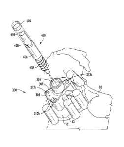
A depth-control pin 400, also referred to as a reaming depth-control
pin, is illustrated in Figure 11. Depth-control pin 400 can be used to control
the depth, orientation and angle of reaming of a glenoid surface or glenoid
face. As illustrated in Figure 11, depth-control pin 400 can comprise a
cylindrical shaft 406 having a first end 402 and a second end 404. First end
402 can comprise a threaded portion 408 configured to threadingly engage
an opening in a glenoid bone (possibly created by a drill bit 350 or similar
boring device), and/or configured to threadingly screw into the surface of a
glenoid bone, i.e. self tapping. Depth-
control pin 400 can in some
embodiments screw into or penetrate a glenoid bone up to a depth equal to
the length of first end 402 and/or the length of threaded portion 408. In
some embodiments, depth-control pin 400 can in some embodiments screw
into or penetrate a glenoid bone up until collar 421 comes into contact with
the glenoid surface, or where the threads end. That is, collar 421 acts as a
depth stop once it reaches the surface of the glenoid. The depth can be
generated by the Glenosys depth-control pin 400. Once depth-control pin
400 is secured to the glenoid via the threaded portion 408, reaming depth is
controlled by the length of section 406 which controls the location of collar
420 in conjunction with the internal mating geometry of a reamer (see, e.g.,
Figure 13B). Length of cylindrical portion 406 and consequently location of
collar 420 can be determined via the preoperative analysis performed by
software as disclosed herein. The reaming depth can be the result of the
software analysis to determine the amount of backside support desired by a
user, e.g. a surgeon. Typically greater than about 80% backside support for
a given implant is desired. More reaming or more depth of reaming can in
some aspects result in a shorter length of section 406, resulting in collar
420
being closer to the glenoid face. Less reaming depth can result in a longer
length of section 406 placing the location of collar 420 farther from the
glenoid face.
Second end 404 of depth-control pin 400 can comprise a cylindrical
shaft configured to receive a glenoid reaming device (see Figures 13A and
- 26 -
CA 02927811 2016-04-15
WO 2015/056097 PCT/IB2014/002759
13B). The cylindrical shaft of second end 404 can engage an internal
diameter and mating geometry of a reamer.
Indented portion 412 can in some embodiments act as a quick
connect mechanism. Of note, indented portion 412 is only exemplary of a
connection mechanism and is optional for depth-control pin 400. Likewise,
in some embodiments, notched portion 410 can be configured to engage a
tool (e.g. guide sleeve 700 in Figure 12B) or drill to apply a rotational
and/or
downward force to cause depth-control pin 400 to engage, i.e. screw into,
the surface of a glenoid bone. In some aspects, notched portion 410,
instead of being a notch, or in addition to the notch, can comprise a hex
head, slot, port or torx head configured to engage or receive a tool capable
of applying rotational and/or downward force to depth-control pin 400. Other
connection mechanisms for depth-control pin 400, and particularly second
end 404, can be used without departing from the scope of the instant
disclosure.
In some embodiments, collar 420 can be located between threaded
first end 402 and receiving second end 404. For example, collar 420 (also
referred to as a shoulder in some aspects, but distinct from shoulder 421)
can be at the top of cylindrical shaft 406 and near the base of second end
404. Collar 420 can act as a stop for a reaming device inserted over
receiving portion 410. That is, collar 420 can control the depth of reaming by
a reaming device when depth-control pin 400 is screwed or otherwise affixed
to a glenoid surface.
Figures 12A and 12B illustrate glenoid placement guide 300 in use, or
aligned with the face of glenoid 12 on scapula 10, with the use of depth-
control pin 400. Figure 12A shows depth-control pin 400 prior to insertion in
central port 306, while Figure 12B shows depth-control pin 400 after
insertion into central port 306 and/or during the threading of depth-control
pin 400 into glenoid surface 12. Note that cylindrical shaft 406 is configured
to slidingly engage the cylindrical opening of the central port 306. In some
aspects, cylindrical shaft 406 has a diameter substantially similar to but
slightly less than the diameter of central port 306.
- 27 -
CA 02927811 2016-04-15
WO 2015/056097 PCT/IB2014/002759
In some embodiments, depth-control pin 400 can be guided through
central port 306 of glenoid placement guide 300 and forced into glenoid
bone 12 using a tool or guide sleeve 700 as depicted in Figure 12B. Guide
sleeve 700 can be patient specific and designed along with glenoid
placement guide 300 and/or depth-control pin 400 during pre-operative
planning as disclosed herein. In some embodiments, an alignment surface
of glenoid placement guide 300, e.g. an upper end of cylindrical housing
307, can act as a depth guide wherein it can be used as an indicator for the
depth of a depth-control pin 400, to thereby achieve the appropriate reaming
depth, such as to achieve about 80% implant support. That is, collar 420 of
depth-control pin 400 can stop or match up with a top rim portion of
cylindrical housing 307 to set the depth of depth-control pin 400. Guide
sleeve 700 can in some aspects be used to engage second end 404 of
depth-control pin 400, such as by engaging notch 410 or other mechanical
linkage, to thereby force, through tapping, pushing and/or turning, depth-
control pin 400 into placement guide 300 such that collar 420 is aligned with
cylindrical housing 307. In some embodiments, once these two surfaces are
flush, depth-control pin 400 can be in its correct depth to control the
preplanned reaming depth.
After depth-control pin 400 is threaded into the surface or face of
glenoid 12 at the desired location on glenoid 12, as controlled by glenoid
placement guide 300, glenoid placement guide 300 can be removed by
pulling it away from, i.e. sliding it off of, depth-control pin 400 such that
depth-control pin 400 remains embedded or screwed in glenoid 12. See
Figure 13A. Glenoid 12 as depicted in Figure 13A is now ready to be
reamed using reaming device 500 guided by depth-control pin 400.
However, before reaming the stability of depth-control pin 400 can be
assessed.
It is possible that depth-control pin 400 can be seated at a pre-
planned depth, as discussed above, and yet it is unstable (or at least not
stable enough to support reaming) once placement guide 300 is removed.
In order to stabilize depth-control pin 400 it can in some embodiments need
to be screwed deeper into glenoid 12. However, doing so alters the depth
- 28 -
CA 02927811 2016-04-15
WO 2015/056097 PCT/IB2014/002759
control aspect of depth-control pin 400 for subsequent reaming. Thus, the
location or height of shoulder 420 must be adjusted or augmented to achieve
the same desired depth control after depth-control pin 400 is further seated
to achieve the necessary stability. In such an embodiment a depth control
augment 600, i.e. a spacer, can be used. See Figures 11 and 12A.
Depth control augment 600 can in some aspects be a washer, ring,
sleeve or cylindrical structure having a substantially similar, or the same,
outside diameter as cylindrical portion 406 of depth-control pin 400, and an
inside diameter sufficient to allow it to slide over second end 404 of depth-
control pin 400. When in use depth control augment 600 can effectively
increase the height of, or raise the location of, shoulder 420. In some
aspects, depth control augment 600 can have a height of about 1 mm, about
2 mm, about 3 mm, about 4 mm, about 5 mm, about 6 mm, about 7 mm,
about 8 mm, about 9 mm, or about 10 mm. When slid over second end 404
of depth-control pin 400 it can be advanced by guide sleeve 700. One or
more depth control augments 600 can be used such that the number of
millimeters depth-control pin 400 is advanced into glenoid 12 beyond that
which was originally intended can be compensated by the addition the one
or more depth control augments 600. For example, if depth-control pin 400
is advanced into glenoid 12 4 mm more than originally intended in order to
achieve sufficient stability one 4 mm depth control augment 600, or two 2
mm depth control augments 600, can be used to achieve the same depth
control for which depth-control pin 400 was designed.
Glenoid 12 as depicted in Figure 13A is now ready to be reamed
using reaming device 500, while being guided by depth-control pin 400.
Reaming device 500 can comprise a shaft 506, reaming head 504, and
connector 502 connection reaming head 504 to shaft 506. Inside head 504
can be a cavity 510 with shoulder 520.
Reaming device 500 can slidingly engage second end 404, i.e. the
receiving portion, of depth-control pin 400 by receiving second end 404 into
cavity 510 of reaming device 500. See Figure 13B. Collar 420 can abut
shoulder 520 in cavity 510 such that reaming device 500 can only slid ingly
engage depth-control pin 400 up to a predetermined depth. That is, collar
- 29 -
CA 02927811 2016-04-15
WO 2015/056097 PCT/IB2014/002759
420 acts as a depth-control device on depth-control pin 400 to limit the
distance reaming device 500 can travel down depth-control pin 400, and by
virtue the depth of the reaming of glenoid 12 caused by reaming face 504.
Thus, in some embodiments a glenoid placement guide is provided,
comprising a hub, one or more radial arms extending substantially
perpendicularly and radially from the hub, one or more peripheral guide
structures affixed to the one or more radial arms, and a central port
comprising a cylindrical opening passing through the hub. Such a glenoid
placement guide can further comprise one or more anchoring pin channels,
wherein each channel can comprise a cylindrical opening passing through
the hub and configured to receive and guide an anchoring pin to an
anchoring location of a glenoid surface. The central port can comprise a
cylindrical opening passing through the hub and configured to receive and
guide a depth-control pin to a predetermined location on a glenoid surface.
The glenoid placement guide can in some aspects comprise a polymeric or
metallic material.
In some aspects, one or more peripheral guide structures are
matched to the surface or rim of a glenoid of a patient to be treated. Such
peripheral guide structures that are matched to the surface of a glenoid of a
patient to be treated are configured to align the glenoid placement guide on
the glenoid. To do this, in some embodiments the terminal end of each
peripheral guide structure can comprise a cupped surface configured to align
with an edge portion or rim of the glenoid surface of the patient to be
treated.
The orientation and alignment of the peripheral guide structures to match the
surface or rim of a glenoid of a patient to be treated is achieved through pre-
operative planning. By doing so the peripheral guide structures orient the
placement guide on the glenoid such that the central port is positioned at a
predetermined or optimal position on the glenoid for placement of a reaming
depth-control pin. Not only is the location of the depth-control reaming pin
controlled by the design of the glenoid placement guide, but the angle,
direction, orientation and depth of the depth-control pin is dictated by the
glenoid placement guide such that once the depth-control pin is affixed to
the glenoid it guides the reaming device to achieve the desired reamed
- 30 -
CA 02927811 2016-04-15
WO 2015/056097 PCT/IB2014/002759
glenoid surface. The depth, angle, orientation and location of the reaming is
all controlled by the precise and predetermined placement of the depth-
control pin, which is dictated by the glenoid placement guide, which is
designed based on pre-operative planning.
The pre-operative planning to match the glenoid guide structure to the
surface or rim of the glenoid can in some embodiments comprise aligning an
anterior edge of a glenoid implant with an anterior edge of a glenoid bone;
adjusting a retroversion of the glenoid implant; adjusting an augmentation of
the glenoid implant; adjusting an inferior tilt of the glenoid implant;
evaluating
bone support for the glenoid implant, wherein an amount of a rear surface of
the glenoid implant that is supported by or touching bone is assessed;
adjusting a medialization of the glenoid implant by assessing the volumetric
amount of bone needed to be removed by reaming, or the minimum total
distance of reaming necessary, in order to optimize the bone to implant
interface; analyzing fixation support in the absence of central pegs that
penetrate a vault medially; analyzing a joint line, comprising comparing an
original joint line and a new joint line, wherein the new joint line is
substantially similar to the original joint line; measuring and matching
widths
of the glenoid implant and the glenoid bone after reaming and aligning
inferior and superior axes of the glenoid implant and bone; assessing and
adjusting as needed a thickness/height of the glenoid implant; assessing and
adjusting as needed a depth of a glenoid fossa; and assessing and adjusting
as needed a thickness of a graft.
Such pre-operative planning to match the guide structures to the
surface of the glenoid can be done virtually based on images taken from the
subject prior to surgery, as discussed further herein. The glenoid placement
guide can then be designing, configured and produced based upon
parameters collected from the pre-operative planning such that the guide
can act to orient a depth-control pin such that it an guide the depth,
orientation, direction, angle and location of a reaming device.
The pre-operative planning that goes into designing the glenoid
placement guide can in some embodiments further comprise taking into
consideration the humeral side of the joint and its impacts on the glenoid.
-31 -
CA 02927811 2016-04-15
WO 2015/056097 PCT/IB2014/002759
For example, the pre-operative planning to match and orient the peripheral
guide structures to the surface of the glenoid can further comprise:
determining a diameter of a humeral head; determining a height of the
humeral head; determining a size of humeral bone implant from Houndsfield
units measured by computed tomography scan; and determining a best fit
size of humeral implant from a range of sizes, wherein the range of sizes is
selected from the group consisting of length of stem, size of humeral stem,
diameter of stem, size diameter of head, height of head, and offset of the
center spherical head compared to the center of the face of the humeral
stem. Moreover, in some aspects, the pre-operative planning to match the
guide structures to the surface of the glenoid can further comprise
identifying
a prosthetic shoulder implant, and identifying a placement position for the
prosthetic shoulder implant, wherein the identification of the prosthetic
shoulder implant and placement position can take into consideration at least
one of the factors selected from the group consisting of adjustments in
humerus stem size, length, head diameter, head height, head offset and
rotation (axial), and/or combinations thereof.
Still yet, in some aspects, the pre-operative planning can comprise:
comparing vectors in three dimensions, wherein the vectors comprise a
distance and direction between tendon and muscle insertions on a scapula
and a humerus of a subject, wherein the vectors measure the distance of
relocation of humeral tuberosity compared to the scapula; determining a
suitable implant based on comparison of the vectors; and designing a
glenoid placement guide based on the comparison of vectors and
determination of implant.
Still yet, in some aspects, the pre-operative planning can comprise:
conducting range of motion analysis, including virtually positioning implants
through extreme ranges of motion to measure impact locations and
compensate for necessary functional range of motion; determining a suitable
implant based on comparison of the vectors; and designing a glenoid
placement guide based on the range of motion analysis and determination of
implant. And in some embodiments the pre-operative planning can
comprise: conducting soft tissue analysis comprising determining key soft
- 32 -
CA 02927811 2016-04-15
WO 2015/056097 PCT/IB2014/002759
tissue insertion points; measuring distances in three dimensions for
comparison to pre-operative conditions; assessing lengths at extreme
ranges of motion, such that total soft tissue length change or contraction is
substantially maintained within anatomical ranges in order to substantially
achieve most common activities of daily living; determining a suitable implant
based on comparison of the vectors; and designing a glenoid placement
guide based on the range of motion analysis and determination of implant.
The pre-operative planning can also comprise in some aspects identifying
procedural risks by determining: whether a glenoid face coverage is
maximized; whether an overhang of the glenoid face is minimized; whether
bone removal on the glenoid face is minimized; whether the glenoid
retroversion is less than about 5 to about 10 degrees; whether seating of the
glenoid implant is greater than about 80% of the implant coverage area;
whether there is minimized penetration of the glenoid cortical wall
anteriorly;
whether there is greater than about 3mm bone thickness behind glenoid;
whether the orientation offset between the native glenoid and implant
superior/inferior axis is less than about 5 degrees; whether the superior or
inferior tilt versus native glenoid is less than 5 degrees; whether there is
an
absence of a humeral head overhang compared to the cut, or prepared
surface of the humeral bone; whether there is less than about 3mm
difference in humeral head diameter between anatomic and implant; whether
there is less than about 1mm difference in humeral head height between
anatomic and implant; and whether there is less than about 2 mm greater
tuberosity to medial head edge in comparison to anatomic; whereby
procedural risks are identified; and designing a glenoid placement guide
based on the identified procedural risks.
In some embodiments, a kit is provided for pre-operatively planned
shoulder surgery, including glenoid reaming. Such a glenoid placement
guide kit can in some embodiments comprise a glenoid placement guide of
claim 1; a depth-control pin; and a reaming device. In some aspects, the kit
can further comprise one or more anchoring pins. In some aspects, the kit
can further comprise a software program or computer readable medium for
conducting the pre-operative analysis and analyzing images of shoulder joint
- 33 -
CA 02927811 2016-04-15
WO 2015/056097 PCT/IB2014/002759
to be treated. In some aspects, instructions for conducting the analysis,
creating a glenoid placement guide and/or using the guide are also provided
in the kit.
In some embodiments, methods of reaming a glenoid bone surface of
a patient in preparation for glenoid surgery are provided. Such methods can
comprise designing and producing a patient-specific glenoid placement
guide, wherein the guide comprises a central port configured to receive a
depth-control pin and guide it to a predetermined location on the glenoid
surface and/or designing and producing, or providing, a depth-control pin.
The methods can further comprise placing a placement guide on a glenoid
surface of the patient, inserting a depth-control pin through the guide
central
port, turning the depth-control pin whereby the pin engages the glenoid
surface, removing the guide from the glenoid surface, whereby the depth-
control pin remains engaged to the glenoid surface, aligning a reaming
device to the glenoid surface by sliding the reaming device over the depth-
control pin, and reaming the surface of the glenoid, whereby the depth and
orientation of the reaming is controlled by the depth-control pin. In some
embodiments, a guide sleeve can be used to adjust and confirm positioning
of the depth-control pin.
In some embodiments, methods of reaming a glenoid bone surface,
including designing and producing a patient-specific glenoid placement
guide comprises pre-operative planning as disclosed herein. For example,
the pre-operative planning can comprise aligning an anterior edge of a
glenoid implant with an anterior edge of a glenoid bone; adjusting a
retroversion of the glenoid implant; adjusting an augmentation of the glenoid
implant; adjusting an inferior tilt of the glenoid implant; evaluating bone
support for the glenoid implant, wherein an amount of a rear surface of the
glenoid implant that is supported by or touching bone is assessed; adjusting
a medialization of the glenoid implant by assessing the volumetric amount of
bone needed to be removed by reaming, or the minimum total distance of
reaming necessary, in order to optimize the bone to implant interface;
analyzing fixation support in the absence of central pegs that penetrate a
vault medially; analyzing a joint line, comprising comparing an original joint
-34 -
CA 02927811 2016-04-15
WO 2015/056097 PCT/IB2014/002759
line and a new joint line, wherein the new joint line is substantially similar
to
the original joint line; measuring and matching widths of the glenoid implant
and the glenoid bone after reaming and aligning inferior and superior axes of
the glenoid implant and bone; assessing and adjusting as needed a
thickness/height of the glenoid implant; assessing and adjusting as needed a
depth of a glenoid fossa; and assessing and adjusting as needed a
thickness of a graft.
In some embodiments, methods of treating a patient, and/or surgical
methods, are provided wherein one or more of the disclosed methods of
analysis and optimization are performed on a patient in need of shoulder or
other joint surgery. In some embodiments, methods of treating a patient are
provided wherein a disclosed method of analysis and optimization is
performed, an optimized guide is designed and created, and one or more
glenoid and/or humeral implants are designed, created, and/or selected. In
some embodiments, a method of treating a patient can comprise utilizing the
pre-operative planning to design and optimize a guide and one or more
glenoid and/or humeral implants, and the use of the guide to surgically
implant the one or more glenoid and/or humeral prosthetic devices.
In some embodiments, a kit is provided wherein the kit can comprise
a set of instructions for performing the disclosed pre-operative planning
methods and analyses. Such a kit can further comprise one or more glenoid
and/or humeral prosthetic devices, wherein the devices can be customizable
or modular in design such that the prosthetic device can be optimized for the
patient based on the pre-operative planning analysis. In some
embodiments, a kit can further comprise a guide for placing a prosthetic
device during shoulder surgery, wherein the guide can be optimized for the
patient based on the pre-operative planning analysis. In some
embodiments, a kit can further comprise a 3-D printing device for producing
a guide and/or one or more glenoid and/or humeral prosthetic devices. In
some embodiments, a kit can further comprise a computer-readable medium
(software) for use in conducting the pre-operative planning, and designing a
guide, glenoid implant and/or humeral implant based on input parameters
gathered during the disclosed methods of analysis.
- 35 -
CA 02927811 2016-04-15
WO 2015/056097 PCT/IB2014/002759
In some embodiments a patient can comprise a mammalian subject.
In some embodiments, the patient can be a human subject, including an
adult, adolescent or child.
While the following terms are believed to be well understood by one of
ordinary skill in the art, the following definitions are set forth to
facilitate
explanation of the presently disclosed subject matter.
Unless defined otherwise, all technical and scientific terms used
herein have the same meaning as commonly understood to one of ordinary
skill in the art to which the presently disclosed subject matter belongs.
Although any methods, devices, and materials similar or equivalent to those
described herein can be used in the practice or testing of the presently
disclosed subject matter, representative methods, devices, and materials are
now described.
Following long-standing patent law convention, the terms "a" and "an"
mean "one or more" when used in this application, including the claims.
Unless otherwise indicated, all numbers expressing quantities of
ingredients, reaction conditions, and so forth used in the specification and
claims are to be understood as being modified in all instances by the term
"about". Accordingly, unless indicated to the contrary, the numerical
parameters set forth in this specification and attached claims are
approximations that can vary depending upon the desired properties sought
to be obtained by the presently disclosed subject matter.
As used herein, the term "about," when referring to a value or to an
amount of mass, weight, time, volume, concentration or percentage is meant
to encompass variations of in some embodiments 20%, in some
embodiments 10%, in some embodiments 5%, in some embodiments
1%, in some embodiments 0.5%, and in some embodiments 0.1% from
the specified amount, as such variations are appropriate to perform the
disclosed method.
As used herein, the term "and/or" when used in the context of a listing
of entities, refers to the entities being present singly or in combination.
Thus,
for example, the phrase "A, B, C, and/or D" includes A, B, C, and D
-36-
CA 02927811 2016-04-15
WO 2015/056097 PCT/IB2014/002759
individually, but also includes any and all combinations and subcombinations
of A, B, C, and D.
The term "comprising", which is synonymous with "including,"
"containing," or "characterized by" is inclusive or open-ended and does not
exclude additional, unrecited elements or method steps. "Comprising" is a
term of art used in claim language which means that the named elements
are present, but other elements can be added and still form a construct or
method within the scope of the claim.
As used herein, the phrase "consisting of" excludes any element,
step, or ingredient not specified in the claim. When the phrase "consists of"
appears in a clause of the body of a claim, rather than immediately following
the preamble, it limits only the element set forth in that clause; other
elements are not excluded from the claim as a whole.
As used herein, the phrase "consisting essentially of" limits the scope
of a claim to the specified materials or steps, plus those that do not
materially affect the basic and novel characteristic(s) of the claimed subject
matter.
With respect to the terms "comprising", "consisting or, and "consisting
essentially of", where one of these three terms is used herein, the presently
disclosed and claimed subject matter can include the use of either of the
other two terms.
As used herein, "significance" or "significant" relates to a statistical
analysis of the probability that there is a non-random association between
two or more entities. To determine whether or not a relationship is
"significant" or has "significance", statistical manipulations of the data can
be
performed to calculate a probability, expressed as a "p value". Those p
values that fall below a user-defined cutoff point are regarded as
significant.
In some embodiments, a p value less than or equal to 0.05, in some
embodiments less than 0.01, in some embodiments less than 0.005, and in
some embodiments less than 0.001, are regarded as significant.
Accordingly, a p value greater than or equal to 0.05 is considered not
significant.
- 37 -
CA 02927811 2016-04-15
WO 2015/056097
PCT/IB2014/002759
It will be understood that various details of the presently disclosed
subject matter may be changed without departing from the scope of the
presently disclosed subject matter. Furthermore, the foregoing description is
for the purpose of illustration only, and not for the purpose of limitation.
-38-