Note: Descriptions are shown in the official language in which they were submitted.
CA 02927831 2016-04-18
WO 2015/054836
PCT/CN2013/085287
1
Subframe and Method for Reinforcing the Same
FIELD OF THE INVENTION
The present invention generally relates to a reinforced vehicle subframe and
also to a
method for reinforcing such vehicle subframe.
BACKGROUND
In modern automotive vehicles, subframes are widely used for isolating
vibration and
increasing connection strength of other relevant parts of the vehicles, such
as engines,
powertrains, suspension systems or the like. For example, a subframe is
usually
provided in an automotive vehicle. The subframe is attached to the vehicle
body, and is
mounted with a suspension system thereon. In this way, the suspension system
is
associated with the vehicle body such that less vibration can be transmitted
from an
engine of the vehicle or roads to the suspension system or a passenger
compartment of
the vehicle. Since the suspension system is connected indirectly with the
vehicle body
itself via the subframe, the suspension system can be more reliably secured
relative to
the vehicle body.
The subframe is usually made by metal-sheet parts. In order to reduce the
total weight
of the vehicle, the subframe should be light. For example, aluminum alloy or
titanium
alloy or the like can be used to manufacture the subframe. Further, in order
to enable the
subframe to be lighter, the thickness of the metal-sheet part of the subframe
is designed
to be as little as possible. However, if the metal-sheet part of the subframe
is too thin,
the stiffness of the subframe itself will be insufficient to bear the
suspension system and
attach to the vehicle body. Therefore, it is desirable to find a way of
reducing the weight
of the subframe itself while enabling it to have sufficient stiffness.
Patent publication EP2165919 discloses a reinforced structure including a
structural
component (2) and a reinforcing part (4) that is arranged in a cavity of the
structural
component, wherein the reinforcing part (4) comprises a support part (5) and
connection
means (6) which can be a foamed material. However, this reference does not
concern
CA 02927831 2016-04-18
WO 2015/054836
PCT/CN2013/085287
2
how to lighten and strengthen the subframe. Rather, this reference concerns
how to
optimize use of the activatable foamed material. Specifically, the
optimization is
achieved by using a lesser amount of the activatable foamed material at
positions with
high deformation than at positions with low deformation of the component.
Patent publication U520120315414 discloses a composite component made up of a
shell at least locally and peripherally delimiting a space and also discloses
a structural
component with structural material being provided at least locally between the
shell and
the structural component. This reference does not concern how to lighten and
strengthen
the subframe either.
Patent publication W02012140154 generally concerns how to reinforce attachment
of a
subframe to a mainframe of a vehicle. This reference does not concern how to
lighten
and strengthen the subframe itself.
As mentioned above, the subframe of the vehicle should be designed to have
high
stiffness and low weight such that the vehicle can run more fuel-efficiently
and can be
manufactured at lower costs. To this end, the subframe should be made by
reducing use
of metal-sheet parts and by adding other alternative parts. However, it is
difficult and
unknown to determine how to reduce the use of metal-sheet parts with
maintaining the
stiffness of the subframe.
SUMMARY OF THE INVENTION
It is an object of the present invention to propose a subframe for a vehicle
and a method
for reinforcing the subframe, such that the subframe is more lightweight and
stiff, and
can be manufactured at lower costs.
In one aspect of the present invention, a method for reinforcing a vehicle
subframe
comprising one or more hollow metal-sheet parts is provided, wherein the
method
comprises:
a step of determining at least one area on the hollow metal-sheet part of the
subframe
with respect to specified conditions;
a step of preparing a reinforcement part which is able to be inserted in the
hollow
CA 02927831 2016-04-18
WO 2015/054836
PCT/CN2013/085287
3
metal-sheet part of the subframe at said area, wherein the reinforcement part
comprises
a lightweight carrier for supporting the metal-sheet part and a pre-foam of a
foam
material which is able to expand after being heated, wherein the lightweight
carrier
comprises at least one hollow chamber and wherein the pre-foam is isolated
from the at
least one hollow chamber and is distributed at least partly on the periphery
of the carrier;
and
a step of installing the reinforcement part within the metal-sheet part of the
subframe at the determined area and supplying heat to the pre-foam such that
it expands
to secure the reinforcement part within the subframe.
Preferably, the step of determining the area is achieved by topology
optimization
technology in a computer.
Preferably, the area is defined as an area of the metal-sheet part of the
subframe in
which the most stress or failure possibly occurs in the case that a static or
dynamic load
is applied to the subframe.
Preferably, the applied load is substantially the same as that applied to a
subframe of an
actually running vehicle.
Preferably, the metal-sheet part of the subframe is thinned at the determined
area.
Preferably, the lightweight carrier is made of Polyamide.
Preferably, the carrier is made by a plurality of thin-wall sections for
forming said at
least one hollow chamber.
Preferably, in the step of preparing the reinforcement part, the carrier is
placed in a mold
which is manufactured similarly to the determined area, and then the pre-foam
is
injected into the mold such that it is able to distribute at least partly on
the periphery of
the carrier.
Preferably, heat is supplied to the pre-foam after the reinforcement part is
transported
through a coating line designed for the subframe.
CA 02927831 2016-04-18
WO 2015/054836
PCT/CN2013/085287
4
In another aspect of the present invention, a vehicle subframe is provided,
the subframe
comprising one or more hollow metal-sheet parts, wherein the subframe is
reinforced by
a reinforcement part in at least one predetermined area thereof, the
reinforcement part
comprises a lightweight carrier for supporting an inner surface of the metal-
sheet part
and a pre-foam of a foam material which is able to expand after being heated,
the carrier
comprises at least one hollow chamber enabling the carrier to be light, the
pre-foam is
isolated from said at least one hollow chamber and is located at least partly
on the
periphery of the carrier, after the reinforcement part is arranged within the
metal-sheet
part at the area, heat is supplied to the pre-foam such that it expands to
secure the
reinforcement part within the subframe.
Preferably, the area is determined by topology optimization technology via a
computer.
Preferably, the area is defined as an area of the metal-sheet part of the
subframe in
which the most stress or failure possibly occurs in the case that a static or
dynamic load
is applied to the subframe.
Preferably, the applied load is substantially the same as that applied to a
subframe of an
actually running vehicle.
Preferably, the metal-sheet part of the subframe is thinned at the determined
area.
Preferably, the lightweight carrier is made of Polyamide.
Preferably, the carrier is made by a plurality of thin-wall sections for
forming said at
least one hollow chamber.
Other individual features or features which are combined with other features
so as to be
considered as belonging to the characteristics of the present invention will
be described
in the attached claims.
The configuration of the present invention as well as other objectives and
beneficial
effects thereof will be well understood by a description of preferred
embodiments in
CA 02927831 2016-04-18
WO 2015/054836
PCT/CN2013/085287
accompany with the drawings.
BRIEF DESCRIPTION OF THE DRAWINGS
5 In order to provide further explanations of the present invention, the
drawings, as a part
of the description, illustrate preferred embodiments of the present invention,
and they
are used to explain principles of the present invention together with the
description. In
the drawings:
Figure 1 schematically shows a perspective view of a computing model of a
subframe
adapted to an automotive vehicle;
Figure 2 schematically shows an exploded and perspective view of a
reinforcement part
according to an embodiment of the present invention;
Figure 3 schematically shows an enlarged sectional view of the reinforcement
part of
figure 2; and
Figure 4 schematically shows a flow chart, illustrating a method according to
the
present invention for reinforcing the subframe illustrated in figure 1.
DETAILED DESCRIPTION OF THE INVENTION
In the attached drawings, the same components are indicated by the same
reference
numerals.
Figure 1 schematically shows a subframe 1 adapted to an automotive vehicle. It
should
be noted that this subframe 1 is illustrated only as an example for the
purpose of
explaining the basic principle of the present invention. The subframe adapted
to the
automotive vehicle can be configured in various forms. The principle of the
present
invention is not limited by any illustrative embodiments which will be
described below.
That is, it is well-known for a person skilled in the art after reading the
context of the
present invention that the principle or method explained below is applicable
for the
subframe of any type.
CA 02927831 2016-04-18
WO 2015/054836
PCT/CN2013/085287
6
The subframe 1 generally comprises a plurality of metal-sheet parts. For
example, each
part can be made of lightweight metal, such as aluminum alloy, titanium alloy
or the
like. In order that the subframe 1 is as light as possible, the part is
usually shaped to be
hollow. In figure 1, four metal-sheet parts are illustrated, which are
assembled together
to form the subframe 1 as a substantially rectangular shape. For instance,
these
metal-sheet parts can be welded or riveted at their respective ends. It is
appreciated that
the shape of the subframe 1 can be adapted to various requirements of the
vehicle.
In the prior art, researches mainly focus on how to reinforce attachment areas
of the
subframe 1 to other vehicle components. However, the present invention
concerns how
to reinforce the subframe 1 itself. To this end, topology optimization is
introduced into
design of the subframe.
In the mechanical design field, the topology optimization belongs to
technology which
is widely used to model, simulate and analyze a mechanical component by means
of a
computer. Many commercial softwares, such as ANSYS, HYPEWORK, ABAQUS are
available in the market to achieve the topology optimization. It should be
understood
that the present invention focuses not on algorithms of modeling, simulating
and
analyzing the subframe by the computer; but on application of the topology
optimization. Therefore, the context of the present invention does not
describe any
concrete algorithm. It is assumed that knowledge relating to the concrete
algorithm is
well-known by the skilled person in the art who can use any one of said
softwares
skillfully.
When a static or dynamic load is applied to the subframe 1, different stresses
may occur
in difference areas of the subframe. However, according to our idea, it is
unnecessary to
reinforce the whole subframe so as to manufacture the subframe simply. The
introduced
topology optimization is used to find one or more areas of the subframe which
need be
reinforced effectively.
For instance, before the subframe 1 is manufactured in a workshop, it is
created as a
computing model in a computer, for example via ANSYS. Then, on the basis of
the
topology optimization technology, the computing model of the subframe 1 is
analyzed
CA 02927831 2016-04-18
WO 2015/054836
PCT/CN2013/085287
7
in the computer. For instance, loads which are similar as those occurring in
an actually
running vehicle can be applied to the computing model. After computation, one
or more
areas of the subframe in which the largest stress and/or failure will most
likely occur
can be determined. As an example, in figure 1, an area 1.1 is regarded as such
an area of
the subframe 1 in which the largest stress and/or failure will most likely
occur. That is, it
is determined that the area 1.1 of the subframe 1 should be reinforced.
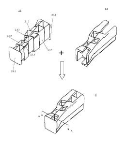
Figure 2 schematically shows an exploded and perspective view of the area 1.1
of the
subframe 1 in which a reinforcement part 2 according to an embodiment of the
present
invention is used to reinforce this area. The reinforcement part 2 is received
at the area
1.1 in a hollow interior of the metal-sheet part of the subframe 1.
According to the present invention, the reinforcement part 2 is substantially
comprised
of a Polyamide (PA) carrier 2.1 and a pre-foam 2.2 of a foam material. The pre-
foam 2.2
is secured in a solid state partly on a surface of the PA carrier 2.1. The
reinforcement
part 2 is inserted as a whole in the hollow interior of the subframe 1,
especially in the
hollow interior of the metal-sheet of the subframe at the area 1.1 such that
the pre-foam
2.2 may contact tightly with an inner surface of the area 1. Alternatively, it
is
appreciated that the carrier can be any lightweight carrier made of material
lighter and
stiffer than the metal-sheet part.
The PA carrier 2.1 is for example formed as a shape illustrated in figure 2.
In this figure,
the PA carrier 2.1 is formed by two parallel end sections 2.1.1 and a
plurality of
thin-wall sections located between the two end sections 2.1.1. Alternatively,
each end
section 2.1.1 is sized such that their edges may contact firmly with the inner
surface of
the metal-sheet part. Furthermore, the longitudinal distance between the two
end
sections 2.1.1 is substantially equal to the longitudinal length of the area
1.1.
In said thin-wall sections, some thin-wall sections 2.1.2 are parallel with
the two end
sections 2.1.1, two thin-wall sections 2.1.3 (only one of them is visible in
figure 2) are
perpendicular relative to the first thin-wall sections 2.1.2 and the end
sections 2.1.1, and
two thin-wall sections 2.1.4 are sections delimiting the PA carrier 2.1
laterally. Viewed
towards the end section 2.1.1, all the thin-wall sections are located in the
periphery of
the end section 2.1.1, and especially the thin-wall section 2.1.4 is spaced
from the
CA 02927831 2016-04-18
WO 2015/054836
PCT/CN2013/085287
8
relevant edge of the relevant end section 2.1.1. In this way, the PA carrier
2.1 can be
provided with at least one hollow chamber. For example, in the illustrated
embodiment,
a plurality of hollow chambers 2.1.5 are formed alternately between the thin-
wall
sections respectively. Therefore, the PA carrier 2.1 can be manufactured as
light as
possible and at the same time can provide a sufficient support for the metal-
sheet part of
the subframe 1. These hollow chambers 2.1.5 can be formed so as to communicate
with
each other.
In the illustrated embodiment, between two adjacent hollow chambers 2.1.5, a
thin
recess can be formed by a further thin-wall section 2.1.6 which is integrally
formed with
the respective thin-wall sections forming the two hollow chambers. The thin
recess is
used to receive the pre-foam 2.2.
Figure 2 shows a state of only the PA carrier 2.1, a state of only the cured
pre-foam 2.2
and a combined state of the PA carrier 2.1 and the pre-foam 2.2. For clarity,
the
respective metal-sheet part is omitted in this figure. It can be seen that the
hollow
chambers 2.1.5 are left in the finished reinforcement part 2 such that it is
still light and
stiff. The reinforcement part 2 will be provided in the combined state of the
PA carrier
2.1 and the pre-foam 2.2. After the reinforcement part 2 is inserted, at the
area 1.1, into
the metal-sheet part of the subframe 1, the area 1.1 will be heated. After
being heated,
the pre-foam 2.2 will expand such that the reinforcement part 2 can be secured
reliably
in the metal-sheet part of the subframe 1. To this end, the pre-foam 2.2 cited
in the
present invention can be any suitable structural pre-foam which is able to
expand after
being heated.
Figure 3 schematically shows a cross-sectional view obtained along an arrow A-
A of
figure 2. It can be seen that, in order to ensure that the stiffness of the PA
carrier 2.1 is
sufficient, the two thin-wall sections 2.1.3 extend perpendicularly relative
to each other.
The pre-foam 2.2 is filled between the relevant thin-wall sections of the PA
carrier 2.1
and the inner surface of the metal-sheet part of the subframe 1 so as to
secure the PA
carrier 2.1 with the metal-sheet part firmly. Alternatively or preferably, it
is also
appreciated that the pre-foam can be filled into the hollow chambers so as to
secure the
carrier to the metal-sheet part of the subframe.
CA 02927831 2016-04-18
WO 2015/054836
PCT/CN2013/085287
9
Usually, if the area 1.1 is regarded as an area in which failure may occur,
the
metal-sheet part of the subframe 1 at this area will conventionally be
thickened. Instead,
in order to reduce the total weight of the subframe 1, the metal-sheet part of
the
subframe 1 at this area which is provided with the reinforcement part 2
according to the
present invention can be thinned. Therefore, the present invention proposes a
new
technical solution of lightening the subframe for the vehicle, by which the
total weight
of the subframe can be reduced and it can be manufactured at lower costs.
Although a structure illustrated by figure 2 is used as a concrete example to
explain the
reinforcement part 2, it should be understood that the reinforcement part 2 is
not limited
to this structure. Alternatively, more thin-wall sections 2.1.3 can be
provided in the PA
carrier 2.1 at various orientations such that they may provide suitable and
reliable
support for the metal-sheet part of the subframe 1. Furthermore, the
reinforcement part
2 can be alternatively formed as a honeycomb-shaped structure, which has
recesses on
its periphery. The recesses can be used to cooperate with the inner surface of
the
metal-sheet part of the subframe to form cavities in which the pre-foam can be
filled.
Finally, figure 4 is a flow chart, schematically showing a method according to
the
present invention for reinforcing a subframe for a vehicle. The method
generally
comprises the following steps.
Step 1: Creating a computing model of a subframe for a vehicle.
In this step, any commercially available computer-aided engineering (CAS)
software
can be adopted in a computer. Therefore, the subframe can have any shape
meeting
requirements of manufacturing the vehicle.
Step 2: Analyzing the computing model of the subframe and determining one or
more
areas in which failure possibly occurs.
For example, the area can be defined as an area in which the largest stress or
a break
may occur when a simulating static or dynamic load is applied on the subframe.
The
load can be simulated as a load which may occur actually in the subframe.
CA 02927831 2016-04-18
WO 2015/054836
PCT/CN2013/085287
Step 3: Designing and manufacturing a reinforcement part for the area found in
step 2.
Since different vehicles are equipped with different subframes and the same
subframe
may be shaped variously at different areas, the reinforcement part should be
customized
5 to the area found in step 2. However, no matter how the area of the
subframe is shaped,
the basic principle of designing the reinforcement part is the same as that
illustrated in
figures 2 and 3 as explained above. That is, the reinforcement part should
comprise a
lightweight carrier for supporting a metal-sheet part of the subframe at the
area and a
pre-foam for securing the carrier to the metal-sheet part. The lightweight
carrier is first
10 manufactured. Then it is placed in a mold which is previously produced
similarly to the
determined area. The PA carrier should be configured as a hollow structure and
have
recesses on its periphery such that, after the PA carrier is arranged in
place, the pre-foam
is injected into the recesses in a fluid state and then the pre-foam covers at
least partly
on the periphery of the carrier. By this way, the reinforcement is
manufactured. It is
appreciated that the pre-foam can be provided on the periphery of the carrier
by other
suitable high molecular polymer processing technologies.
Alternatively, in this step, the same or other commercially available CAE
softwares can
be adopted for verifying whether the area of the subframe is reinforced by the
reinforcement part sufficiently or not. Further, such design and verification
can be
achieved in the case that the metal-sheet part of the subframe is thinned at
the given
area.
Step 4: Installing the reinforcement part based on results of step 3 into the
subframe.
In this step, the reinforcement part is first inserted into the hollow
interior of the
metal-sheet part of the subframe at the determined area. Then, the subframe
together
with the reinforcement part would be transported through a coating line
designed for the
subframe. In the coating line, the subframe would undergo processes such as
painting,
baking and so on. During baking, heat is supplied to the pre-foam such that it
expands
and thus the reinforcement part is secured reliably within the metal-sheet
part of the
subframe. It is appreciated that heat supplying is not limited to be achieved
only in the
coating line. Alternatively, an additional and independent step can be
provided for
heating the subframe, especially the area to enable the pre-foam to expand.
CA 02927831 2016-04-18
WO 2015/054836
PCT/CN2013/085287
11
Although the present invention is shown and explained by specific embodiments,
the
present invention is not limited by these explained particulars. Contrarily,
various
modifications of the present invention are possible within the scope of
attached claims
and their equivalents.