Note: Descriptions are shown in the official language in which they were submitted.
CA 02927942 2016-04-18
WO 2015/076981 PCMJS2014/062325
METHOD AND SYSTEM FOR IMPREGNATING FIBERS TO FORM A PREPREG
BACKGROUND
Prepreg composite materials have been widely used in various high-performance
structures, such as aircraft and automobile components, and sport equipment
(e.g., fishing
rods, golf club shafts, badminton rackets, tennis rackets, etc.). A prepreg is
a fiber
reinforcement that is pre-impregnated with a matrix resin, typically a
thermoset resin. The
fibers reinforce the matrix resin, bearing the majority of the load supported
by the prepreg
material, while the resin matrix bears a minority portion of the load
supported by the prepreg
material and also transfers load from broken fibers to intact fibers. In this
manner, the
prepreg material can support greater loads than either the matrix resin or
fibers can support
alone. Furthermore, by tailoring the reinforcing fibers in a particular
geometry or orientation,
a composite material can be efficiently designed to minimize weight and volume
while
maximizing strength.
Prepregs may be manufactured by impregnating a web of continuous fibers or a
fabric with a matrix resin, creating a pliable and tacky sheet of material.
During
impregnation, the reinforcing fibers are impregnated with the matrix resin in
a controlled
fashion. The precise specification of the fibers, their orientation and the
formulation of the
resin matrix can be specified to achieve the optimum performance for the
intended use of
the prepregs. The mass of fibers per square meter can also be specified
according to
requirements.
The term "impregnate" refers to the introduction of a matrix resin to
reinforcement
fibers so as to partially or fully encapsulate the fibers with the resin. The
impregnation
process controls the amount of resin inside the fiber bed and at the surface
of the fiber bed.
Furthermore, the resin impregnation level impacts the methods used to assemble
the
finished composite part and the part's quality. The matrix resin for making
prepregs may
CA 02927942 2016-04-18
WO 2015/076981 PCT/US2014/062325
take the form of resin films or liquids. Typically, impregnation is
facilitated by the application
heat and/or pressure. The resulting prepregs produced from the prepreg
fabrication process
is in an uncured or curable state (i.e., not hardened) and may be frozen in
order to inhibit the
polymerization of the resin. For manufacturing composite parts from prepregs,
the cold
prepregs are thawed to room temperature, cut to size, and assembled on a
molding tool
through various methods, such as hand layup, Automated Tape Layup (ATL), and
Advanced
Fiber Placement (AFP). The prepreg material for each assembly method requires
different
levels of impregnation and different levels of tack. Level of "tack" refers to
how well prepregs
stick to one another and to a tool surface. For example, for hand layup, there
is less need
for high level of impregnation and greater need for tack while with AFP the
fiber bed requires
much higher levels of impregnation. Once in place, the prepregs are
consolidated and cured
under pressure to achieve the required fiber volume fraction with minimal
voids.
Currently, many conventional methods for impregnating continuous fiber
material
involve the use of static pressure-applying mechanism. Roller nips, for
example, have been
used to supply pressure from a fixed position in space while a continuous web
moves
through the static nips. These conventional processes are generally limited to
a web speed
of 1 to 4 m/min for high impregnation of thick resin films and fiber
materials. They are also
limited in their operating temperatures as higher temperatures tend to cause
problems with
premature curing of the resin or swelling in the case of thermoplastic resin.
Essentially, what
dominates the prepreg world are the fundamental physical limitations outlined
in Darcy's law:
the rate of fluid flow is a function of the pressure supplied, the thickness
of the body, the
permeability of the body of interest and the viscosity of the fluid. In the
case of carbon fiber
webs, the body has a dynamic permeability and the fluid has a dynamic
viscosity, i.e.
viscosity which changes with shear rate and temperature. This law cannot be
over-ridden.
Different fiber materials, different resins, different pressures and web
speeds all change the
shape and movement of the function but do not change the law. So a static nip
or a belt
under certain pressures and temperatures will always limit the production
speed of the
2
CA 02927942 2016-04-18
WO 2015/076981 PCT/US2014/062325
material. If the web is moving too fast, a static nip cannot press enough
resin into the fiber
web. If the temperature applied to the resin is too hot, the material will
distort and will be
ruined, and if too cold, there is insufficient force to press the resin into
the fiber web.
In light of the issues discussed above, there remains a need for an improved
resin
impregnation technique that can increase prepreg production rate without
sacrificing the
control of impregnation level.
BRIEF DESCRIPTION OF THE DRAWINGS
FIG. 1 illustrates the general concept of Relative Speed Impregnation
technique
according to the present disclosure.
FIG. 2 illustrates a conventional technique of applying static pressure nip to
affect
impregnation.
FIG. 3 is a graph showing the relationship between pressure-at-time and
relative
velocity (Vrel) between a moving web material and the pressure nip applied
during
impregnation.
FIG. 4 shows an embodiment of a prepreg fabrication system.
FIG. 5 shows an embodiment a static pressure applicator for pressing an idler
roller
against a web material.
FIG. 6 shows another embodiment of a static pressure applicator for pressing
an idler
roller against a web material.
FIG. 7 illustrates the roller chain progression under static pressure
applicators
according to an embodiment of applying pressure against a moving web material.
DETAILED DESCRIPTION
Disclosed herein is a prepreg fabrication method with an improved resin
impregnation technique ¨ referred herein as relative speed impregnation (RSI).
The
impregnation technique disclosed herein is related to resin film impregnation
in which at
3
CA 02927942 2016-04-18
WO 2015/076981 PCT/US2014/062325
least one resin film is pressed against each of the top and bottom surfaces of
a continuous
fibrous web to produce a continuous prepreg, in which the fibrous material is
embedded
within a matrix resin. The fibrous web is composed of reinforcement fibers and
may be in
the form of unidirectional fibers or a fabric (woven or nonwoven). The term
"impregnate" as
used herein refers to the introduction of a curable matrix resin to
reinforcement fibers so as
to partially or fully encapsulate the fibers with the matrix resin.
An objective of the RSI technique is to produce the fastest prepreg production
speed
with the least fiber bed distortion and minimum pressure to achieve a desired
impregnation
level. To that end, an impregnation zone configuration is designed so that a
web of resin-
fiber material moving at a first velocity (Vw), often called "line speed,"
through an
impregnation zone while pressure is applied by at least one moving pressure
nip moving at a
second velocity (Vn) and in the same direction as that of the moving web. The
moving
pressure nip is formed between a moving pressure roller and a moving surface
supporting
the web material. The moving surface is configured so as to mitigate the
friction forces to
the contacting surface of the web material. According to a preferred
embodiment, the
moving surface is part of a rotating drum with a relative large cross-
sectional diameter. Vw
and Vn are the operating velocities relative to a fix point on the ground. Vw
is different from
Vn, whereby the difference between V,,,,, and Vn is the relative velocity
(Vrel) between the web
material and the pressure nip. The level of impregnation is affected by the
relative velocity
(Vrel).
FIG. 1 illustrates the general concept of the RSI technique. In this figure,
the web
material W (composed of a layer reinforcement fibers sandwiched between two
resin films)
is moving at a line speed of 21 m/min while pressure is applied by the moving
pressure nip
formed between rollers 1 and 2, each roller rotating about its own central
axis. The pressure
nip is moving in the same direction as that of the web material W at a
velocity of 18 m/min.
This means that the relative velocity (Vrel) between the web material W and
the moving
pressure nip is 3 m/min. As such, the line speed (i.e. production rate) of the
web material is
4
CA 02927942 2016-04-18
WO 2015/076981 PCT/US2014/062325
7 times that of the relative velocity (Vrei). The line speed speeds as
discussed in the present
disclosure may be measured using conventional speed sensing devices such as
tachometers.
In contrast, conventional prepreg fabrication methods typically involve
applying static
pressure nip to affect impregnation as illustrated in FIG. 2. In FIG. 2, the
pressure nip
formed by rollers 1 and 2 is stationary (i.e., velocity is 0 m/min) as the web
material is
passing through the nip. In this case, the line speed of the web material is
the same as the
relative velocity (Vrei), and consequently, the line speed of the web material
is limited to the
relative speed (Vrei). As such, in order to achieve the same level of
impregnation at Vre, of 3
m/min as in the RSI technique, the line speed of the web material is limited
to 3 m/min.
The advantage of the RSI process is that the physics of impregnation is
decoupled
from the line speed of the web material, thereby enabling a significantly
higher prepreg
production rate at identical levels of impregnation as compared to
conventional impregnation
methods using static pressure nips or belts. These conventional methods
generally require
immense forces and complicated control systems.
In order to provide impregnation, pressure-at-time is required ¨ the pressure
applied
to web material (not too high or too low) and time provided by slow speed.
Pressure-at-time
may be calculated as P/ Vrei ¨ the linear force (P) applied to the web
material divided by the
relative velocity (Vrei), and is measurable in units of Pascal-second (Pass),
equivalent to
kg/m/s. The linear force (P) is the downward force per linear width, e.g.
pounds per inch
(PLI) or Newtons per meter (N/m), exerted by the pressure roller (upper roller
1, FIG. 1),
which is measured along the width of the web material. The relationship
between pressure-
at-time and relative velocity Vrei is hyperbolic as illustrated in FIG. 3. As
Vrei is decreased,
pressure-at-time dramatically increases. And the impregnation level goes up
with pressure-
at-time. As such, it is desirable to keep Vrei as low as possible. The optimum
\ire, is
CA 02927942 2016-04-18
WO 2015/076981 PCT/US2014/062325
dependent on the resin properties (e.g. viscosity) and permeability of the
fiber web (e.g.
openings or voids in the fiber layer, spacing/interstices between fibers,
etc.).
According to a preferred embodiment, the RSI process is carried out by moving
a
web material (which is composed of a fiber layer sandwiched between two resin
films)
through an impregnation assembly having one or more moving pressure nips
applying
pressure-at-time of up to 10 MPa-s, or up to 7 MPa.s in certain embodiments,
to achieve the
required level of impregnation, e.g. up to 100% impregnation level. The
pressure-at-time in
this context refers to that applied by the entire impregnation assembly. The
level of
impregnation refers to how far the resin has penetrated through the thickness
of the fiber
layer. If the resin has penetrated through the entire thickness of the fiber
layer, filling all
interstices/gaps/openings therein, and there is substantially no resin-free
region at the center
of the fiber layer, then 100% or full impregnation has been achieved. Because
impregnation
is decoupled from the line speed of the web material, the line speed is
limited only by the
size of the manufacturing equipment. As an example, in conventional
impregnation methods
using static-nip arrangement, s-wraps, or pressure belts, the line speed of a
high viscosity
web material with a thick fiber bed may be up to 15 ft/min (3 m/min), while
the RSI process is
capable of increasing the line speed by more than 10 fold.
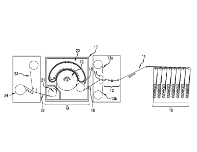
An embodiment of a prepreg fabrication system with means for implementing the
RSI
process is shown in FIG. 4. Referring to FIG. 4, the prepreg fabrication
process starts with
conveying continuous fiber bundles 11 from a fiber supply unit 10 to a fiber
spreading
section 12. The fiber supply unit 10 includes a plurality of spools for
winding the fiber
bundles and creels for supporting the spools. Each fiber bundle is composed of
a plurality of
fiber filaments. The fiber spreading section 12 is equipped with suitable
means for
spreading the fiber bundles before contacting the fibers with the resin films.
As such, the
spread fibers appear as a sheet of unidirectionally aligned fiber filaments
with small spacing
between adjacent filaments. Guide rollers are positioned along the traveling
path of the fiber
bundles to guide the fiber bundles and to provide the necessary tension
therein. The
6
CA 02927942 2016-04-18
WO 2015/076981 PCT/US2014/062325
spread fiber filaments from the fiber spreading section 12 are then combined
with an upper
resin film 13a and a lower resin film 13b with the aid of rollers 14 so that
the fiber filaments
are sandwiched between the two resin films. Each resin film is supplied by its
own supply
roll and the surface that is not in contact with the fiber filaments is
covered by a release
paper. The resulting web material 15 is next conveyed through an impregnation
zone 16,
which includes an insulated chamber 17 enclosing a pre-heating roll 18, a
rotating drum 19,
an endless roller chain 20 of linking idler rollers, and a thermally-isolated,
chill roll 21.
The pre-heating roll 18 is positioned at the beginning of the impregnation
zone and
upstream of the drum 19. Prior to entering the impregnation zone 16, the resin
films are in a
solid state and may be kept at a cold temperature during storage in order
maintain their
solidified state. Immediately after the web material 15 enters the chamber 17,
the pre-
heating roll 18 applies heat to the web material in an amount sufficient to
decrease the resin
viscosity so that the resin is softened but not high enough to cause
substantial curing of the
resin.
The chamber 17 is equipped with suitable temperature control mechanisms (not
shown), for example, infra-red sensors mounted onto the sidewall of the
chamber 17, to
provide temperature data for the web material, the drum 19, the roller chain
20 as well as the
tension of the web material entering and exiting the chamber 17. According to
one
embodiment, the temperature in chamber 17 may be maintained within the range
of 50 C to
120 C, which is sufficient for most commercially available resin systems.
During
impregnation, the resin penetrates into the interstices/spacing between the
fiber filaments.
The resin viscosity is stabilized and maintained at a desired level as the web
material travels
through the entire impregnation zone with the aid of the temperature control
mechanism in
the chamber 17. According to one embodiment, the viscosity of the resin during
impregnation is dependent upon the target resin system but may range from 0.03
Pa.s to
7000 Pa.s.
7
CA 02927942 2016-04-18
WO 2015/076981 PCT/US2014/062325
The drum 19 provides a moving support surface for the web material during
impregnation and cooperates with the roller chain 20 to establish moving
pressure nips
through which the web material passes. The web material wraps around a portion
of the
drum's outer surface as the drum rotates. The large cross-sectional diameter
of the drum 19
provides a physical platform for handling the nip pressures with the least
amount of
curvature possible. The roller chain 20 is configured to carry a series of
closely spaced, idler
rollers having elongated, cylindrical bodies with lengths extending
transversely to the travel
direction of the web material, each idler roller being freely rotatable about
its own axis. The
idler rollers are linked to each other by suitable linking mechanisms, for
example, each idler
roller may have a pin (a connecting mechanism) at one axial end connected to a
corresponding link in an endless chain of connecting links. The roller chain
20 is caused to
revolve by a suitable chain drive. The number of idler rollers in the chain 20
may be varied
depending on factors such as the required levels of force and web pressure,
the desired web
width and commensurate deflection needs.
During operation, the roller chain 20 revolves in a direction opposite to the
rotational
direction of the drum 19 while some of the idler rollers in the roller chain
20 are pressed
against a portion of the drum's outer surface and against the web material
passing there
between, thereby creating a plurality of pressure nips moving at velocity V.
The rotational
velocity of the drum 19, which is driven by a suitable drive motor, is
equivalent to the line
speed Vw of the web material as it moves through the impregnation zone 16, and
the
revolving velocity of the chain roller 20 is equivalent to the velocity V, of
the moving pressure
nips. As such, the web material is being compressed by the outer
circumferential surface of
the rotating drum 19 and the moving idler rollers in the chain 20 to affect
impregnation. As
discussed above, the line speed Vw of the web material as it moves through the
impregnation zone 16 is different from the velocity V, of the moving pressure
nips created by
the drum 19 and the roller chain 20, such that a pre-determined relative
velocity Vrel can be
established, wherein Vrei = Vw ¨ V. By this arrangement, a pressure-at-time of
up to 10
8
CA 02927942 2016-04-18
WO 2015/076981
PCT/US2014/062325
MPa-s can be achieved. The pressure-at-time in this context refers to that
applied by the
pressure nips created between the drum 19 and the chain roller 20.
Still referring to FIG. 4, the chill roll 21 is located downstream from the
drum 19 in a
separate, thermally-isolated compartment, and is configured to lower the
temperature of the
web material sufficiently to increase the resin viscosity and lock in
impregnation. The
cooled, web material exiting the impregnation zone 16 is a prepreg 22 with a
set thickness
and solidified resin component. After the prepreg 22 exited the impregnation
zone 16, the
release paper 23 on one side of the prepreg 22 is peeled off, and then the
prepreg 22 is
taken up by a winding roll 24.
The mechanisms for applying pressure load to the idling rollers as they come
into
contact with the outer surface of drum 19 may vary depending on the equipment
design.
Some examples are shown in FIGS. 5 and 6. FIG. 5 shows an embodiment for
pressing
down onto a chain link connected to the idler roller in the roller chain 20
using a static
pressure applicator. Referring to FIG. 5, one of the idler rollers 51 in the
roller chain 20 is
shown to have a shaft idler 51a at its axial end connected to a corresponding
link 52, which
is part of an endless link chain. The static pressure applicator includes a
piston 53
connected to a pressure roller 54 so as to drive the movement of the pressure
roller 54
either up or down. The pressure roller 54 is freely rotatable about its own
axis and is
configured to move in and out of engaging contact with the chain link 52. The
piston 53 is
positioned above the pressure roller 54 and is controlled to provide the
necessary pressure
downward onto the chain link 52 or to release the pressure.
FIG. 6 shows an embodiment for pulling down onto the chain link connected to
the
idler roller using a static pressure applicator. In this embodiment, the
pressure roller 54 for
engaging the chain link 52 is connected to piston 55 via extension arm 56
positioned below
the idler roller 51. The movement of the pressure roller 54 together with
extension arm 56 is
9
CA 02927942 2016-04-18
WO 2015/076981 PCT/US2014/062325
driven by the piston 55. By this arrangement, the pressure roller 54 can be
pulled down into
engaging contact with or lifted away from the chain link 52 by the piston 55.
A plurality of pressure applicators of the type shown in FIG. 5 or FIG. 6 may
be
positioned adjacent to the section of the roller chain 20 that faces the drum
19 so as to
engage each idler roller in the roller chain 20 that comes into contact with
the web material
passing between the roller chain 20 and the drum 19, or only selected
contacting idler rollers
(e.g. every other idler roller).
FIGS. 7A-7C show the roller chain progression in an embodiment in which an
array
of static pressure applicators (of the type shown in FIG. 5) cooperates with
the roller chain
20 to apply pressure over the drum 19 such that the pressure experienced by
the chain idler
rollers smoothly transitions from one idler roller to the next. Each of FIGS.
7A-7C represents
a snapshot at different time in the roller chain progression.
For measuring the load on the idler rollers disclosed herein, load cells can
be
employed, or hydraulic/pneumatic pressures can be derived from the loading
systems of the
rollers.
It should be understood that various modifications of the fabrication system
shown in
FIG. 4 are contemplated. In an alternative embodiment, the creel-containing
unit 10 and the
spreader section 12 are replaced by mechanisms for supplying a continuous,
self-supporting
fabric web. The self-supporting fabric web may be a woven fabric or a non-
woven fabric
(e.g. non-crimp fabric) composed of reinforcement fibers.
Furthermore, FIG. 4 depicts a two-film impregnation method, in which an upper
resin
film and a lower resin film are pressed against the top and bottom surfaces of
the fiber web,
respectively, so that the fiber web is sandwiched between the two resin films.
However, it
should be understood that the same fabrication system can be modified to
incorporate
additional resin films for impregnation. As an example, an additional
impregnation zone may
CA 02927942 2016-04-18
WO 2015/076981 PCT/US2014/062325
be added downstream from the impregnation zone 16 and additional resin films
may be
applied onto both the upper surface and the lower surface of the impregnated
web material
exiting from the impregnation zone 16, in the same manner for applying the
resin films 13a
and 13b, but with the removal of the release papers from both sides of the web
material
exiting from the impregnation zone 16.
The RSI process disclosed herein decouples resin infiltration rate (pressure,
viscosity
and time limitations) from production rate by moving the pressure points (i.e.
nips) with the
web material such that the web material experiences longer time at pressure
even though
the web material and nips are moving fast. The use of a rotatable drum as
shown in FIG. 4
instead of a second belt or a flat plate as known in the prior art mitigates
the difficulties
associated with upper and lower roll alignment and static plate friction which
would rip apart
the paper.
The reinforcement fibers for fabricating the prepregs may take the form
continuous
fibers, tows, or self-supporting woven or non-woven fabrics. Fiber structures
may comprise
a plurality of tows, each tow composed of multiple filaments, e.g. 3-12
thousands of
filaments. The non-woven fabrics may include non-crimp fabrics in which the
tows may be
held in position by cross-tow stitches, weft-insertion knitting stitches, or a
small amount of
resin binder, such as a thermoplastic resin.
The fiber material includes, but are not limited to, glass (including
Electrical or E-
glass), carbon, graphite, aramid, polyamide, high-modulus polyethylene (PE),
polyester,
poly-p-phenylene-benzoxazole (PB0), boron, quartz, basalt, ceramic, and
combinations
thereof. For the fabrication of high-strength composite materials, e.g. for
aerospace and
automotive applications, it is preferred that the reinforcing fibers have a
tensile strength of
greater than 3500 MPa.
Generally, the matrix resin for impregnating the reinforcement fibers is based
on a
curable resin system containing thermoset or thermoplastic resins as the major
component
11
CA 02927942 2016-04-18
WO 2015/076981
PCT/US2014/062325
in combination with minor amounts of additives such as curing agents,
catalysts, co-
monomers, rheology control agents, tackifiers, rheology modifiers, inorganic
or organic
fillers, thermoplastic or elastomeric toughening agents, stabilizers,
inhibitors, pigments/dyes,
flame retardants, reactive diluents, and other additives well known to those
skilled in the art
for modifying the properties of the resin matrix before or after curing.
The thermoset resins may include, but are not limited to, epoxy, unsaturated
polyester resin, bismaleimide, polyimide, cyanate ester, phenolic, etc. In one
embodiment,
the resin matrix is an epoxy-based resin formulation which contains one or
more
multifunctional epoxy resins (i.e. polyepoxides) as the main polymeric
component.
Suitable epoxy resins include polyglycidyl derivatives of aromatic diamine,
aromatic
mono primary amines, aminophenols, polyhydric phenols, polyhydric alcohols,
polycarboxylic acids. Examples of suitable epoxy resins include polyglycidyl
ethers of
bisphenols such as bisphenol A, bisphenol F, bisphenol S and bisphenol K; and
polyglycidyl
ethers of cresol and phenol based novolacs.
The addition of curing agent(s) and/or catalyst(s) may increase the cure rate
and/or
reduce the cure temperatures of the matrix resin. The curing agent for
thermoset resins is
suitably selected from known curing agents, for example, guanidines (including
substituted
guanidines), ureas (including substituted ureas), melamine resins, guanamine
derivatives,
amines (including primary and secondary amines, aliphatic and aromatic
amines), amides,
anhydrides (including polycarboxylic anhydrides), and mixtures thereof.
The matrix resin may include toughening agents such as thermoplastic and
elastomeric polymers, and polymeric particles such as core-shell rubber
particles, polyimide
particles, and polyamide particles. The matrix resin may also include
inorganic fillers such
as fumed silica quartz powder, alumina, and platy fillers such as mica, talc
or clay (e.g.,
kaolin).
12
81796307
To form the resin films for prepreg fabrication, the matrix resin may be
prepared in
liquid form and then coated onto a release paper (i.e. carrier) to form a film
of suitable areal
weight. After drying, the resin film is then wound up onto a supply roll.
Example
As an example, a prepreg with width of 12.5 in may be made by impregnating a
layer
of unidirectional carbon fibers with epoxy-based resin films (e.g. CYCOMTm 977-
3 from Cytec
Industries Inc.; film areal weight of 35 gsm per side) using the impregnation
system shown in
FIG. 4 based on the following parameters:
Line speed = 15 m/min (or 50 fpm)
Pressure-at-time = 7 MPa-s
Temperature at pre-heating roll = 120 C
Resin viscosity during impregnation = 3000 cP
Temperature at chill roll = 25 C
13
Date Recue/Date Received 2021-01-05