Note: Descriptions are shown in the official language in which they were submitted.
CA 02927992 2016-04-19
WO 2015/065700 PCT/US2014/060504
RETENTION FEATURE FOR SOFT
INTERFACE CONNECTION
BACKGROUND OF THE INVENTION
[0001] The present invention relates generally to features and devices to
improve a
threaded connection between two or more devices, wherein a soft interface is
provided
between the devices. In particular, the present invention relates to a
retention feature that is
configured to interfere with a threaded connection, wherein the presence of
the retention
feature provides increased frictional force between the threads of the
threaded devices,
thereby increasing the force required to disengage the devices and providing
the user with
tactile feedback which indicates a status of the threaded connection.
[0002] Traditional threaded conical or Luer fittings utilize a 6% Luer
taper on
opposing surface of the connectors to be threadedly connected. As the threads
of the
connectors are rotated relative to each other, the male and female conical
surface are driven
and wedged together, thereby forming a secure and fluid-tight connection. Most
often this
type of traditional connection is best accomplished when the male and female
conical
surfaces are either non-compliant or equally compliant, such that the opposing
surfaces are
able to achieve a secure fit. When tightening these surfaces, friction between
the male and
female conical surfaces provides resistance to disengaging the devices and
further provides
the user with a tactile sensation or feedback which indicates a complete and
secure
connection has been achieved.
[0003] With reference to Figures 1 and 2, a depiction of a PRIOR ART
vascular
access device 10 is shown. Generally, a vascular access device 10 is used to
introduce a
substance via a catheter 12 across the skin 14 and into a blood vessel 16 of a
patient 18. The
vascular access device 10 typically includes a body 20 with a lumen or opening
34 and a soft
septum 22 placed within the opening. The vascular access device 10, including
the body 20
and the septum 22, may comprise various structural and design modifications,
as are
presently known in the art.
[0004] In some examples, soft septum 22 has a slit 24 through which a
separate
extravascular device 26, such as a syringe, may introduce a substance into the
vascular access
device 10. A syringe is one exemplary separate device 26. Other suitable known
extravascular devices may include additional vascular access devices, IV
administration sets,
a male Luer adapter, or other common or yet to be developed medical devices.
1
CA 02927992 2016-04-19
WO 2015/065700 PCT/US2014/060504
[0005] A vascular access device 10 may be combined with various other
intravenous
components to form a larger extravascular system 28. As part of operating the
extravascular
system 28, a tip 30 of the separate device 26 may be inserted into the
vascular access device
through slit 24 of soft septum 22. The tip 30 penetrates the device 10
separating at least
portions of the two opposing slit surfaces of septum 22. Septum 22 and slit 24
may be
configured to seal, or at least substantially seal, around tip 30 as it is
inserted into the vascular
access device 10. Accordingly, the surfaces near the slit ends may not be
separated until the
tip 30 is sufficiently inserted into vascular access device 10. The tip 30
serves to open the slit
24 to allow fluid to pass through the device 10, into the catheter 12, and out
the end 32 of the
catheter when the device is in use.
[0006] Generally, the body 20 of vascular access device 10, and separate
device 26
comprises a rigid or semi-rigid polymer material, such as polycarbonate or
polypropylene.
Septum 22 generally comprises a soft, pliable, resilient material, such as
silicon or
polytetrafluoroethylene. Thus, when separate device 26 is inserted through
slit 24 of septum
22, septum 22 provides a soft, pliable barrier between the rigid or semi-rigid
materials of
separate device 26 and body 20. Although the interface between septum 22 and
separate
device 26 is secure and fluid-tight, the non-compliant material of separate
device 26 and
compliant material of septum 22 may reduce the security of the connection and
reduces the
desired tactile feedback to the user that is experienced with traditional Luer
connections.
Thus, the user may be unsure of the security of the connection which may
result in the
connection being over-tightened or unnecessarily examined.
[0007] In some instances, the act of threadedly coupling separate device
26 to body
causes an exposed portion of septum 22 to become pinched between separate
device 26
and body 20. The resilient properties of septum 22 cause a "spring back"
effect between the
two threaded components, wherein separate device 26 may become partially
unthreaded from
body 20 following tightening. This "spring back" effect may further reduce the
security of
the connection and provide a dissatisfying tactile sensation to the user,
wherein the soft
interface of septum 22 prevents the user from sensing a progression of
tightening between
separate device 26 and body 20. The user therefore may lack confidence in the
connection
and may attempt to over-tighten the components, as discussed previously.
[0008] Thus, while techniques currently exist that are used for
interconnecting
threaded devices, challenges still exist. Accordingly, it would be an
improvement in the art
to augment or even replace current techniques with other techniques.
2
CA 02927992 2016-04-19
WO 2015/065700 PCT/US2014/060504
BRIEF SUMMARY OF THE INVENTION
[0009] The present invention relates generally to features and devices to
improve a
threaded connection between two or more devices, wherein a soft interface is
provided
between the devices. In particular, the present invention relates to a
retention feature that is
configured to interfere with a threaded connection, wherein the presence of
the retention
feature provides increased frictional force between the threads of the
threaded devices,
thereby increasing the security of the connection and providing the user with
tactile feedback
which indicates a status of the threaded connection. In some instances, the
retention feature
provides the user with a tactile sensation that indicates that the threaded
connection is
progressively or gradually tightening.
[0010] In some implementations, a retention feature is provided to
prevent "spring
back" from occurring due to a soft interface between the threadedly coupled
devices. For
example, a retention feature may be provided which increases frictional force
between the
threads of the device and the retention feature, thereby interlocking the
threaded surfaces. In
other instances, a retention feature is provided comprising a non-compliant
material, wherein
the compliant material of one or more of the threadedly interconnected devices
is temporarily
deformed by the presence of the retention feature, thereby increasing the
frictional force
between the sets of engaged threads. Further, in some instances a retention
feature is
provided comprising a compliant material, wherein the non-compliant material
of one or
more of the threadedly interconnected devices temporarily deforms the
retention feature
when contacted, thereby increasing the frictional force between the retention
device and the
threads. The act of deforming the retention feature may also increase the
friction force
between the set of interconnected threads.
[0011] Some implementations of the instant invention provide a Luer
access device
comprising a body having an outer surface. The Luer access device further
includes an
opening formed in the outer surface and configured to receive a separate
device, such as a
needleless connector. The Luer access device further includes a soft septum
disposed in the
opening and having a slit for receiving the separate device. The Luer access
device further
includes a set of threads positioned on the outer surface of the device and in
proximity to the
opening of the device. Further still, the Luer access device comprises a
retention feature that
is disposed on the body at a position adjacent the set of threads, and
positioned to contact a
portion of a complementary set of threads of the separate device when
threadedly coupled to
the set of threads of the Luer access device. When contact is made between the
3
CA 02927992 2016-04-19
WO 2015/065700 PCT/US2014/060504
complementary threads and the retention feature, tactile feedback is provided
to a user which
indicates a tightened connection between the Luer access device and the
separate device, and
an increased force necessary to disconnect the devices is produced to prevent
unintentional
disengagement of the separate device from the Luer access device.
[0012] In some instances, the retention feature comprises a protrusion.
The retention
feature may be positioned at any location on the Luer access device. In some
instances, the
retention feature is positioned between an upper thread and a lower thread of
the Luer access
device's set of threads. In other instances, the retention feature comprises a
first end that
abuts the lower thread, and further comprises a second end that abuts the
upper thread. The
retention feature may further comprise an axial taper, wherein a surface of
the retention
feature tapers outwardly from a base of the feature to a top of the feature.
For example, in
some instances the second end of the retention feature comprises a protrusion
height that is
greater than a protrusion height of the first end, such that the retention
feature tapers inwardly
from the second end to the first end.
[0013] The retention feature may further comprise a ramped configuration,
wherein
the second end of the retention feature comprises a protrusion height that is
greater than a
protrusion height of the first end, such that the ramped protrusion tapers
inwardly from the
second end to the first end. The retention feature may further comprise a
forward leading
ramped surface and a rearward or trailing ramped surface, wherein the ramped
surfaces taper
outwardly from the body of the Luer access device to an apex of the retention
feature. In
some instances, the apex is symmetrical. In other instance, the apex is
asymmetrical wherein
the apex comprises a first width that is greater than a second width to
provide an axial taper
that forms an interface with the forward ramped surface. Further, some
implementations of
the instant invention provide a retention feature having a forward ramped
surface comprising
a first angle of incline, and a rearward ramped surface comprising a second
angle of incline,
wherein the second angle of incline is greater than the first angle of
incline.
[0014] The present invention further provides a method for manufacturing
a Luer
access device, the method including steps for: 1) providing a body having an
outer surface; 2)
forming an opening in the outer surface of the body, the opening being
configured to receive
a separate device, such as a needleless connector; 3) disposing a soft septum
into the opening,
the soft septum having a slit for receiving the needleless connector; 4)
providing a set of
threads of the outer surface and positioned proximate to the opening, a
portion of the body
being adjacent the set of threads; and 5) disposing a retention feature on the
portion of the
4
CA 02927992 2016-04-19
WO 2015/065700 PCT/US2014/060504
body adjacent the set of threads, wherein the retention feature is positioned
to contact a
portion of a complimentary set of threads on the needleless connector when
threadedly
coupled to the set of threads and provide both resistance to disconnection and
provide a
tactile feedback to a user of a tightening connection between the Luer access
device and the
needleless connector.
BRIEF DESCRIPTION OF THE SEVERAL VIEWS OF THE DRAWINGS
[0015] In order that the manner in which the above-recited and other
features and
advantages of the invention are obtained will be readily understood, a more
particular
description of the invention briefly described above will be rendered by
reference to specific
embodiments thereof which are illustrated in the appended drawings. These
drawings depict
only typical embodiments of the invention and are not therefore to be
considered to limit the
scope of the invention.
[0016] Figure 1 show a perspective view of a PRIOR ART Luer access device
as part
of an intravenous system.
[0017] Figure 2 shows a cross-section view of a PRIOR ART separate device
coupled
to a PRIOR ART Luer access device as part of an intravenous system.
[0018] Figure 3, shown in parts A-G, shows various views of a Luer access
device
having a retention feature in accordance with a representative embodiment of
the present
invention.
[0019] Figure 4, shown in parts A-C, shows various views of a Luer access
device
having a tapered retention feature in accordance with a representative
embodiment of the
present invention.
[0020] Figure 5, shown in parts A and B, shows a cross section view of
the tapered
retention feature of Figure 4, and demonstrates the operation of tightening a
threaded
connection between the Luer access device and a separate device in accordance
with a
representative embodiment of the present invention.
[0021] Figure 6, shown in parts A-C, shows various views of a Luer access
device
having an asymmetrical narrow bump retention feature in accordance with a
representative
embodiment of the present invention.
[0022] Figure 7, shown in parts A-C, shows various views of a Luer access
device
having an asymmetrical wide bump retention feature with an axial taper in
accordance with a
representative embodiment of the present invention.
CA 02927992 2016-04-19
WO 2015/065700 PCT/US2014/060504
[0023] Figure 8, shown in parts A-C, shows various views of a Luer access
device
having a barb retention feature in accordance with a representative embodiment
of the present
invention.
[0024] Figure 9 shows a perspective view of a Luer access device having
retention
feature forming a portion of a thread in accordance with a representative
embodiment of the
present invention.
[0025] Figure 10 shows a perspective view of a Luer access device having
a retention
feature forming a portion of a separate thread in accordance with a
representative
embodiment of the present invention.
DETAILED DESCRIPTION OF THE INVENTION
[0026] It will be readily understood that the components of the present
disclosure, as
generally described and illustrated in the figures herein, could be arranged
and designed in a
wide variety of different configurations. Thus, the following more detailed
description, as
represented in the figures, is not intended to limit the scope of the
disclosure, but is merely a
representative of exemplary combinations of the components.
[0027] As used herein, the term "needleless connector" is used to denote
a medical
coupler which is used as part of an intravenous assembly. In some instances, a
needleless
connector comprises a Luer adapter. In other instances, a needleless connector
comprises a
PRN connector. An example of a needleless connector is the QSyteTM luer access
port from
Becton, Dickinson. Further, in some instances a needleless connector comprises
a port or
valve of a section of intravenous tubing or a connector thereof. One having
skill in the art
will appreciate that the systems and methods of the present invention may be
adapted for use
with various other types of connectors and other devices for which automated
disinfection is
desirable.
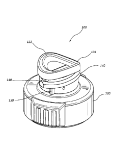
[0028] Referring now to Figure 3, a Luer access device 100 in accordance
to a
representative embodiment of the present invention is shown. Luer access
device 100 may
comprise any general structure or design that is presently known in the art.
For example, in
some instances Luer access device 100 comprises cap structure as shown in
Figure 3A. Luer
access device 100 may alternatively comprise a male Luer device, as shown in
cross-section
in Figure 3B. Luer access device 100 may further comprise an access port
structure that is
part of an intravenous connector.
[0029] Luer access device 100 comprises a body 120 made from a rigid or
semi-rigid
material having an opening 134 into which is seated a soft septum 122. Body
120 further
6
CA 02927992 2016-04-19
WO 2015/065700 PCT/US2014/060504
comprises a set of threads 140 that is positioned on the outer surface of body
120 and in
proximity to opening 134. Threads 140 are provided to facilitate a threaded
connection
between Luer access device 100 and a separate device 26, such as a syringe, a
Luer adapter, a
cap, or a section of intravenous tubing. In some instance, threads 140
comprises a plurality
of partial threads that occupy a portion of the outer surface of body 120,
wherein the partial
threads each have a thread length that is less than the circumference of the
outer surface on
which the threads are positioned.
[0030] Luer access device 100 further comprises a retention feature 150
that is
positioned on body 120 adjacent the set of threads 140. In general, retention
feature 150 is
positioned on body 120 such that retention feature 150 will contact a set of
complementary
threads on the separate device 26 when the separate device 26 is threadedly
coupled to Luer
access device 100 via threads 140. Accordingly, the specific location of
retention feature 150
may vary and still accomplish its intended purpose.
[0031] For example, in some instances retention feature 150 is positioned
below
thread 140 at a position near the middle or end of the thread, as shown in
Figures 3A and 3B.
As thus configured, the complementary threads of separate device 26 are able
to engage
threads 140 prior to contacting retention feature 150. As separate device 26
is further
threaded onto threads 140, the complementary threads of separate device 26
contact retention
feature 150 thereby providing a tactile sensation to the user of a tightening
connection
between the two components. Contact between the complementary set of threads
and
retention feature 150 further provided increased friction between the threaded
components,
thereby overcoming the "spring back" effect caused by soft septum 122.
[0032] Retention feature 150 may comprise any shape, configuration,
texture or other
feature that is compatible with the teachings of the present invention. In
some instances,
retention feature 150 comprises a protrusion that provides an obstacle in the
pathway for a set
of complementary threads that is intended to threadedly engage threads 140.
[0033] For example, retention feature 150 may be positioned in proximity
to threads
140 so as to be in the pathway of a set of complementary threads of a separate
extravascular
device. As separate device 26 is initially threaded onto threads 140 of Luer
access device
100, a probe 138 portion of separate device 26 pierces septum 122, as shown in
Figure 3C.
In some instances, as probe 138 is advanced through septum 122, complementary
threads 36
do not immediately make contact with retention feature 150. Rather, threads
140 and
complementary threads 36 are permitted to freely and fluidly engage. However,
upon further
7
CA 02927992 2016-04-19
WO 2015/065700 PCT/US2014/060504
engagement between complementary threads 36 and threads 140, complementary
threads 36
contact retention feature 150 as separate device 26 and Luer access device 100
near complete,
threaded engagement, as shown in Figure 3D.
[0034] The contact and interaction between complementary threads 36 and
retention
feature 150 provides a change in the mechanics of the threaded connection. In
some
instances, this change requires increased rotational torque by the user to
complete the
threaded connection between the two components. In other instances, this
change further
provides increased friction between the two components, which can be felt by
the user as the
connection is tightened. Accordingly, retention feature 150 overcomes the
"spring back"
effect of soft septum 122, improving security of the connection while
simultaneously
provided the user with a desirable tactile feedback that confirms tightening
of the connection.
[0035] In some instances, the complementary threads of separate device 26
comprises
a compliant material that is temporarily or permanently deformed when the
complementary
threads of the device 26 contact retention feature 150, as shown in Figure 3E.
The contact
between the complementary threads and retention device 150 may temporarily or
permanently misshape the inner diameter of separate device 26, or the shape of
complementary threads, thereby increasing the rotational force required to
continue coupling
separate device 26 and Luer access device 100.
[0036] Conversely, in some instances retention feature 150 comprises a
compliant
material that is temporarily or permanently deformed when the noncompliant
complementary
threads of device 26 contact retention feature 150, as shown in Figure 3F. The
complementary threads of device 26 cut into retention feature 150, thereby
increasing friction
between the two components.
[0037] Further still, in some instances body 120 comprises a compliant
material that
is temporarily deformed when contact is made between separate device 26 and
retention
feature 150, as shown in Figure 3G. For example, in some instances a
noncompliant interface
between the complementary threads 36 and retention feature 150 displaces or
deflects
complementary threads 36 outwardly, thereby increasing the rotational torque
required to
complete the threaded connection between Luer access device 100 and separate
device 26.
[0038] Referring now to Figures 4A-4C, Luer access device 100 may further
comprise a tapered retention feature 250. In some instances, Luer access
device 100
comprises a single tapered retention feature 250 that is positioned beneath a
set of threads
140 of body 120, as shown in Figure 4A and 4B. In other embodiments, Luer
access device
8
CA 02927992 2016-04-19
WO 2015/065700 PCT/US2014/060504
100 comprises one or more tapered retention features 250 that are interposedly
positioned
between an upper thread 140a and a lower thread 140b on body 120, as shown in
Figure 4C.
Retention feature 250 tapers inwardly from upper thread 140a to lower thread
140b, such that
retention feature 250 comprises an upper thickness that tapers to a lower
thickness, wherein
the lower thickness is less than the upper thickness.
[0039] Referring now to Figures 5A and 5B, various cross-section views
are provided
which demonstrate the interaction between complementary threads 36 of separate
device 26
and tapered retention feature 250. As separate device 26 is threadedly coupled
to Luer access
device 100, the underside of complementary threads 36 is initially supported
by a top surface
of threads 140, as shown in Figure 5A. Upon further coupling or threading of
the devices,
contact is made between the terminal end 37 of separate device 26 and body 120
of Luer
access device 100, thereby preventing further insertion of probe 138 through
septum 122, as
shown in Figure 5B. In at least some embodiments, contact between
complementary threads
36 and tapered retention feature 250 occurs at or before the initiation of
contact between
terminal end 37 and body 120.
[0040] Upon further rotation of separate device 26, complementary threads
36 are
rotated with respect to the fixed position of body 120 and threads 140. The
pitch of
complementary threads 36 causes the rotating complementary threads 36 to
travel upwardly
across retention feature 250, such that a top surface of complementary threads
36 contacts a
bottom surface of upper threads 140a. As complementary threads 36 travels
across retention
feature 250, the outward taper of retention feature 250 increases resistance
between
complementary threads 36 and retention feature 250. This increased resistance
provides a
desired tactile sensation to the user which indicates that the connection
between the devices is
progressively tightening. When the top surface of complementary threads 36 is
fully seated
against the bottom surface of threads 140, and terminal end 37 is contacting
body 120, the
connection between the devices 100 and 26 is complete and the user is no
longer able to
further rotate and/or tighten the connection. The interaction between
complementary threads
36 and retention device 250 maintains the tightened connection, thereby
preventing any
"spring back" effect.
[0041] The present invention may comprise any number of retention
features, having
any variety of size, shape and features in harmony with the teachings herein.
For example,
with reference to Figures 6A-6C, some implementations of the present invention
comprise a
retention feature 350 comprising an asymmetric bump having various axial ramps
to assist in
9
CA 02927992 2016-04-19
WO 2015/065700 PCT/US2014/060504
tightening and loosening the connection between Luer access device 100 and
separate device
26.
[0042] In some instances, retention feature 350 comprises a forward
ramped surface
352 having a shallow, inclined pitch. The force required to pass complementary
threads 36
over retention feature 350 increases gradually as complementary threads 36
travel over the
inclined ramped surface 352. Retention feature 350 further comprises rearward
ramped
surface 354 which is opposite forward ramped surface 352 and includes a steep,
declined
pitch.
[0043] In some instances, complementary threads 36 comprise a compliant
material
that temporarily deforms when contacted by retention feature 350. As such,
when threadedly
coupling complementary threads 36 to threads 140, a portion of complementary
threads 36 in
contact with retention feature 350 gradually and temporarily deforms as the
threads 36 travel
up forward ramped surface 352 and over the apex 356 of retention feature 350.
As the
portion of complementary threads 36 passes over apex 356 and past rearward
ramped surface
354, the threads 36 are restored to their original form. Thus, the sections of
complementary
threads 36 not in contact with retention feature 350 are undeformed, while
those sections of
complementary threads 36 in contact with retention feature 350 are deformed,
as shown in
Figure 6C.
[0044] The interface between complementary threads 36 and the steeper
pitch of
rearward ramped surface 354 requires increased torque for disengaging or
unthreading
complementary threads 36 from threads 140, as compared to the torque required
to threadedly
engage threads 36 and 140 based on the shallower pitch of forward ramped
surface 354. This
feature prevents unintentional disengagement of separate device 26 from Luer
access device
100. Further, the steeper pitch and shorter length of rearward ramped surface
354 allows
quick disengagement of complementary threads 36 from retention feature 350
once the
required torque has been applied and the interface between complementary
threads 36 and
rearward ramped surface 354 has been released.
[0045] In some instances, Luer access device 100 further comprises a
retention
feature 450 having an asymmetrical wide bump 456 comprising an axial taper,
wherein the
wide bump 456 further comprises a shallow forward ramp 452 and a steep
rearward ramp
454, as shown in Figures 7A-7C. Forward and rearward ramps 452 and 454 provide
benefits
similar to those discussed in connection with retention feature 350, above.
Wide bump 456 is
equivalent to apex 356 of retention feature 350, however the increased width
of wide bump
CA 02927992 2016-04-19
WO 2015/065700 PCT/US2014/060504
456 increases the interface between retention feature 450 complementary
threads 36. As
such, the period of resistance between Luer access device 100 and separate
device 26 is
increased. The increased width of wide bump 456 further increases the length
or amount of
complementary threads 36 that are deformed by retention feature 450, thereby
requiring
additional torque to threadedly engage and/or disengage the interconnected
devices.
[0046] Wide bump 456 further comprises an axial taper, similar to the
taper of
retention feature 250, shown and discussed above in connection with Figures 4A-
5B. Thus,
as separate device 26 is threaded onto Luer access device 100, complementary
threads 36
travel upwardly on the axial taper of wide bump 456, thereby increasing the
resistance
between complementary threads 36 and retention feature 450. Complementary
threads 36 are
maximally engaged with threads 140 when an upper thread surface of
complementary threads
36 forms an interface with a lower thread surface of threads 140, thereby
preventing further
rotation of separate device 26. In this position, complementary threads 140
are positioned on
wide bump 456 at the maximum width of the axial taper, thereby maximizing the
interference
between retention feature 450 and complementary threads 36.
[0047] Referring now to Figures 8A-8C, some embodiments of the instant
invention
further include a retention feature 550 comprising a one-way barb. In some
embodiments,
retention feature 550 comprises a flexible, resilient material and is
positioned in the pathway
of complementary threads 36, such that complementary threads 36 contact and
temporarily
displace retention feature 550, as shown in Figure 8C. In some embodiments,
retention
feature 550 comprises a wide base and a narrower tip, such that the shear
strength of retention
feature 550 is less at the tip and greater at the base. Thus, less shear force
is required to
displace the tip of retention feature 550 than is required to displace the
base. As such, the
user is provided with a tactile sensation of a gradually tightening
connection. In some
instances, retention feature 550 comprises tapered sidewalls, such that the
shear strength of
retention feature 550 progresses linearly from the feature's tip to the base.
In other instances,
retention feature 550 comprises sidewalls having a configuration to achieve a
non-linear
progression of shear strength from the tip to the base.
[0048] The resilient nature of retention feature 550 applies an outward
force on
complementary threads 36 when displaced. This outward force provides a tactile
sensation to
the user which indicates that the threaded connection is tightening. The
outward force further
increases the torque required to continue advancing the threaded connection.
Once fully
engaged, the outward force prevents unintentional disengagement of the
threaded devices.
11
CA 02927992 2016-04-19
WO 2015/065700 PCT/US2014/060504
[0049] When unthreading the devices, the outward force applied by
retention feature
550 requires increased torque to overcome the frictional force between
complementary
threads 36 and retention feature 550. The frictional force between
complementary threads 36
and retention feature 550 gradually decreases as the devices are unthreaded
due to the tapered
configuration of complementary threads 36 and the resilient nature of
retention feature 550.
At the point in which complementary thread 36 no longer contacts retention
feature 550, all
frictional force between threads 36 and feature 550 ceases and the amount of
torque required
to unthread the devices decreases.
[0050] Referring now to Figure 9, in some embodiments a retention feature
650 is
provided as part of threads 140. In this configuration, retention feature 650
interacts with the
surface of separate device 26 that is interposed between, or adjacent to
complementary
threads 36, as opposed to directly interacting with complementary threads 36.
For example,
retention feature 650 may be designed to engage a major diameter of
complementary threads
36, wherein the previous retention feature embodiments are configured to
engage the minor
diameter of complementary threads 36.
[0051] Retention feature 650 may comprise any of the features or elements
of the
previously discussed retention features. For example, in some instances
retention feature 650
comprises a forward ramped surface 652 and a rearward ramped surface 654.
Retention
feature 650 may further comprise a wide bump surface. In some instances, a
Luer access
device is provided which comprises two or more retention features, wherein a
first retention
feature is configured to directly interact with a set of complementary
threads, and a second
retention feature is configured to interact with a surface of a separate
device that is interposed
between, or adjacent to the complementary threads.
[0052] In some instances, Luer access device 100 includes a retention
feature 750 that
comprises a portion of a separate thread 140a. Thus, a gap 141 is provided
between threads
140 and separate thread 140a. Retention feature 750 may include any feature or
combination
of features discussed above in connection with any of the other retention
features. In some
instances, retention feature 750 comprises wide bump 756 that is tapered
radially from the
forward ramped surface 752 to the rearward ramped surface 754. Thus, the
frictional force
between retention feature 750 and the major diameter of complementary threads
36 increases
gradually as contact between wide bump 756 and complementary threads is
advances.
[0053] The present invention may be embodied in other specific forms
without
departing from its structures, methods, or other essential characteristics as
broadly described
12
CA 02927992 2016-04-19
WO 2015/065700 PCT/US2014/060504
herein and claimed hereinafter. Thus, the described embodiments are to be
considered in all
respects only as illustrative, and not restrictive. The scope of the invention
is, therefore,
indicated by the appended claims, rather than by the foregoing description.
All changes that
come within the meaning and range of equivalency of the claims are to be
embraced within
their scope.
13