Note: Descriptions are shown in the official language in which they were submitted.
CA 02928046 2016-04-19
WO 2015/061911
PCT/CA2014/051051
SYSTEM AND METHOD FOR HOT STAMPING OF COMPONENTS
FIELD OF THE INVENTION
[0001] The invention relates generally to a system and method for hot stamping
components.
In particular, the system includes a station for the provision of blanks, a
furnace station for
heating the blanks to the deformation temperature, and a press having a tool
that is designed
for press hardening / hot stamping technology.
BACKGROUND
[0002] Steel continues to be the material of choice when it comes to modern
and cost-
effective vehicle bodies. In terms of material, new steels that combine high
strength with good
formability have been developed in response to the demands of the automotive
industry for
lightweight construction materials. In particular, the multiphase steels are
used extensively in
hot stamping processes in which a steel blank is heated into the zone of full
austenitization
(typically 920 C). The heated blank is subsequently inserted into the forming
tool while still
hot, and is rapidly cooled during the pressing operation. From a relatively
soft, ferritic-
pearlitic initial structure, hard martensite with strengths of at least about
1500 MPa is
obtained. The forming behaviour is controlled by means of the boron content
and the strength
is controlled by means of the carbon content. Typically, a boron-alloyed steel
with 0.24%
carbon is employed.
[0003] Advantages of the press hardening method include the low forming
resistance and the
better formability of steel at this temperature, as well as the high strength
and good
dimensional stability of the obtained component. In general, the use of hot
stamping methods
and new steel materials results in high-strength but low-weight vehicle
bodies.
[0004] Due to the increasing use of hot stamping technology in the automotive
industry, the
press-hardening machinery is becoming faster. Machines that achieve five
strokes per minute
have been in use for some time already, and newer machines that achieve seven
strokes per
minute are known. As a result of the reduced cycle length, the efficiency of
the hot stamping
method is increased. However, the heating of the supplied blanks via heating
furnaces has
hitherto been the limiting factor. Since the blanks have to be heated to a
processing
temperature of over 900 C, heating furnaces which are configured as
continuous furnaces are
used. Over a 30 m length of such a continuous furnace, the blank is heated by
30 C per
1
CA 02928046 2016-04-19
WO 2015/061911
PCT/CA2014/051051
metre. Accordingly, the pass-through speed of the blanks and the length of the
heating
furnaces limits the cycle length of the hot stamping system.
[0005] It would be beneficial to provide a system and method that improves
and/or
overcomes at least some of the above-mentioned disadvantages.
SUMMARY OF EMBODIMENTS OF THE INVENTION
[0006] It is an object of the invention to provide a hot stamping system,
which is optimized
for processes with higher cycle durations. That is to say, the cycle rate is
increased such that
more strokes per minute are achievable.
[0007] According to an aspect of at least one embodiment of the invention,
provided is a
system for hot stamping of components, comprising: a station for providing
steel blanks; a
tempering container for storing the steel blanks and for pre-heating the steel
blanks to a pre-
heating temperature; a furnace station for receiving the pre-heated steel
blanks from the
tempering container and for further heating the steel blanks to a
predetermined deformation
temperature; and a press having a tool that is designed for hot stamping
technology, the press
for receiving the heated steel blanks from the furnace station and for hot
stamping the
components.
[0008] Through the use of a tempering container, a part of the heating process
is performed
prior to introducing the blanks into the furnace station. As a result, the
furnace station is
shortened and the pass-through process can thereby be adapted to the faster
cycle rates of the
presses.
[0009] In at least one embodiment the blanks are heated in the tempering
container to a
temperature of at least 100 C. As a result, the furnace station can be
shortened by several
metres, since the blanks are introduced into the furnace station already with
a starting
temperature higher than the ambient atmosphere.
[0010] In at least one embodiment the furnace station is a continuous furnace
and is directly
connected to the tempering container.
[0011] The direct connection between the tempering container and the
continuous furnace
has the advantage that the blanks do not cool down in the course of the
process, e.g. during
transfer between the tempering container and the continuous furnace.
2
CA 02928046 2016-04-19
WO 2015/061911
PCT/CA2014/051051
[0012] In at least one embodiment the system is designed such that the
continuous furnace
for the system, given a target temperature above 900 C, is shortened by at
least 5 m.
[0013] Through the shortening of the length of the continuous furnace, the
time needed for
the heating of the blanks is shortened and the blanks can be removed from the
press at a faster
rate.
[0014] In at least one embodiment the tempering container is heated with the
waste gas of
the continuous furnace. Through the return of the waste heat of the continuous
furnace into
the tempering container, an advantageous solution from an energy viewpoint is
obtained. The
need for higher power levels, as would otherwise be required with a shortened
furnace to
maintain the same target temperature, is avoided. On the contrary, the use of
energy is
reduced in that the waste heat is passed into the tempering container and is
used there to
preheat the blanks.
[0015] It is additionally of advantage that the method for the hot stamping of
components
comprises the following steps:
= provision of blanks,
= introduction of the blanks into a tempering container
= heating of the blanks in the tempering container
= introduction of the preheated blanks into a continuous furnace
= pressing in a press hardening / hot stamping tool.
[0016] Advantageously, if the blanks are heated to a higher temperature in the
tempering
container, then the length of the continuous furnace may be decreased. The
higher the
temperature in the tempering container, the shorter the minimum length of the
continuous
furnace.
[0017] It is additionally of advantage that the waste heat of the continuous
furnace is utilized
to heat the tempering container in order to obtain an optimal utilization of
the energy and, at
the same time, to shorten the cycle time.
BREIF DESCRIPTION OF THE DRAWINGS
[0018] The invention will now be described by way of example only, and with
reference to
the attached drawing. It should be understood that the drawing is not
necessarily to scale. In
3
CA 02928046 2016-04-19
WO 2015/061911
PCT/CA2014/051051
certain instances, details that are not necessary for an understanding of the
disclosure or that
render other details difficult to perceive have been omitted.
[0019] Fig. 1 is a simplified diagram showing a system according to an
embodiment of the
invention.
DETAILED DESCRIPTION OF THE DRAWINGS
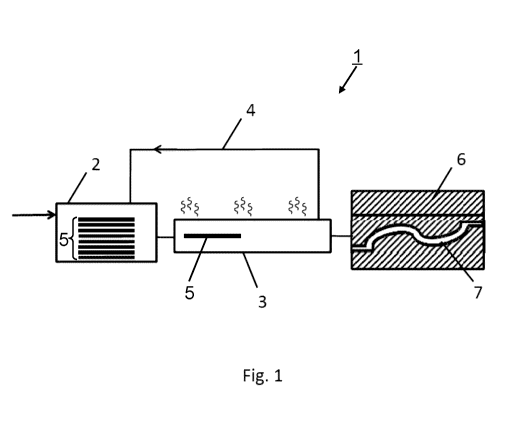
[0020] Referring to Fig. 1, a hot stamping system 1 includes a tempering
container 2, which
is connected to a furnace station 3. The furnace station 3 is in turn
connected to a press 6. The
furnace station 3 supplies heat into the tempering container 2 via a waste gas
return line 4. In
the tempering container, blanks 5 are represented schematically. The blanks 5
are prepared by
a blank-providing station, which is represented in the drawing only
schematically as an arrow
on the left-hand side, and are delivered to the tempering container 2. The
blanks can here be
simple portions of steel bands supplied on rolls, or can exist in a form
already pre-trimmed by
a trimming station. The blanks 5 are inserted into the tempering container 2.
Present in the
tempering container 2 is an apparatus in which the blanks can be stored at a
distance apart, so
that the individual blanks can be easily removed again. In the present example
the tempering
container is designed such that the residence time of the blanks in the
tempering container is
sufficient to preheat them to the preheat temperature of over 100 C, most
advantageously to
180 C. Optionally, the blanks are preheated in the tempering container to
even higher
temperatures, if such higher temperatures can be obtained via the waste gas
return line.
[0021] According to the "first in - first out" principle, the blank that has
resided for the
longest time in the tempering container 2 is removed first, followed by the
blank that has
resided for the second longest time in the tempering container 2, and so on.
It is thereby
ensured that the removed blank is already at the preheat temperature. The
preheated blank 5 is
introduced into the furnace via a direct connection of the tempering container
2 to the furnace
3. In the furnace 3, the blank 5 passes through the entire furnace length
between the tempering
container 2 and the press 6. At the end of the furnace 3, the blank 5 is
removed and
immediately inserted into the pressing tool 7 of the press 6.
[0022] The design of the tempering container 2 for blanks 5 can be shown on
the basis of an
example. An exemplary continuous furnace in the furnace station 3 has a length
of 30 m and
obtains a predetermined exemplary deformation temperature of 920 C. The
downstream
press has currently five strokes per minute. Should it be desired to operate
the machine at 7
4
CA 02928046 2016-04-19
WO 2015/061911
PCT/CA2014/051051
strokes per minute, this means an increase of about 20% in the cycle
frequency. It therefore
follows that the blanks 5 must arrive at the press 20 % quicker out of the
furnace station 3,
and the continuous furnace must therefore be shortened by about 6 m. With a
heating rate of
30 C per 1 m of furnace length, this means that the tempering container must
be set to 180 C
in order to feed a continuous furnace length of about 24 m.
5
CA 02928046 2016-04-19
WO 2015/061911
PCT/CA2014/051051
Reference symbols
1 hot stamping system
2 tempering container
3 furnace station
4 waste gas return line
5 blank
6 press
7 pressing tool
6