Language selection

Search

Patent 2928081 Summary

Third-party information liability

Some of the information on this Web page has been provided by external sources. The Government of Canada is not responsible for the accuracy, reliability or currency of the information supplied by external sources. Users wishing to rely upon this information should consult directly with the source of the information. Content provided by external sources is not subject to official languages, privacy and accessibility requirements.

Claims and Abstract availability

Any discrepancies in the text and image of the Claims and Abstract are due to differing posting times. Text of the Claims and Abstract are posted:

  • At the time the application is open to public inspection;
  • At the time of issue of the patent (grant).
(12) Patent: (11) CA 2928081
(54) English Title: CAM ASSEMBLY FOR USE WITH POLE CLIMBING FALL RESTRICTION DEVICE
(54) French Title: MECANISME DE CAME DESTINE A UN DISPOSITIF DE RESTRICTION DE CHUTE LORS DE L'ESCALADE DE POTEAU
Status: Granted
Bibliographic Data
(51) International Patent Classification (IPC):
  • A63B 27/00 (2006.01)
(72) Inventors :
  • TRUESDELL, KEVIN W. (United States of America)
  • BATTY, TIMOTHY (United States of America)
  • RULLO, JAMES J. (United States of America)
  • CANFIELD, DEFOREST C. (United States of America)
(73) Owners :
  • BUCKINGHAM MANUFACTURING COMPANY, INC. (United States of America)
(71) Applicants :
  • BUCKINGHAM MANUFACTURING COMPANY, INC. (United States of America)
(74) Agent: MOFFAT & CO.
(74) Associate agent:
(45) Issued: 2018-09-18
(22) Filed Date: 2016-04-25
(41) Open to Public Inspection: 2016-10-24
Examination requested: 2016-04-25
Availability of licence: N/A
(25) Language of filing: English

Patent Cooperation Treaty (PCT): No

(30) Application Priority Data:
Application No. Country/Territory Date
62/152,085 United States of America 2015-04-24

Abstracts

English Abstract

In a pole climbing fall prevention assembly having a pole strap, lanyard, and cam assembly that permits adjustment of the pole strap, a lever is attached to the sidewall of a cam assembly to ease the task of a climber needing to adjust the pole strap. A second lever can be attached to the second sidewall of the cam assembly to provide easier access to the lever regardless of the orientation of the cam assembly relative to the climber.


French Abstract

Un ensemble de prévention des chutes lors de lescalade dun mât comporte une sangle de mât, une longe et un ensemble came qui permet dajuster la sangle de mât. Un levier est fixé à la paroi latérale dun ensemble de came pour faciliter la tâche à un grimpeur ayant besoin dajuster la sangle de mât. Un second levier peut être fixé à la seconde paroi latérale de lensemble came pour fournir un accès plus facile au levier, peu importe lorientation de lensemble came par rapport au grimpeur.

Claims

Note: Claims are shown in the official language in which they were submitted.


WHAT IS CLAIMED IS:

1) A cam assembly for use with a pole climbing fall restriction device that
comprises
a pole strap and a lanyard, said cam assembly comprising:
a) a body having a base and opposing, first and second sidewalls;
b) a cam pivotally connected to said body;
c) a spring attached to said cam and producing a bias force thereto relative
to said
body; and
d) a first lever attached to said first sidewall, wherein said first lever is
separate from
said cam and is configured to assist in overcoming said spring bias force;
e) wherein said first lever is attached to an outside surface of said first
sidewall.
2) The cam assembly according to claim 1, further comprising a second lever
attached
to said second sidewall.
3) The cam assembly according to claim 2, further comprising first and
second non-
slip coverings positioned over said first and second levers, respectively.
4) The cam assembly according to claim 3, wherein each of said first and
second non-
slip coverings are brightly colored to provide a source of visual distinction.
5) The cam assembly according to any one of claims 2 to 4, further
comprising a
directional indicator applied to at least one of said first and second levers.
6) The cam assembly according to claim 1 or 2, further comprising a first
non-slip
covering positioned over said first lever.
7) The cam assembly according to claim 6, wherein said first non-slip
covering is
brightly colored to provide a source of visual distinction.

7


8) The cam assembly according to claim 1 or 2, further comprising a
directional
indicator applied to said first lever.
9) A pole fall restriction assembly, comprising:
a) an elongated pole strap; and
b) a cam assembly attached to said elongated pole strap and comprising:
i) a body having a base and opposing, first and second sidewalls;
ii) a cam pivotally connected to said body;
iii) a spring attached to said cam and producing a bias force thereto relative
to said
body; and
iv) a first lever attached to said first sidewall, wherein said first lever is
separate
from said cam and is configured to assist in overcoming said spring bias
force;
v) wherein said first lever is attached to an outside surface of said first
sidewall.
10) The pole fall restriction assembly of claim 9, further comprising an
elongated
lanyard.
11) The pole fall restriction assembly of claim 10, wherein said cam
assembly further
comprises an eyelet formed through said cam.
12) The pole fall restriction assembly of claim 11, further comprising a
connector
interconnecting said cam assembly to said elongated lanyard.
13) The pole fall restriction assembly of claim 12, wherein said connector
passes
through said eyelet.
14) The pole fall restriction assembly of any one of claims 9 to 13,
wherein said cam
assembly further comprises a second lever attached to said second sidewall.

8


15) The pole fall restriction assembly of claim 14, further comprising
first and second
non-slip coverings positioned over said first and second levers, respectively.
16) The pole fall restriction assembly of claim 15, wherein each of said
first and second
non-slip coverings are brightly colored to provide a source of visual
distinction.
17) The pole fall restriction assembly of any one of claims 14 to 16,
further comprising
a directional indicator applied to at least one of said first and second
levers.
18) The pole fall restriction assembly of any one of claims 9 to 13,
further comprising a
first non-slip covering positioned over said first lever.
19) The pole fall restriction assembly of claim 18, wherein said first non-
slip covering
is brightly colored to provide a source of visual distinction.
20) The pole fall restriction assembly of any one of claims 9 to 19,
further comprising a
directional indicator applied to said first lever.

9

Description

Note: Descriptions are shown in the official language in which they were submitted.


CA 02928081 2016-04-25
CAM ASSEMBLY FOR USE WITH POLE CLIMBING
FALL RESTRICTION DEVICE
BACKGROUND
1. FIELD OF INVENTION
[0001] The present invention relates generally to pole climbing
equipment,
and more particular to assemblies that assist in preventing a person from
falling while
ascending or descending a pole.
2. BACKGROUND OF ART
[0002] Pole fall restriction devices are well known in the art. The
assemblies typically comprise a pole strap that is adapted to wrap around the
pole, a front
strap or lanyard that connects to both the pole strap and the user's body
harness and wraps
around the front of the pole nearest the user, and adjustment hardware for
adjusting the
effective length of the pole strap and lanyard. When a user begins ascending
or
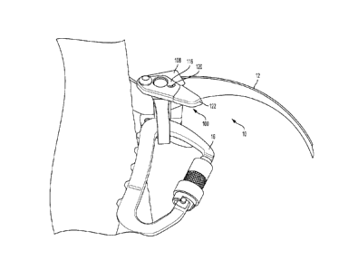
descending a pole, he or she will grab a hold of the pole strap near one end,
while making
any necessary adjustments to the effective length of the straps with the other
hand. When
actually ascending or descending, the user will hold the ends of the pole
strap and move it
up or down while hitchhiking up or down the pole.
[0003] To adjust the length of the pole strap wrapped around the
pole, the
climber manipulates a spring-biased cam. When in its neutral condition, the
cam securely
grips and retains the webbing from which the pole strap is composed. To alter
the
effective length of the pole strap, the climber must manually overcome the
spring-bias of
the cam such that it no longer engages the webbing, thereby permitting the
webbing to
1

CA 2928081 2018-02-12
slide freely through the cam. Once the desired alteration to the effective
length of the
webbing is achieved, the climber can release the cam thus permitting the bias
of the spring
to forcibly close the cam into securely engaged relation with the webbing.
100041 While the spring biased cam is an effective tool for adjusting the
pole strap, its manipulation by a climber is not easy. The climber is
suspended above the
ground, supported only by a harness and the fall prevention assembly. While
having to
hold the pole strap with one hand, the other hand is then used to overcome the
spring bias
and then slide the pole strap to the desired position. The simultaneous
manipulation of
several items, while suspended and balancing oneself relative to a pole
requires ample
training and skill.
3. OBJECTS AND ADVANTAGES
[0005] It is therefore a principal object and advantage of the present
invention to provide a cam assembly that includes levers to assist the climber
in
overcoming the spring bias and adjust the pole strap.
[0006] Other objects and advantages will in part be obvious and in part
appear hereinafter.
SUMMARY OF THE INVENTION
[0007] In accordance with the foregoing object and advantage, one aspect
of the present invention provides a cam assembly for use with a pole climbing
fall
restriction device that comprises a pole strap and a lanyard, the cam assembly
comprising:
a body having a base and opposing, first and second sidewalls; a cam pivotally
connected
to the body; a spring attached to the cam and producing a bias force thereto
relative to the
2

CA 2928081 2018-02-12
body; and a first lever attached to the first sidewall, wherein the first
lever is separate from
the cam and is configured to assist in overcoming the spring bias force;
wherein the first
lever is attached to an outside surface of the first sidewall.
[0008] In another aspect of the invention a second lever is attached to the
other of the opposing sidewalls.
[0009] In another aspect of the invention, the first and second levers are
coated or covered with a non-slip material.
[0010] In another aspect of the invention, the non-slip material is
preferably
brightly colored so as to serve as a source of visual distinction making it
easier to see and
grab.
[0011] In another aspect of the invention directional indicators are
applied
to/printed upon either or both of the first and second levers.
[0012] In yet another aspect, there is provided a pole fall restriction
assembly, comprising: an elongated pole strap; and a cam assembly attached to
the
elongated pole strap and comprising: a body having a base and opposing, first
and second
sidewalls; a cam pivotally connected to the body; a spring attached to the cam
and
producing a bias force thereto relative to the body; and a first lever
attached to the first
sidewall, wherein the first lever is separate from the cam and is configured
to assist in
overcoming the spring bias force; wherein the first lever is attached to an
outside surface of
the first sidewall.
3

BRIEF DESCRIPTION OF THE DRAWINGS
[0013] The present invention will be more fully understood and
appreciated
by reading the following Detailed Description in conjunction with the
accompanying
drawings, in which:
[0014] Figure 1 is close-up perspective view of an embodiment of the
present invention in use with a pole strap and lanyard connecting carabineer.
[0015] Figure 2 is a top plan view of an embodiment of the
present
invention assembled with a pole strap and lanyard connecting carabineer.
[0016] Figure 3 is a top plan view of an embodiment of the
present
invention assembled on a pole strap.
[0017] Figure 4 is a front elevation view of an embodiment of
the present
invention assembled on a pole strap.
[0018] Figure 5 is another top plan view of an embodiment of
the present
invention assembled on a pole strap.
[0019] Figure 6 is a perspective view of a spring and cam assembly;
[0020] Figure 7 is a perspective view of a spring and cam
assembled with
the body of the cam assembly.
DETAILED DESCRIPTION
[0021] Referring now to the drawings, in which like reference numerals
refer to like parts throughout, there is seen in Figure 1 a pole climbing fall
prevention
assembly designated generally by reference numeral 10, comprising a pole strap
12, a
lanyard 14 (see Figure 2), a cam assembly, designated generally by reference
numeral 100,
4
CA 2928081 2017-09-28

through which pole strap 12 passes and is connected, and a connector (e.g.,
carabincer) 16
interconnecting cam assembly 100 to lanyard 14. Pole strap 12 is composed of a
length of
webbing (made of nylon, leather or other pliable but durable material).
[0022] Cam assembly 100 will be referred to hereinafter as a
"web grab" as
that is indicative of the function it serves (i.e., grabbing a web of
material). Web grab 100
comprises a cam 102 pivotally connected to a base 106, and a pair of opposed
sidewalls
108/110 formed on opposite sides of base 106. Cam 102 connects to base 106 by
a spring
112 that is coiled within cam 102 and bolt 114 that passes through sidewall
108 and spring
112 and serves as the pivot axis for cam 102 relative to housing 104. Spring
112 naturally
biases cam 102 into engaged relation with base 106; in order to separate cam
102 from
base 106, thereby creating a space through which pole strap 12 can pass, one
must
manually overcome the spring force and pivot cam 102 away from base 106. Once
the
manually applied force is removed. spring 112 will bias cam 102 back into
engaged
relation with base 106 - or pole strap 12 (assuming it is passed between cam
102 and base
106). When pole strap 12 is passed between cam 102 and base 106, cam 102 will
secure
the positioning of pole strap 12 in place until the bias of spring 112 is
manually overcome,
thereby permitting the pole strap to be moved/adjusted relative to web grab
100.
[0023] Web grab 100 is connected to lanyard 14 by connector 16.
Connector 16 is removably attached to cam 102 by passing the leg of connector
16 through
an eyelet 115 formed through cam 102. Connector 16 also includes an eye 18
through
which lanyard 14 passes. The weight of a climber to whom the lanyard 14 is
tethered
creates a pulling force that causes cam 102 to remain securely engaged with
pole strap 12.
To adjust pole strap 12 the climber must permit some slack to be formed in
lanyard 14.
5
CA 2928081 2017-09-28

[0024] To assist a climber with overcoming the spring bias, web
grab 100
further comprises a pair of levers 116/118 securely attached to sidewalls
108/110,
respectively, by bolts or other conventional fastening means. A directional
indicator 120 is
printed on levers 116/118 to assist the climber in immediately knowing which
way to
move the lever in order to overcome the spring bias and cause separation
between cam 102
and pole strap 12. Web grab 100 could be equipped with only a single lever
instead of
two, but providing the two levers permits either side of the web grab 100 to
be accessed
depending on the orientation of web grab 100 relative to the climber. Levers
116/118
extend outwardly away from web grab 100 to provide a moment arm that minimizes
the
amount of force needed to be applied to the lever in order to overcome the
spring bias. In
addition, a non-slip, brightly colored covering 122 is applied over the ends
of levers
116/118 to make it both more comfortable and easier for the climber to see and
use.
6
CA 2928081 2017-09-28

Representative Drawing
A single figure which represents the drawing illustrating the invention.
Administrative Status

For a clearer understanding of the status of the application/patent presented on this page, the site Disclaimer , as well as the definitions for Patent , Administrative Status , Maintenance Fee  and Payment History  should be consulted.

Administrative Status

Title Date
Forecasted Issue Date 2018-09-18
(22) Filed 2016-04-25
Examination Requested 2016-04-25
(41) Open to Public Inspection 2016-10-24
(45) Issued 2018-09-18

Abandonment History

There is no abandonment history.

Maintenance Fee

Last Payment of $277.00 was received on 2024-04-19


 Upcoming maintenance fee amounts

Description Date Amount
Next Payment if standard fee 2025-04-25 $277.00
Next Payment if small entity fee 2025-04-25 $100.00

Note : If the full payment has not been received on or before the date indicated, a further fee may be required which may be one of the following

  • the reinstatement fee;
  • the late payment fee; or
  • additional fee to reverse deemed expiry.

Patent fees are adjusted on the 1st of January every year. The amounts above are the current amounts if received by December 31 of the current year.
Please refer to the CIPO Patent Fees web page to see all current fee amounts.

Payment History

Fee Type Anniversary Year Due Date Amount Paid Paid Date
Request for Examination $800.00 2016-04-25
Application Fee $400.00 2016-04-25
Maintenance Fee - Application - New Act 2 2018-04-25 $100.00 2018-04-04
Final Fee $300.00 2018-08-07
Maintenance Fee - Patent - New Act 3 2019-04-25 $100.00 2019-04-22
Maintenance Fee - Patent - New Act 4 2020-04-27 $100.00 2020-04-17
Maintenance Fee - Patent - New Act 5 2021-04-26 $204.00 2021-04-16
Maintenance Fee - Patent - New Act 6 2022-04-25 $203.59 2022-04-15
Maintenance Fee - Patent - New Act 7 2023-04-25 $210.51 2023-04-21
Maintenance Fee - Patent - New Act 8 2024-04-25 $277.00 2024-04-19
Owners on Record

Note: Records showing the ownership history in alphabetical order.

Current Owners on Record
BUCKINGHAM MANUFACTURING COMPANY, INC.
Past Owners on Record
None
Past Owners that do not appear in the "Owners on Record" listing will appear in other documentation within the application.
Documents

To view selected files, please enter reCAPTCHA code :


To view images, click a link in the Document Description column. To download the documents, select one or more checkboxes in the first column and then click the "Download Selected in PDF format (Zip Archive)" or the "Download Selected as Single PDF" button.

List of published and non-published patent-specific documents on the CPD .

If you have any difficulty accessing content, you can call the Client Service Centre at 1-866-997-1936 or send them an e-mail at CIPO Client Service Centre.


Document
Description 
Date
(yyyy-mm-dd) 
Number of pages   Size of Image (KB) 
Abstract 2016-04-25 1 11
Description 2016-04-25 6 195
Drawings 2016-04-25 7 628
Claims 2016-04-25 3 75
Cover Page 2016-11-04 2 56
Representative Drawing 2017-01-18 1 16
Amendment 2017-09-28 21 591
Description 2017-09-28 6 188
Claims 2017-09-28 3 85
Drawings 2017-09-28 7 90
Examiner Requisition 2017-12-18 4 225
Amendment 2018-02-12 8 258
Description 2018-02-12 6 196
Claims 2018-02-12 3 89
Maintenance Fee Payment 2018-04-04 1 60
Final Fee 2018-08-07 1 44
Representative Drawing 2018-08-21 1 7
Cover Page 2018-08-21 1 34
New Application 2016-04-25 2 84
Examiner Requisition 2017-03-28 5 226