Note: Descriptions are shown in the official language in which they were submitted.
- 1
CORE LAYER HAVING WOOD ELEMENTS, IN PARTICULAR WOOD ELEMENTS
HAVING A CORRUGATED STRUCTURE
FIELD OF THE INVENTION
The present invention relates to a core layer which has wood elements of zig-
zag-
shaped form, preferably wood elements with an undulating structure, which core
layer is
suitable for the production of a multilayer composite or in a multilayer
composite,
preferably for the production of a lightweight panel, and to a multilayer
composite which
has the core layer. The invention also relates to methods for producing the
core layer
and the multilayer composite.
BACKGROUND OF THE INVENTION
It is known to use composite materials for the production of multilayer
composites, which
have relatively high mechanical stability in relation to their weight. Such
multilayer
composites are used for example in the form of lightweight panels.
CH 254025 relates to a multilayer composite which has two surface panels and a
core
layer in between, wherein the core layer has at least one layer of folded
veneer. The
veneer is folded at an angle relative to the fiber direction in the wood.
DE 42 01 201 relates to semifinished products or finished products composed of
wood,
said products being produced from plate-like areal elements. The plate-like
elements
may be of zig-zag-shaped form. They may be present in a random distribution
together
with areal elements, or may be superposed in the manner of scales.
DE 10 2008 022 806 relates to a lightweight panel with an undulating wood
veneer layer.
.. The undulations may be of zig-zag-shaped form.
CA 2928240 2018-05-31
- 2 -
BE 547 811 relates to a core layer composed of two wood elements of zig-zag-
shaped
form, which are arranged between two surface layers. The wood elements are
arranged
such that their edges preferably enclose an angle of 90 with one another.
DE 10 2008 022805 Al relates to an undulating veneer panel and to lightweight
panels
constructed therefrom. The undulating structure of the wood elements used may
be of
zig-zag shape, sinusoidal form and trapezoidal form. The wood elements are
stacked
one inside the other.
EP 1 923 209 relates to a lightweight composite panel with outer layers and a
central
layer, wherein the central layer is arranged at an angle with respect to the
plane of the
lightweight composite panel.
Said multilayer composites from the prior art have in common the fact that the
core layer
can have a broken-up structure. Under the action of a force perpendicular to
the surface
of the multilayer composite, said multilayer composite has a damping action,
because
the core layer can be at least partially compressed. A disadvantage of said
broken-up
core layers is that they can exhibit low homogeneity, which arises owing to
relatively
large cavities in the core layer. Then, in the case of fastening means, such
as for
example nails, furniture connectors or screws, being introduced, these may
strike
cavities in the broken-up core layers. This may result in limited stability of
the fastening
means in the multilayer composite. This in turn may have the effect that the
stability of
the multilayer composite on a support, for example on a wall, can be impaired
if said
multilayer composite is to be fastened to the wall by way of nails or screws.
Furthermore,
the production of core layers in large format necessitates correspondingly
large veneer
pieces of high quality.
OBJECT OF AN ASPECT OF THE INVENTION
It is an object of an aspect of the present invention to provide a core layer
and a
multilayer composite comprising the core layer, which multilayer composite
exhibits
improved stability with regard to fastening by way of nails, furniture
connectors or screws
or equivalent fastening means to a support, for example to a wall, and which
multilayer
composite makes it possible to realize an increased load-bearing capacity
while being of
the lowest possible weight.
CA 2928240 2018-05-31
- 3 -
SUMMARY OF THE INVENTION
Said object of an aspect is achieved according to the invention by way of a
core layer
.. which is suitable for a multilayer composite which has at least one surface
layer and one
core layer, wherein the surface layer is arranged so as to at least partially
cover the core
layer and be fixedly connected thereto, and by way of the multilayer composite
having
the core layer, wherein the core layer has wood elements, which have regions
which are
arranged in zig-zag-shaped fashion, as described herein.
In accordance with an aspect, there is provided a core layer, wherein the core
layer has
elements of zig-zag-shaped form composed of wood, which elements have plate-
like regions which are arranged in zig-zag-shaped fashion, wherein a zig
region of
an element with an adjoining zag region of the element of zig-zag-shaped form
form
a common edge between them, and wherein elements of zig-zag-shaped form are
arranged in the core layer such that two such edges of two elements of zig-zag-
shaped form, which edges may be the same as or different from one another,
cross
one another at a non-zero angle, wherein the two elements are fixedly
connected to
one another at the crossing point, wherein the wood elements in the core layer
have one or more of the following arrangements (a) to (d):
(a) the plate-like regions of the wood elements are planar surfaces, and the
edge
formed between the planar surfaces is a planar surface;
(b) the plate-like regions of the wood elements are surfaces of curved form,
and
the edge formed between the curved surfaces is a surface of curved form;
(c) the plate-like regions of the wood elements are surfaces of curved form,
and
the edge formed between the curved surfaces is rectilinear;
(d) the plate-like regions of the wood elements are surfaces of curved form,
and
the edge formed between the curved surfaces is a surface of planar form;
and wherein
(a) the elements composed of wood in the core layer are provided in a random
distribution; or
CA 2928240 2018-05-31
- 4 -
(3) the elements composed of wood in the core layer are arranged adjacent to
one
another and one above the other in random fashion; or
(y) the elements composed of wood in the core layer are arranged randomly, and
the edges cross one another at different angles;
wherein the wood elements of zig-zag-shaped form have fibers with a
preferential
direction, wherein the common edge or the common edges runs or run non-
parallel with
respect to the preferential direction.
The expressions used below in quotation marks are defined in the context of
the
invention.
BRIEF DESCRIPTION OF THE DRAWINGS
Figure 1 shows a longitudinal section through a first embodiment of a wood
element of a
multilayer composite according to the invention.
Figure 2 shows a longitudinal section through a second embodiment of a wood
element
of a multilayer composite according to the invention.
Figure 3 shows a longitudinal section through a third embodiment of a wood
element of a
multilayer composite according to the invention.
Figure 4 shows a longitudinal section through a fourth embodiment of a wood
element of
a multilayer composite according to the invention.
Figure 5 shows a longitudinal section through a fifth embodiment of a wood
element of a
multilayer composite according to the invention.
Figure 6 shows a longitudinal section through a sixth embodiment of a wood
element of a
multilayer composite according to the invention.
Figure 7 shows a longitudinal section through a seventh embodiment of a wood
element
of a multilayer composite according to the invention.
CA 2928240 2018-05-31
- 5 -
Figure 8 shows a longitudinal section through an eighth embodiment of a wood
element
of a multilayer composite according to the invention.
Figure 9 shows a longitudinal section through a ninth embodiment of a wood
element of
a multilayer composite according to the invention.
Figure 10 shows a longitudinal section through a tenth embodiment of a wood
element of
a multilayer composite according to the invention.
Figure 11 shows a longitudinal section through an eleventh embodiment of a
wood
element of a multilayer composite according to the invention.
Figure 12 shows a longitudinal section through a twelfth embodiment of a wood
element
of a multilayer composite according to the invention.
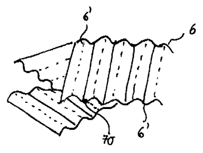
Figure 13 shows an arrangement of wood elements of undulating form in the core
layer
according to the invention of a further preferred embodiment of a multilayer
composite
according to the invention.
Figure 14 shows an arrangement of wood elements of undulating form from Figure
13 in
the core layer according to the invention of a further preferred embodiment of
a
multilayer composite according to the invention.
DETAILED DESCRIPTION OF THE INVENTION
First aspect of the invention
Core layer according to the invention having elements of zig-zag-shaped form
composed of wood
In a first aspect, the invention relates to a core layer, wherein the core
layer has
elements composed of wood, which elements have plate-like regions which are
arranged
in zig-zag-shaped fashion, wherein a zig region of an element with an
adjoining zag
region of the element form a common edge between them, in such a way that the
element is of zig-zag-shaped form, and wherein elements are arranged in the
core layer
CA 2928240 2018-05-31
- 6 -
such that two such edges of two elements, which edges may be the same as or
different
from one another, cross one another at a non-zero angle, wherein the two
elements are
fixedly connected to one another at the crossing point, as defined in claim 1.
In particular, the invention relates to a core layer which is suitable for a
multilayer
composite which has at least one surface layer and one core layer, wherein the
surface
layer is arranged so as to at least partially cover the core layer and be
fixedly connected
thereto, wherein the core layer has elements composed of wood, which elements
have
plate-like regions which are arranged in zig-zag-shaped fashion, wherein a zig
region of
an element with an adjoining zag region of the element form a common edge
between
them, in such a way that the element is of zig-zag-shaped form, and wherein
elements
are arranged in the core layer such that two such edges of two elements, which
edges
may be the same as or different from one another, cross one another at a non-
zero
angle, wherein the two elements are fixedly connected to one another at the
crossing
point.
The elements composed of wood are (a) situated in the core layer in a random
distribution. They may also be (13) arranged in the core layer adjacent to one
another and
one above the other in random fashion. The elements composed of wood may also
(y)
be arranged randomly in the core layer, and the edges may cross one another at
different angles. The elements composed of wood may also have the
distributions (a)
and (6) or the distributions (a) and (y) or the distributions (6) and (y) or
the distributions
(a), (6) and (y).
Where used in this disclosure, the expression "core layer which is suitable
for a
multilayer composite" means a core layer which is suitable for the production
of a
multilayer composite or which may be present in a multilayer composite.
The expression "core layer" means a layer which has a broken-up structure,
that is to
.. say has cavities. According to the invention, the core layer has elements
composed of
wood, which elements have plate-like regions. Said regions are arranged in the
element
in zig-zag-shaped fashion, wherein a zig region of an element with an
adjoining zag
region of the element form a common edge between them, in such a way that the
wood
element is of zig-zag-shaped form.
CA 2928240 2018-05-31
- 7 -
The expression "of zig-zag-shaped form" is used synonymously with the
expression "of
zig-zag shape". The elements of zig-zag-shaped form are arranged in the core
layer
such that two such edges of two elements cross one another at a non-zero
angle. At the
crossing point of the edges, the two elements are fixedly connected to one
another. A
suitable connecting means is preferably an adhesive. Suitable adhesives are
known in
the prior art.
The expression "surface layer" means a layer of a material which serves
preferably as a
support for the core layer. According to the invention, the surface layer is
arranged so as
to at least partially, preferably completely, cover the core layer and be
fixedly connected
thereto. The core layer may also be covered at least partially by at least two
surface
layers and be fixedly connected thereto. It is then preferably the case that
the core layer
is situated between the two surface layers. The surface layer may be composed
of or
include wood. Other materials such as metal sheets or plastics may likewise be
used.
The expression "at least partially covered" includes a definition whereby the
surface layer
may also completely overlap or cover the core layer.
The expression "multilayer composite" means a composite composed of at least
one
core layer and at least one surface layer.
The expression "non-zero angle" includes a definition whereby the angle is
neither 180
nor 360 .
The expression "element" means a component of the core layer or of the
multilayer
composite. The expression "wood element" also means an object or an article
composed
of wood.
The expression "plate-like regions" encompasses regions in the form of
surfaces. The
surfaces may be planar, that is to say flat, or else may be non-planar, that
is to say not
flat, and then preferably curved, preferably convexly or concavely, or
undulating.
The expression "elements composed of wood which have plate-like regions which
are
arranged in zig-zag-shaped fashion" encompasses a plate-like wood element
which is
shaped so as to be present in zig-zag-shaped form, for example by virtue of
the plate
being folded about an edge. A plate of said type may also be doubly folded, in
such a
CA 2928240 2018-05-31
- 8 -
way that a zig region is followed by a zag region, which in turn is followed
by a zig region.
A plate of said type may also be triply folded, in such a way that a zig
region is followed
by a zag region which is followed by a zig region which in turn is followed by
a zag
region, etc. Wood elements with an undulating structure are then realized.
The expression "undulation" or "undulating structure" means repeating units of
a wood
element.
It is preferably the case that edges formed by the zig regions with zag
regions in a wood
element are oriented parallel to one another.
The expressions "zig region" and "zag region" are used interchangeably. Both
the zig
region and the zag region are of plate-like form. Said regions may be planar
or non-
planar, as defined above.
Accordingly, in one embodiment, the invention also relates to a core layer in
which wood
elements have repeating units of plate-like zig and zag regions which adjoin
one another,
wherein the common edges formed between the regions preferably run parallel to
one
another. By way of such an arrangement of zig and zag regions, the element is
of zig-
zag-shaped form or of zig-zag shape. It can thus have an undulating structure.
The expression "edge" as used here encompasses expressions such as "transition
region between a zig region and the adjoining zag region". Said transition
region may be
an edge of sharp form. The expression also encompasses an edge which is in the
form
of a curved surface or in the form of a flat (planar) surface. Thus, the
expression "edge"
as used herein encompasses a sharp edge in the form of a line and also an
undulating or
corrugated edge in the form of a curved plane or a curved region between a zig
region
and a zag region. In this embodiment, the zig-zag regions have an undulating
structure,
that is to say an undulation trough is followed by an undulation peak and vice
versa.
The expression "undulation" can be visualized by way of a spatially
propagating
oscillation.
In one embodiment, the undulation has, in the mathematical sense, both a
positive half-
wave and a negative half-wave. It thus has a positive and a negative
amplitude.
CA 2928240 2018-05-31
. - 9 -
In a further embodiment, the undulation has, in the mathematical sense, only
positive
half-waves. It thus has positive amplitudes and no negative amplitudes.
The expression "surface of curved form" means a surface of convex form or a
surface of
concave form or a surface which has both a convex and a concave component. In
particular, the expression "curved" also means "curved in continuous fashion".
In one embodiment, the invention relates to a core layer, wherein
(a) the plate-like regions of the wood elements are planar surfaces, and the
edge
formed between the planar surfaces is a planar surface;
(b) the plate-like regions of the wood elements are surfaces of curved form,
and the
edge formed between the curved surfaces is a surface of curved form,
preferably a
surface of convex form;
(c) the plate-like regions of the wood elements are surfaces of curved form,
and the
edge formed between the curved surfaces is rectilinear;
(d) the plate-like regions of the wood elements are surfaces of curved form,
and the
edge formed between the curved surfaces is a surface of planar form.
In one embodiment, the core layer has elements of zig-zag-shaped form composed
of
wood, which elements have plate-like regions which are arranged in zig-zag-
shaped
fashion, wherein a zig region of an element with an adjoining zag region of
the element
of zig-zag-shaped form form a common edge between them, and wherein elements
of
zig-zag-shaped form are arranged in the core layer such that two such edges of
two
elements of zig-zag-shaped form, which edges may be the same as or different
from one
another, cross one another at a non-zero angle, wherein the two elements are
fixedly
connected to one another at the crossing point, wherein the wood elements in
the core
layer have one or more of the following arrangements (a) to (d):
(a) the plate-like regions of the wood elements are planar surfaces, and the
edge
formed between the planar surfaces is a planar surface;
(b) the plate-like regions of the wood elements are surfaces of curved form,
and the
edge formed between the curved surfaces is a surface of curved form;
(c) the plate-like regions of the wood elements are surfaces of curved form,
and the
edge formed between the curved surfaces is rectilinear;
CA 2928240 2018-05-31
- 10 -
(d) the plate-like regions of the wood elements are surfaces of curved form,
and the
edge formed between the curved surfaces is a surface of planar form;
and wherein
(a) the elements composed of wood in the core layer are provided in a random
distribution; or
(13) wherein the elements composed of wood in the core layer are arranged
adjacent to
one another and one above the other in random fashion; or
(y) wherein the elements composed of wood in the core layer are arranged
randomly,
and the edges cross one another at different angles.
In one embodiment, the core layer has the arrangement (a) in combination with
the
distribution (a), (P) or (y), or in combination with two or three of these
distributions.
In another embodiment, the core layer has the arrangement (a) and (b) in
combination
with the distribution (a), (3) or (y), or in combination with two or three of
these
distributions.
In another embodiment, the core layer has the arrangement (a) and (c) in
combination
with the distribution (a), (13) or (y), or in combination with two or three of
these
distributions.
In another embodiment, the core layer has the arrangement (a) and (d) in
combination
with the distribution (a), (3) or (y), or in combination with two or three of
these
distributions.
In another embodiment, the core layer has the arrangement (a) and (b) and (c)
in
combination with the distribution (a), (13) or (y), or in combination with two
or three of
these distributions.
In another embodiment, the core layer has the arrangement (a) and (b) and (d)
in
combination with the distribution (a), (13) or (y), or in combination with two
or three of
these distributions.
CA 2928240 2018-05-31
- 11 -
_
In another embodiment, the core layer has the arrangement (a) and (c) and (d)
in
combination with the distribution (a), (13) or (y), or in combination with two
or three of
these distributions.
In another embodiment, the core layer has the arrangement (a) and (b) and (c)
and (d) in
combination with the distribution (a), (p) or (y), or in combination with two
or three of
these distributions.
In another embodiment, the core layer has the arrangement (b) in combination
with the
distribution (a), (13) or (y), or in combination with two or three of these
distributions.
In another embodiment, the core layer has the arrangement (b) and (c) in
combination
with the distribution (a), (P) or (y), or in combination with two or three of
these
distributions.
In another embodiment, the core layer has the arrangement (b) and (d) in
combination
with the distribution (a), (p) or (y), or in combination with two or three of
these
distributions.
In another embodiment, the core layer has the arrangement (b) and (c) and (d)
in
combination with the distribution (a), (13) or (y), or in combination with two
or three of
these distributions.
In another embodiment, the core layer has the arrangement (c) in combination
with the
distribution (a), (13) or (y), or in combination with two or three of these
distributions.
In another embodiment, the core layer has the arrangement (c) and (d) in
combination
with the distribution (a), (p) or (y), or in combination with two or three of
these
distributions.
In another embodiment, the core layer has the arrangement (d) in combination
with the
distribution (a), (p) or (y), or in combination with two or three of these
distributions.
In one embodiment of the core layer, wood elements of zig-zag-shaped form have
repeating units of zig and zag regions, wherein the common edges formed
between the
CA 2928240 2018-05-31
- 12 -
_
regions preferably run parallel to one another, in such a way that the wood
elements
have an undulating form.
The undulation may be varied in terms of its amplitude and/or wavelength. It
is thus
possible for both the thickness and likewise the stiffness of the core layer
to be
influenced.
In one embodiment, the undulation is formed from
(a') wood elements (a), such that the undulation has, as viewed in
longitudinal section,
repeating units in the shape of a trapezoid; or
(b) wood elements (b), such that the undulation has, as viewed in longitudinal
section,
repeating units in the form of a sinusoidal function.
It has surprisingly been found that the already good mechanical strength, for
example the
high compressive and shear strength and stiffness, of a core layer comprising
wood
elements (a) to (d) can still be improved considerably if the core layer
comprises in
particular wood elements (b'), or is composed of such wood elements.
Edges or wood elements of the surface layer according to the invention can be
produced
by virtue of a plate-like element composed of wood being shaped or folded. The
plate-
like element is then preferably in the form of a veneer.
Suitable devices for shaping or folding are known from the prior art. It is
preferably
possible for a plate-like wood element to be led through a fast-running
profiled roll pair,
as described in DE 42 01 201, wherein the profile is configured such that one
or more of
the arrangements (a) to (d) are formed. The shaping or folding is preferably
performed
substantially transversely to the wood fiber direction. Here, in one
embodiment, the wood
structure previously plasticized by the action of moisture and heat is shaped
or kinked,
that is to say is formed into a joint at the respective fold edge preferably
by way of local
upsetting of the wood fibers, without the cohesion of the wood part being
weakened. The
shaping or folding may be performed such that a springback of the regions
arranged in
zig-zag-shaped fashion in the element of zig-zag-shaped form (of zig-zag
shape) into the
initial position can be at least substantially prevented.
CA 2928240 2018-05-31
- 13 -
In a further embodiment, the edge is produced by cutting. In one embodiment,
for this
purpose, wood is cut using a suitable blade or a suitable cutting edge which
is of zig-zag-
shaped profile. Devices and methods are known from the prior art, or may be
configured
similarly to said prior art.
In a further embodiment, the edge and the wood element are produced by shaping
as
described in US 2013/0001827.
In one embodiment, the folding or cutting or shaping is performed such that
the length of
the fibers in the resulting wood element is at least twice as long as the
thickness of a zig-
shaped or zag-shaped region.
The expression "thickness" means the smallest spacing between two surfaces of
a zig or
a zag region. Said surfaces are spaced apart from one another by the thickness
of the
plate-like zig or zag regions.
In one embodiment, the thickness of the plate-like element lies in the range
from 0.2 mm
to 2 mm.
The height of the wood elements of zig-zag-shaped form typically lies in the
range from
0.8 mm to 8 mm.
The expression "height" is defined as the shortest spacing between two
imaginary planes
between which the zig-zag-shaped wood element can be arranged, in such a way
that
the edges which are formed between zig regions and zag regions of the wood
element of
zig-zag-shaped form lie within one of said planes.
In one embodiment, the thickness of the wood element lies in the range from
0.2 mm to 2
mm, and the height of the wood element of zig-zag-shaped form lies in the
range from
0.8 mm to 8 mm.
In one embodiment, the thickness of the wood element of zig-zag-shaped form
amounts
to at most 1/10 of the thickness of the core layer. This ensures adequate
homogeneity of
the core layer.
CA 2928240 2018-05-31
. - 14 -
The dimensions of the wood elements of zig-zag-shaped form in terms of width
and
length may vary. Preferred ranges are selected from a range from 2 to 20 cm.
The elements of zig-zag-shaped form or of zig-zag shape that are obtained by
way of
cutting or folding can be broken down further if desired. Suitable cutting
devices are
known from the prior art.
It is preferably the case that the edge or edges formed by the zig region and
zag region
or by the zig and zag regions runs or run non-parallel to the preferential
direction of the
fibers.
In one embodiment, the fibers in two different wood elements have the same
preferential
direction.
In a further embodiment, the fibers in two different wood elements have
different
preferential directions.
In one embodiment, the edge which is formed between a zig region and a zag
region of
the plate-like wood element runs non-parallel with respect to the fiber
direction of the
wood element.
The edge that is formed between a zig region and a zag region of the plate-
like wood
element preferably runs perpendicular to the fiber direction of the wood
element.
Accordingly, said embodiment of the core layer is also characterized in that
one or more
of said edges runs or run perpendicular to the preferential direction of the
fibers of the
plate-like wood element.
This preferably also means that, in one embodiment, the direction of the
fibers in the
wood element runs in the direction of the plate-like regions which are
arranged in zig-
zag-shaped fashion and which adjoin one another, and perpendicular to the
common
edges of said regions.
The expression "perpendicular to the fiber direction" means that a deviation
by an angle
of up to approximately 30 is also possible.
CA 2928240 2018-05-31
- 15
In one embodiment, the core layer according to the invention has first plate-
like wood
elements with regions arranged in zig-zag-shaped fashion and second wood
elements
with regions arranged in zig-zag-shaped fashion, wherein the first and second
wood
elements of zig-zag-shaped form may be the same as or different from one
another. In
one embodiment, the first and second wood elements differ in terms of their
dimensions
or the type of wood used. It is preferable for the wood fibers in said first
and second
elements to extend in the same preferential direction.
In general, more than 50% of the wood elements in the core layer are provided
so as to
be fixedly connected to one another, wherein a zig region of one element with
an
adjoining zag region of the element form a common edge between them, and
wherein
elements in the core layer are arranged such that two such edges of two
different
elements cross one another at a non-zero angle, wherein the two elements are
fixedly
.. connected to one another at the crossing point. The wood elements are
preferably
provided in a random distribution in the core layer.
It is preferable for more than 60%, or more than 70%, or more than 80%, or
more than
90% or even 100% of the wood elements in the core layer to be arranged, or
randomly
distributed, so as to be fixedly connected to one another. It is preferable
for 100% of the
wood elements to be arranged, or randomly distributed, so as to be fixedly
connected to
one another. In this embodiment, the core layer according to the invention
exhibits
greater mechanical stability than a core layer in which not all of the wood
elements are
fixedly connected to one another.
It may be provided that, in the core layer according to the invention, regions
other than
said edges of the plate-like wood elements having zig-zag-shaped regions also
cross
one another. For example, zig regions may cross zig regions of other wood
elements
such that not the edges but surfaces of the regions cross or overlap, or said
edges may
.. cross or overlap with surfaces of the zig regions.
In one embodiment, the core layer has planar elements in addition to the wood
elements
of zig-zag-shaped form. The expression "planar" encompasses expressions such
as
"planar-surfaced" or "of planar shape or form" or "of planar-surfaced form or
shape". Said
planar elements may be selected from: wood, paper, metal, plastic and two or
more
CA 2928240 2018-05-31
- 16 -
thereof. Said planar elements may be adhesively bonded to said edges of the
plate-like
wood elements, which have regions arranged in zig-zag-shaped fashion. If a
region of
said wood elements of zig-zag-shaped form is adhesively bonded to said planar
elements, the internal cohesion of the core layer can be further improved.
In one embodiment, the wood elements of zig-zag-shaped form are produced from
veneer or Oriented Strand Board (OSB) chips. In one embodiment, the veneer is
provided in the form of a sheet or in the form of strips. In one embodiment,
the OSB
chips are provided in the form of flocks which have elongate and narrow
strands.
In one embodiment, for the production of the core layer according to the
invention, use
may be made of zig-zag-shaped wood elements which are not glued, that is to
say are
unglued. The expression "not glued" means that the wood element is not
assembled
from or composed of glued-together wood or glued-together woods or glued-
together
wood residues or from glued fibers, strands or chips. Thus, the zig-zag-shaped
wood
element is composed exclusively of wood. The wood element thus has no adhesive
or
glue in the interior of the wood element, such as is commonly used in the wood
industry
for the adhesive bonding of wood. Such known adhesives are based on glutin,
casein,
urea-formaldehyde, phenol-formaldehyde, resorcinol-formaldehyde, polyvinyl
acetate,
and/or polyurethane. The use of non-glued zig-zag-shaped wood elements is also
advantageous for environmental and cost reasons.
The expression "non-glued wood element" self-evidently does not rule out that
two such
zig-zag-shaped wood elements in the core layer according to the invention are
fixedly
connected to one another by way of glue or an adhesive at said crossing point.
For this
purpose, in one embodiment, it may be provided that, during the production of
the core
layer, only the edges of the peaks or troughs of the zig-zag-shaped wood
elements are
provided with glue. In a further embodiment, however, it is possible, during
the
production of the core layer, for the entire surface of the wood element to be
provided
with glue, for example by way of the known drum gluing process, by spraying
the wood
element with glue.
In a further embodiment, for the production of the core layer according to the
invention,
use may be made of zig-zag-shaped wood elements which are assembled from glued-
together wood or glued-together woods or glued-together wood residues or from
glued
CA 2928240 2018-05-31
- 17 -
fibers, strands or chips. Thus, wood elements of said type are composed of
wood and
glue. They have said glue in particular in the interior of the wood element.
In a further preferred embodiment, for the core layer according to the
invention, use is
made of zig-zag-shaped wood elements which have been subjected to a thermal or
heat
treatment during the production process. Such wood elements are preferably
produced
in accordance with a method which has at least the following steps (H1) to
(H4):
(H1) providing a planar-surfaced or non-planar-surfaced wood element which has
fibers and has lignin on or between the fibers, wherein preferably, the wood
element is an unglued wood element;
(H2) heating the wood element from step (H1) to a temperature sufficient to
soften or
melt at least a part of the lignin;
(H3) deforming the wood element that has been heated in step (H2), in such a
way that
a wood element of zig-zag shape is formed;
(H4) cooling the wood element deformed, or the zig-zag-shaped wood element
formed,
in step (H3) to a temperature below the softening or melting temperature of
the
lignin.
The zig-zag-shaped wood element that is produced is preferably a wood element
of
undulating form with one or more of the arrangements (a) to (d). Such wood
elements
exhibit excellent load-bearing capacity, such that they can be used as or for
a broken-up
core layer or in multilayer composites with a broken-up core layer, which in
turn make it
possible to realize a high load-bearing capacity while being of relatively low
density.
In one embodiment, the invention thus also relates to the use of zig-zag-
shaped wood
elements in a core layer, wherein the wood elements are produced in accordance
with a
method which has at least the steps (H1) to (H4):
(H1) providing a planar-surfaced or non-planar-surfaced wood element which has
fibers and has lignin on or between the fibers;
(H2) heating the wood element from step (H1) to a temperature sufficient to
soften or
melt at least a part of the lignin; the temperature preferably amounting to at
least
80 C, and the temperature particularly preferably lying in the range from 80
to
400 C;
CA 2928240 2018-05-31
- 18
(H3) deforming the wood element that has been heated in step (H2), in such a
way that
a wood element of zig-zag shape is formed;
(H4) cooling the wood element deformed in step (H3);
wherein the deformation in step (H3) is performed such that the ratio of the
undulation
height to the thickness of the zig-zag-shaped wood element is equal to or
greater than 2:
1;
wherein the expression "thickness" means the smallest spacing between a top
side and
the corresponding bottom side of the zig-zag-shaped wood element, and the
expression
"undulation height" means the shortest spacing between two imaginary, mutually
parallel
planes between which the zig-zag-shaped wood element can be arranged, in such
a way
that the undulations lie between said planes;
and wherein, preferably, the wood element from step (H1), and thus also the
zig-zag-
shaped wood element that is formed, are composed of unglued wood or unglued
wood
fibers.
Step (H1): In step (H1), a planar-surfaced or non-planar-surfaced wood element
is
provided. The expression "planar-surfaced" means that all points or surfaces
of the wood
element lie in one plane. The expression "non-planar-surfaced" means that not
all points
or surfaces of the wood element lie in one plane. The non-planar-surfaced wood
element
may accordingly also have at least one region which is planar-surfaced. The
expression
"region" means a certain area or zone of the wood element. Said wood
preferably has
long fibers, with lignin being situated between and on the fibers. The length
of the fibers
preferably corresponds to the length of the wood element.
In a preferred embodiment, in step (H1), use is made of a planar-surfaced or
non-planar-
surfaced wood element which is not glued, that is to say is unglued.
Accordingly, in said
embodiment, in step (H1), a wood element is used, preferably in the form of a
veneer,
preferably a peeled veneer or sliced veneer. Use may also be made of a wood
element
which is produced by sawing of unglued wood. In a further embodiment, it is
also
possible for use to be made of a wood element which is obtained by chipping of
wood in
known machines, for example chipping of roundwood in blade ring chippers. A
wood
CA 2928240 2018-05-31
- 19 -
element produced by chipping of roundwood in blade ring chippers is also known
under
the expression "OSB chip" or "OSB strand".
Furthermore, the wood element is not restricted to a particular wood type. It
may be
.. produced from any desired wood type, for example from a wood of a deciduous
tree or of
a coniferous tree. Furthermore, the wood element is not restricted to a
particular raw
material quality and/or dimension. This also means that, for the production of
a multilayer
composite, the wood elements are not restricted to web goods with relatively
large
dimensions, with use preferably rather being made of relatively "small",
scatterable wood
elements which can also be arranged randomly. The expression "small" will be
defined
below in conjunction with the dimensions of the wood element. Said relatively
small
elements tolerate faults, because faulty elements, in which for example the
undulation is
not pronounced or elements are partially destroyed, can be filtered out, or
can be
intentionally also added to the multilayer composite. It is however also
possible for zig-
zag-shaped wood elements in web form to be used for the production of the core
layer
according to the invention.
In step (H1), use may also be made of wood elements which are present in
different
dimensions and different measurements. This may be preferably necessary if it
is sought
to use OSB chips in the method, because in that case, the measurement
variances lie in
a relatively large range. Use may also be made of wood elements composed of
wood
residues and/or low-grade raw wood qualities, assuming that said wood residues
are
unglued.
The zig-zag-shaped wood element is preferably of single-ply form. The
expression "of
single-ply form" means that the wood element provided in step (H1) has only
one layer or
one ply of wood. In particular, the expression "of single-ply form" means that
the wood
element from step (H1) is not composed of different plies of wood held
together by way
of an adhesive or glue.
In a known manner, the fibers of a wood element of said type, that is to say
of a non-
glued wood element, have a preferential direction, and are thus oriented
anisotropically.
This however does not rule out a situation in which the fiber direction may
also vary in
regions owing to crookedness, spiral growth or callus growth. This does not
mean that
this is associated with a turning of the fiber direction by up to 90 ; it is
rather by all means
CA 2928240 2018-05-31
- 20 -
possible for the fiber direction to turn by up to 300. Thus, the expression
"preferential
direction" encompasses a situation in which the directions of individual
fibers may
deviate by up to 30 from the preferential direction.
Since the fibers of the wood element used in step (H1) are oriented
anisotropically, that
is to say have a preferential direction, the fibers likewise have a
preferential direction
after the deformation in step (H3). Said preferential direction takes the form
of an
undulation. Thus, the undulation has a preferential direction in the
undulation direction.
Said preferential direction may be the same as or different from that of the
wood element
provided in step (H1). The fiber direction and the preferential direction are
preferably the
same. Accordingly, the fibers of the wood elements of step (H1) and of step
(H4) each
have a preferential direction, which preferential directions may be the same
as or
different from one another. The preferential directions of the fibers of step
(H1) and of
those of step (H4) are preferably the same.
Step (H2): The wood element which is provided in step (H1) and which is used
in step
(H2) is heated. The heating is performed at a temperature which is sufficient
to soften or
melt at least a part of the lignin which is situated on and between the fibers
of the wood
element. It is preferably the case that, in step (H2), the wood element is
heated to a
temperature of at least 80 C, in particular to a temperature in the range from
80 to
400 C, more preferably in the range from 100 to 380 C, more preferably in the
range
from 120 to 360 C, and even more preferably in the range from 150 to 350 C.
In a particularly preferred embodiment, heating is performed to a temperature
in the
range from 230 C to 400 C, more preferably to a temperature from 230 to 380 C,
more
preferably 230 C to 350 C. In a further particularly preferred embodiment,
heating is
performed to a temperature of 250 C to 400 C, more preferably to a temperature
of 250
to 380 C, more preferably 250 C to 350 C.
If relatively high temperatures are used in step (H2), the heating duration
should not be
excessively long, in order to prevent damage, for example as a result of
scorching or
burning. Conversely, in the case of relatively low temperatures, a relatively
long heating
duration may be necessary. The heating duration preferably lies in the range
from 0.005
to 50 seconds, more preferably in the range from 0.005 to 10 seconds, more
preferably
in the range from 0.005 to 5 seconds, even more preferably in the range from
0.01 to 2
.. seconds.
CA 2928240 2018-05-31
- 21 -
The heating may be performed by way of a suitable device and a suitable heat
carrier.
Use is preferably made of electrically heated devices. Heating by way of hot
air or hot
water vapor is likewise possible. From experience, heating to at most 200 C is
possible
using hot water vapor. Using electrically heated devices, it is possible to
achieve even
higher temperatures, preferably a temperature in the range from 230 C to 400
C.
In one embodiment, the heating in step (H2) is performed without a supply of
water or
water vapor.
Without restriction to one theory, it is assumed that, as a result of the
heating action, the
lignin situated on and between the fibers of the wood element from step (H1),
that is to
say the lignin inherent in the wood, at least partially softens or melts. The
at least
partially softened or molten lignin can then pass by diffusion at least
partially to and onto
the surface of the deformed wood element. During the cooling in step (H4),
said lignin is
solidified. Here, the zig-zag-shaped wood element produced in accordance with
the
method is at least partially coated with lignin. Said effect is easily
visually observable to
the naked eye, because the surface of the zig-zag-shaped wood element
generally
exhibits a greater sheen than the surface of the wood element provided in step
(H1).
It is also assumed that said lignin layer is involved in causing the zig-zag-
shaped wood
element to exhibit a strength considerably greater than that of the non-planar-
surfaced
wood elements known from the prior art.
Furthermore, the subsequent deformation in step (H3) is performed such that
the fewest
possible fibers break or are damaged even at the extreme points of the
undulation,
because this would cause the stability of the zig-zag-shaped wood element to
be
restricted. Fiber breakage however cannot be prevented entirely, because
different wood
types can also react differently to the deformation in step (H3), for example
owing to
different density or quality.
In one embodiment, before step (H2), the wood element from step (H1) may have
additional lignin, that is to say lignin extraneous to the wood, supplied to
it. Under the
action of temperature in step (H2), said lignin also at least partially
softens or partially
melts, wherein the zig-zag-shaped wood element that is produced is
additionally at least
CA 2928240 2018-05-31
- 22 -
partially coated with lignin. Said added lignin can thus impart additional
strength to the
resulting zig-zag-shaped wood element.
The expression "inherent in the wood" thus means that the lignin originates
from the
wood of the wood element from step (H1), from which the zig-zag-shaped wood
element
has been produced. The expression "extraneous to the wood" means that the
lignin does
not originate from the wood from which the zig-zag-shaped wood element has
been
produced. Thus, the zig-zag-shaped wood element is additionally coated with
lignin
which is not inherent in the wood.
Step (H3): The wood element that has been heated in step (H2) is deformed in
step
(H3). Said deformation is performed such that a wood element in the form of a
zig-zag-
shaped wood element is realized. The expression "zig-zag-shaped" is used
synonymously for the expression "undulating" and synonymously for the
expression "of
undulating form". Here, the zig-zag-shaped or undulating wood elements have
one or
more of the arrangements (a) to (d), namely
(a) the plate-like regions of the wood elements are planar surfaces, and
the edge
formed between the planar surfaces is a planar surface;
(b) the plate-like regions of the wood elements are surfaces of curved
form, and the
edge formed between the curved surfaces is a surface of curved form;
(c) the plate-like regions of the wood elements are surfaces of curved
form, and the
edge formed between the curved surfaces is rectilinear;
(d) the plate-like regions of the wood elements are surfaces of curved
form, and the
edge formed between the curved surfaces is a surface of planar form.
The expression "undulating" means an undulation which has at least one
undulation
peak (undulation crest) or one undulation trough, or one undulation peak and
one
undulation trough.
The deformation in step (H3) is preferably performed by way of a profiled
tool. The
expression "profiled tool" means that rounded portions and/or grooves are
situated in the
tool or on the tool. Said rounded portions and/or grooves effect the
deformation when the
planar-surfaced wood element is subjected to the action of the profiled tool.
The planar-
surfaced wood element may in this case be deformed without the exertion of
pressure or
CA 2928240 2018-05-31
. -23-
under the action of pressure. Suitable profiled tools are known from the prior
art, for
example from DE 42 01 201 or WO 2009/067344, or may be manufactured
analogously
to said prior art. Said profiled tools may be adapted to the conditions
required for the
production of the zig-zag-shaped wood element with one or more of the
arrangements
(a), (b), (c) or (d), in such a way that the ratio of undulation height to
thickness in the
wood element that is produced is preferably greater than 2 : 1. Said profiled
tools are
preferably additionally heated, specifically if the steps (H2) and (H3) are to
be carried out
simultaneously.
In a preferred embodiment, the wood element that has been heated in step (H2)
is
subjected, in step (H3), to the action of at least one profile roll pair.
In a preferred embodiment, the deformation in step (H3) has the step (H3.1):
(H3.1) passing the wood element from step (H1), which has been heated in step
(H2),
between at least one profile roll pair, the rolls of which rotate in opposite
directions.
It is preferable for at least one of the rolls of the at least one profile
roll pair to be heated,
more preferably electrically heated. It is thus possible for steps (H2) and
(H3) to be
performed simultaneously.
In one embodiment, it is also possible for use to be made of multiple profile
roll pairs
positioned in series.
The at least one profile roll pair in step (H3.1), or some other profiled tool
capable of
performing the deformation, is preferably designed such that the wood element
is formed
into a zig-zag shape with one or more of the arrangements (a), (b), (c) or
(d). It then has
at least one undulation peak (undulation crest) or one undulation trough, or
one
undulation peak and one undulation trough.
In the arrangements (a) and (d), the deformation is performed such that the
wood
element has an at least partially planar-surfaced region. In the embodiments
(b) and (c),
the deformation is performed such that the wood element does not have a
partially
planar-surfaced region.
CA 2928240 2018-05-31
- 24 -
In one embodiment, the zig-zag-shaped wood element has at least 4 undulation
peaks
and undulation troughs, that is to say four complete undulations.
If, in step (H2), a wood element is used whose fibers have a preferential
direction, the
deformation in step (H3) is preferably performed such that the deformation
takes place
non-parallel with respect to the direction of the fibers of the wood element.
Thus, the
direction of the fibers also runs non-parallel to an undulation trough or
undulation peak,
formed during the deformation, of the zig-zag-shaped wood element.
The expression "parallel to an undulation trough or undulation peak" in this
case means
parallel to an imaginary line situated on the undulation peak (undulation
crest) or
undulation trough and which constitutes the shortest spacing between the
lateral
delimitations of the undulation trough or undulation peak.
Thus, the deformation is performed transversely with respect to the fiber
direction or the
preferential direction of the fibers.
In a preferred embodiment, the deformation in step (H3) is performed such that
it takes
place perpendicular to the direction of the fibers in the wood element from
step (HI).
Thus, the direction of the fibers runs perpendicular to an undulation trough
or undulation
peak, formed during the deformation, in the zig-zag-shaped wood element.
The expression "perpendicular to an undulation trough or undulation peak" in
this case
means perpendicular to an imaginary line situated on the undulation peak
(undulation
crest) or undulation trough of the zig-zag-shaped wood element and which
constitutes
the shortest spacing between the lateral delimitations of the undulation
trough or
undulation peak. The expression "perpendicular to an undulation trough or
undulation
peak" also means that a deviation by an angle of up to approximately 300 is
possible.
In a preferred embodiment, the deformation in step (H3) is performed such that
the
longitudinal direction runs perpendicular to an undulation trough or
undulation peak.
By way of the preferred deformation transversely with respect to the
preferential direction
of the fibers, the strength of the wood element (B) produced in accordance
with the
CA 2928240 2018-05-31
- 25 -
method is further improved. Specifically, if the deformation from step (H3)
runs parallel to
the preferential direction of the fibers, this can have the result that the
deformation may
lead to damage, for example to flattening, of the element, or even to fracture
of the wood
element. This may also arise if wood elements deformed in this way are loaded
with a
weight. Such damage cannot occur, or can occur only to an insignificant
extent, if the
deformation is performed transversely with respect to the fiber direction or
perpendicular
to the fiber direction. Thus, the stability of a wood element of said type is
improved,
because damage parallel to the fiber direction cannot occur, or can occur only
to an
insignificant extent.
Steps (H2) and (H3) may be performed in succession or else simultaneously. In
a
preferred embodiment, steps (H2) and (H3) are performed simultaneously.
The deformation in step (H3) is preferably performed such that the ratio of
the undulation
height to the thickness of the undulating wood element (B) is greater than 2:
1.
The expression "undulation height" means the sum total of the deflection
between an
undulation peak and an undulation trough from an imaginary base line which
runs
between the undulation peak and undulation trough. This also means that the
undulation
height can be defined as the shortest spacing between two imaginary, mutually
parallel
planes between which the zig-zag-shaped wood element can be arranged such that
the
undulations lie between said planes.
The expression "thickness" means the shortest spacing between a top side and
the
corresponding bottom side of the zig-zag-shaped wood element.
In one embodiment, the ratio of the undulation height to the thickness lies in
the range
from equal to or greater than 2.0: 1 to 70: 1 or from equal to or greater than
2.0: 1 to 60
: 1 or from equal to or greater than 2.0: 1 to 50: 1 or from equal to or
greater than 2.0: 1
to 40: 1 or from equal to or greater than 2.0: 1 to 30: 1. In a preferred
embodiment, the
ratio of undulation height to the thickness lies in the range from equal to or
greater than
2.0 : 1 to 15 : 1, more preferably 3 : 1 to 10 : 1, even more preferably 4 : 1
to 8 : 1 or 5 : 1
to 6: 1.
CA 2928240 2018-05-31
- 26 -
The thickness of the wood element (B) preferably does not differ by more than
20% in
the region of the undulation peak and in the region of the undulation trough,
and, if the
wood element has a partially planar-surfaced region, the planar-surfaced
region then has
a thickness in the range of the thickness of the undulation peak and/or
undulation trough.
Step (H4): It is preferably the case that, in step (H4), the wood element
deformed in step
(H3) is cooled, preferably to a temperature at which the lignin is entirely or
at least
partially solidified or hardened. Here, the zig-zag-shaped wood element is
obtained and
is present in physical form. Cooling is preferably performed to ambient
temperature,
preferably to a temperature in the range from 0 to 40 C, more preferably 10 to
30 C. The
cooling may be performed by way of ambient air and/or by way of a blower, that
is to say
by virtue of the wood element produced in step (H3) being subjected to a
direct blowing
action, preferably being subjected to a blowing action with air. The produced
zig-zag-
shaped wood element can then preferably be stored and thereafter supplied for
use.
The zig-zag-shaped wood element produced in accordance with the method is not
limited in terms of its length and width. It is preferably the case that, in
step (H1), a wood
element is used in the method which is dimensioned such that the ratio of
length to width
in the zig-zag-shaped wood element lies in the range from 2: 1 to 50: 1, more
preferably
in the range from 2 : 1 to 40 : 1. In one embodiment, the product of length x
width lies in
the range from 10 mm x 5 mm to 3000 mm x 1000 mm.
It is preferably the case that relatively large zig-zag-shaped wood elements,
which are
preferably in web form, are subjected to a breaking-down process. This will be
discussed
in more detail further below.
Relatively small zig-zag-shaped wood elements preferably have a product of
length x
width in the range from 10 x 5 mm to 200 x 100 mm, more preferably 10 x 5 mm
to 100 x
50 mm, more preferably 10 x 5 mm to 50 x 25 mm. The expression "length" means
the
shortest spacing between a start and an end of the zig-zag-shaped wood element
in a
longitudinal direction of the wood element, preferably measured in the fiber
direction. The
expression "width" means the spacing between the side edges transversely with
respect
to the longitudinal direction of the zig-zag-shaped wood element, preferably
measured
transversely with respect to the fiber direction.
CA 2928240 2018-05-31
- 27 -
It is preferably the case that, in step (H1), a wood element is used in the
method which is
dimensioned such that the zig-zag-shaped wood element obtained in accordance
with
the method has a thickness in the range from 0.1 to 5 mm, preferably 0.2 mm to
3.5 mm,
more preferably 0.2 mm to 2 mm.
The deformation in step (H3) is preferably performed, that is to say the
profile of the
profiled tool is selected, such that the undulation height of the zig-zag-
shaped wood
element lies in the range from 1 to 20 mm, preferably 2 to 12 mm, more
preferably 2 to 8
mm.
In a preferred embodiment, the thickness of the zig-zag-shaped wood element
lies in the
range from 0.1 to 5 mm, and the undulation height lies in the range from 1 to
20 mm,
wherein the ratio of the undulation height to the thickness of the undulating
wood
element (B) is greater than 2 : 1.
In a particularly preferred embodiment, the thickness of the zig-zag-shaped
wood
element lies in the range from 0.2 to 3.5 mm, and the undulation height lies
in the range
from 2 to 12 mm, wherein the ratio of the thickness to the undulation height
of the zig-
zag-shaped wood element is greater than 2 : 1. In a further particularly
preferred
embodiment, the thickness of the zig-zag-shaped wood element lies in the range
from
0.2 to 2 mm, and the undulation height lies in the range from 2 to 8 mm,
wherein the ratio
of the undulation height to the thickness of the zig-zag-shaped wood element
is greater
than 2 : 1.
The zig-zag-shaped wood elements produced in accordance with the method
preferably
have a bulk density in the range from 40 to 125 kg/m3, more preferably in the
range from
45 to 100 kg/m3, even more preferably in the range from 50 to 80 kg/m3.
In a further embodiment, use may also be made of zig-zag-shaped wood elements
with a
greater bulk density, for example a bulk density of up to 250 kg/m3.
In one embodiment, before step (H2) is performed, the wood element (A), or the
wood
from which the wood element (A) is produced, may be subjected to a treatment
with
water, and use may thus be made of a moist wood element in step (H1). Here,
the
expression "moist" means a water content of 30% to 150% measured in accordance
with
CA 2928240 2018-05-31
- 28 -
DIN 52182. The use of wood elements in step (H1) with a lower water content is
likewise
possible, preferably with a water content of 5 to 30%.
In a further embodiment, the method may have a drying step. Said drying step
is
preferably performed before step (H4), preferably subsequently to the
deformation in
step (H3). In said embodiment, the method is then characterized in that step
(H3) has at
least the step (H3.2):
(H3.2) drying the deformed wood element obtained in step (H3).
In a further embodiment, it is possible for the strength of the produced zig-
zag-shaped
wood element to be further improved by way of mechanical working. It is
preferably
possible, by way of mechanical action, for an undulation peak or an undulation
trough to
be deformed such that a depression is realized in the undulation peak or
undulation
trough. Said deformation, which is performed in addition to the deformation in
step (H3),
is preferably performed after step (H3) or at the same time as step (H3).
Accordingly,
step (H3) may also have the step (H3.3):
(H3.3) deforming an undulation trough or an undulation peak of an undulation
of the
undulating wood element such that a depression is realized at least partially
in
the undulation trough and/or in the undulation peak.
The depression is preferably a fold.
It is furthermore also possible for the wood element obtained in either of
steps (H3) and
(H4) to be subjected to a further deformation.
In a further embodiment, the zig-zag-shaped wood element obtained after the
cooling
process in step (H4) can be broken down. Accordingly, after step (H4), the
method may
also have the step (H5):
(H5) breaking down the wood element obtained in step (H4).
In a further embodiment, the zig-zag-shaped wood element obtained in step (H4)
or (H5)
may also be subjected to a sieving step (H6). This approach may be preferable
if wood
CA 2928240 2018-05-31
- 29 -
elements are to be set to a particular size distribution, or wood elements are
to have
disruptive residues removed therefrom. Accordingly, the method may also have
the step
(H6):
(H6) sieving the wood element obtained in step (H4) or step (H5).
In one embodiment, the invention also relates to the use of a zig-zag-shaped
wood
element, whose surface is at least partially "coated" with lignin and which
can be
produced in accordance with a method which has at least the steps (H1) to
(H3), in the
core layer according to the invention. Here, the expression "coated" means
that solidified
or hardened lignin is situated at least on a part of the surface of the wood
element, or
that at least a part of the surface of the wood element has lignin. The
expression "at least
a part of the surface has lignin or is coated with lignin" means that at least
10% of the
surface of the wood element, more preferably more than 20% or more than 30% or
more
than 40% or more than 50% or more than 60% or more than 70% or more than 80%
or
more than 90% or the entire surface is coated with lignin.
In a further embodiment, the invention relates to the use of a zig-zag-shaped
wood
element, the surface of which is at least partially coated with lignin, in the
core layer
according to the invention, wherein the ratio of the undulation height to the
thickness of
the zig-zag-shaped wood element is equal to or greater than 2 : 1; wherein the
expression "thickness" refers to the shortest spacing between a top side and
the
corresponding bottom side of the zig-zag-shaped wood element, and the
expression
"undulation height" means the shortest spacing between two imaginary, mutually
parallel
planes between which the zig-zag-shaped wood element can be arranged, in such
a way
that the undulations lie between said planes; and wherein the wood element
from step
(1-11) is composed of unglued wood or unglued wood fibers.
Second aspect of the invention
Method for producing a core layer having elements of zig-zag-shaped form
composed of wood
According to a second aspect, the invention relates to a method for producing
a core
layer having plate-like elements composed of wood, which elements have regions
which
CA 2928240 2018-05-31
- 30 -
are arranged in zig-zag-shaped fashion, wherein a zig region of an element
with an
adjoining zag region of the element form a common edge between them, in such a
way
that the element is of zig-zag-shaped form or is of zig-zag shape. The
elements are
arranged in the core layer such that two such edges of two elements, which may
be the
same as or different from one another, cross one another at a non-zero angle.
In one embodiment, the method has at least the steps (i) and (ii):
(i) providing plate-like elements composed of wood, which elements have
regions
which are arranged in zig-zag-shaped fashion, wherein a zig region of an
element
with an adjoining zag region of the element form a common edge between them;
(ii) arranging the elements from step (i) such that two such edges of two
elements cross
one another at a non-zero angle;
(iii) fixedly connecting the edges from step (ii).
The fixed connection is preferably performed by way of an adhesive or glue.
In a further embodiment, at the crossing point of the edges, the two elements,
which may
be the same as or different from one another, are fixedly connected to one
another by
way of planar elements selected from: wood, paper, metal, plastics and two or
more
thereof, wherein the planar elements are themselves connected, by way of the
edges, by
way of a suitable connecting means such as preferably an adhesive or glue.
In one embodiment, the arrangement of the elements in step (ii) may be
realized by
orienting the wood elements, which may be performed either by hand or by
machine.
The fixed connection in step (iii) may be facilitated by way of the
application of pressure,
which preferably lies in a range from 0.02 MPa to 1.5 MPa, more preferably in
a range
from 0.01 to 1.0 MPa.
Each of steps (i) to (iii) may be performed in the presence of a surface
layer. The method
is then preferably performed such that the wood elements, provided with an
adhesive,
are placed on the surface layer in step (i) and are oriented thereon in step
(ii).
CA 2928240 2018-05-31
- 31 -
_
Said arrangement is then preferably covered by a further surface layer and
compressed.
In the process, a multilayer composite having two surface layers and a core
layer
situated in between is produced.
The core layer is preferably a core layer according to the first aspect, or
produced in
accordance with the method of the second aspect, of planar-surfaced form.
Third aspect of the invention
Multilayer composite at least having a surface layer and a core layer
A third aspect of the invention relates to a multilayer composite at least
having a surface
layer and a core layer according to the invention, wherein the surface layer
is arranged
so as to at least partially cover the core layer and be fixedly connected
thereto, wherein
the core layer is a core layer according to the invention as per the first
aspect of the
invention and the embodiments described therein, or is a core layer produced
in
accordance with the second aspect and the embodiments described therein.
The surface layer used in the multilayer composites according to the invention
may have
a material selected from the group: veneer, wooden board, chipboard,
fiberboard,
plywood board, plastics board, plasterboard, metal sheet, fiber cement board,
and two or
more thereof.
The at least one surface layer is preferably planar, that is to say of planar-
surfaced form.
The at least one surface layer is preferably of square or rectangular shape.
The dimensions of the surface layer are not limited. The width and the length
of the at
least one surface layer preferably lie in each case in the range from 0.50 m
to 5 m, more
preferably in the range from 1 to 3 m.
A method for producing a multilayer composite according to the invention has
already
been described above in conjunction with the production of the core layer. The
method
then has at least the steps (i) to (iii):
CA 2928240 2018-05-31
- 32 - -
=
(i) providing plate-like elements composed of wood, which elements have
regions
which are arranged in zig-zag-shaped fashion, wherein a zig region of an
element
with an adjoining zag region of the element form a common edge between them;
(ii) arranging the elements from step (i) such that two such edges of two
elements cross
one another at a non-zero angle;
(iii) fixedly connecting the edges of the elements from step (ii);
wherein, in step (ii), the arrangement is performed on a surface layer, and in
step (iii), the
elements are also fixedly connected to the surface layer, preferably by way of
an
adhesive.
If desired, it is then possible for that side of the core layer which does not
yet have a
surface layer to be provided with a surface layer, preferably by way of
adhesive bonding
to the surface layer.
Fourth aspect of the invention
Core layer deformed by compression, and multilayer composite deformed by
compression
A fourth aspect of the invention relates to a core layer, and a multilayer
composite
comprising the core layer, which are of non-planar-surfaced form.
In one embodiment, the core layer according to the invention as per the first
aspect, or
produced in accordance with the method of the second aspect and the multilayer
composite according to the invention as per the third aspect may be subjected
to a step
of deformation by compression, wherein three-dimensional objects can be
produced. For
this purpose, the core layer according to the invention, or the multilayer
composite
according to the invention, may be deformed in a suitable pressing tool. Said
deformation
may be performed during the production of the core layer or of the multilayer
composite,
or subsequently thereto.
In one embodiment, only the edges of the core layer or of the multilayer
composite are
deformed, preferably by compression. It is thereby possible for the cavities
to be sealed
off at the edges of the core layer or of the multilayer composite. Said
deformation by
CA 2928240 2018-05-31
- 33 -
compression may be performed during the joining-together of the core layers or
of the
multilayer composite, though may also be performed subsequently to the joining-
together
of the core layers or of the multilayer composite, in a subsequent step, for
example by
thermal softening of the adhesive at the edges. Said embodiment has the
advantage that
sealing of the edges, for example by application of a wood strip, preferably
of a veneer
strip, can be omitted.
During the compression, it is possible for the edge part of the core layer or
of the
multilayer composite to be provided with a domed profile, that is to say a
rounded profile.
This is often desirable, for example in the case of high-grade furniture
components.
In a further embodiment, it is possible for not only the edge region but also,
additionally
to or separately from the edge region, further regions of the core layer or of
the multilayer
composite to be subjected to deformation by compression.
A method for producing three-dimensional wood articles by deformation by
compression
is described in DD 271870 and DE 101 24 912.
Accordingly, the invention relates, in a fourth aspect, to a multilayer
composite, at least
having a surface layer and a core layer, wherein the surface layer is arranged
so as to at
least partially cover the core layer and be fixedly connected thereto, wherein
the core
layer is a core layer as per the first aspect of the invention and the
embodiments
described therein, or is a core layer produced in accordance with a method as
per the
second aspect of the invention and the embodiments described therein; or the
multilayer composite is a multilayer composite as per the third aspect of the
invention
and the embodiments described therein, producible in accordance with a method
which
has at least the step (i):
(i) deforming, by compression, the multilayer composite as per the third
aspect.
In the same way, it is also possible for only the core layer according to the
invention as
per the first aspect of the invention and the embodiments described therein,
or the core
layer according to the invention produced in accordance with the second aspect
of the
invention and the embodiments described therein, to be deformed by
compression.
CA 2928240 2018-05-31
- 34 -
-
Accordingly, the invention also relates to a core layer which is suitable for
a multilayer
composite which has at least one surface layer and one core layer, wherein the
surface
layer is arranged so as to at least partially cover the core layer and be
fixedly connected
thereto, wherein the core layer has elements composed of wood, which elements
have
plate-like regions which are arranged in zig-zag-shaped fashion, wherein a zig
region of
an element with an adjoining zag region of the element form a common edge
between
them, in such a way that the element is of zig-zag-shaped form, and wherein
elements
are arranged in the core layer such that two such edges of two elements cross
one
another at a non-zero angle, wherein the two elements are fixedly connected to
one
another at the crossing point; producible in accordance with a method which
has at least
the step (i):
(i) deforming, by compression, the core layer as per the first aspect of the
invention
and the embodiments described therein; or deforming, by compression, a core
layer
produced in accordance with a method as per the second aspect of the invention
and the embodiments described therein.
Fifth aspect of the invention
Use of the core layer according to the invention and of the multilayer
composite
according to the invention
According to a fifth aspect, the invention also relates to the use of the
multilayer
composite according to the invention or of the core layer according to the
invention.
It is preferably possible for the multilayer composite according to the
invention or the
core layer according to the invention to be used in applications which permit
a high level
of mechanical loading with a relatively low weight, and/or which require a
high damping
capacity. In one embodiment, the multilayer composite or the core layer is
used for
furniture production, for shelving, for transportation packaging, for internal
fixtures, in
doors and gates, in or as chairs, and in vehicle and ship construction. For
this purpose,
the multilayer composite or the core layer may be processed in accordance with
known
methods by cutting, sawing, filing and/or drilling.
CA 2928240 2018-05-31
- 35 -
The core layer according to the invention, and a multilayer composite which
has the core
layer according to the invention, for example a lightweight panel, exhibit a
high level of
compressive strength and strength under load. In this regard, the core layer
according to
the invention and the multilayer composite according to the invention produced
therefrom
are superior to the corresponding core layers or multilayer composites
produced from
industrial waste from chips and fiberboards.
Furthermore, dimensional changes in the core layer or in the multilayer
composite under
the influence of moisture, in particular dimensional changes in the direction
of the
thickness of the core layer or of the multilayer composite, can be negligible,
owing to the
negligible dimensional changes of the wood elements in the fiber direction.
This is the
case in particular if the fiber direction runs in the direction of the at
least two mutually
adjoining plate-like regions and perpendicular to the edges formed by the
mutually
adjoining regions. This is a further advantage in relation to other known core
layers and
multilayer composites produced therefrom, such as are produced for example
from flat
parts or from layers produced with parallel fibers, such as for example
plywood or
fiberboards.
Without restriction to one theory, it is assumed that the discussed advantages
result from
the structure of the wood elements of zig-zag-shaped form that are used in the
core layer
and in the multilayer composite, wherein said edge runs not parallel with
respect to the
fiber direction of the wood element, but preferably perpendicular thereto.
Then, the
structure of the wood element is still supported by the wood fibers, in
particular at said
edge. By contrast, wood elements produced from industrial waste have fibers
which do
not have the same preferential direction, but which extend isotropically in
the three
spatial directions. Then, the corresponding edges may run parallel to the
fiber direction.
Therefore, the structure of said wood elements is not supported at said edge,
or is
supported at said edge only to a lesser extent than in the case of wood
elements such as
are used in the core layer, and in the panel produced therefrom, according to
the
invention.
Furthermore, fastening means such as nails and screws or furniture connectors
can
achieve reliable purchase in the core layer according to the invention and in
the
multilayer composite according to the invention, because the structure of the
core layer,
while being of relatively low density, has only small cavities, that is to say
exhibits a high
CA 2928240 2018-05-31
- 36 -
level of homogeneity. It is thus also possible to realize a stable fastening
to a support, for
example to a wall.
Exemplary embodiments of the invention are schematically illustrated in the
drawings.
They will be discussed in more detail below with reference to the figures of
the drawings.
Figure 1 shows a longitudinal section through an embodiment of a wood
element 1 of
a multilayer composite according to the invention, preferably of a lightweight
panel. The wood element has an edge in the form of a planar surface 1', and
has a zig region 20 and a zag region 30, wherein said regions are planar
surfaces.
Figure 2 shows a longitudinal section through an embodiment of a wood
element 2 of
a multilayer composite according to the invention, preferably of a lightweight
panel. The wood element has an edge in the form of a convex surface 2,
and has a zig region 20 and a zag region 30, which are each curved
surfaces.
Figure 3 shows a longitudinal section of an embodiment of a wood element 3
of a
multilayer composite according to the invention, preferably of a lightweight
panel. The wood element has a rectilinear edge 3' and has a zig region 20
and a zag region 30, which are each curved surfaces.
Figure 4 shows a longitudinal section through an embodiment of a wood
element 4 of
a multilayer composite according to the invention, preferably of a lightweight
panel. The wood element has an edge in the form of a planar surface 4', and
has a zig region 20 and a zag region 30, which are each curved surfaces.
Figure 5 shows a longitudinal section through an embodiment of a wood
element 5 of
a multilayer composite according to the invention, preferably of a lightweight
panel. The wood element has repeating units of the wood element 1 of
figure 1, and is thus of undulating form. The undulation has at least one
positive half-wave and also at least one negative half-wave (with respect to
the imaginary dashed line).
CA 2928240 2018-05-31
- 37 -
Figure 6 shows a longitudinal section through an embodiment of a wood
element 6 of
a multilayer composite according to the invention, preferably of a lightweight
panel. The wood element has repeating units of the wood element 2 of
figure 2, and is thus of undulating form. The undulation has at least one
positive half-wave and also at least one negative half-wave (with respect to
the imaginary dashed line). The undulation can be characterized as a
sinusoidal undulation.
Figure 7 shows a longitudinal section through an embodiment of a wood
element 7 of
to a multilayer composite according to the invention, preferably of a
lightweight
panel. The wood element has repeating units of the wood element 3 of
figure 3, and is thus of undulating form. The undulation has at least one
positive half-wave and also at least one negative half-wave (with respect to
the imaginary dashed line).
Figure 8 shows a longitudinal section through an embodiment of a wood
element 8 of
a multilayer composite according to the invention, preferably of a lightweight
panel. The wood element has repeating units of the wood element 4 of
figure 4, and is thus of undulating form. The undulation has at least one
positive half-wave and also at least one negative half-wave (with respect to
the imaginary dashed line).
Figure 9 shows a longitudinal section through an embodiment of a wood
element 9 of
a multilayer composite according to the invention, preferably of a lightweight
panel. The wood element has repeating units of the wood element 1 of
figure 1. The undulation has at least two positive half-waves but no negative
half-wave (with respect to the imaginary dashed line).
Figure 10 shows a longitudinal section through an embodiment of a wood element
10
of a multilayer composite according to the invention, preferably of a
lightweight panel. The wood element has repeating units of the wood
element 2 of figure 2 and is thus of undulating form. The undulation has at
least two positive half-waves but no negative half-wave (with respect to the
imaginary dashed line).
CA 2928240 2018-05-31
- 38 -
Figure 11 shows a longitudinal section through an embodiment of a wood element
11
of a multilayer composite according to the invention, preferably of a
lightweight panel. The wood element has repeating units of the wood
element 3 of figure 3 and is thus of undulating form. The undulation has at
least two positive half-waves but no negative half-wave (with respect to the
imaginary dashed line).
Figure 12 shows a longitudinal section through an embodiment of a wood element
12
of a multilayer composite according to the invention, preferably of a
lightweight panel. The wood element has repeating units of the wood
element 4 of figure 4 and is thus of undulating form. The undulation has at
least two positive half-waves but no negative half-wave (with respect to the
imaginary dashed line).
Figure 13 shows an arrangement of wood elements 6 of undulating form in the
core
layer according to the invention of a further preferred embodiment of a
multilayer composite according to the invention. The arrangement of the
wood elements 6 is random. Therefore, the contact surface 70 between
mutually adjoining wood elements is in each case a point 70. During the
arrangement and subsequent adhesive bonding, the wood elements
generally have punctiform connecting points 70 at the edges 6' which cross
one another at different angles. During the moderate compression, said
connecting points are in turn partially pushed one into the other by
upsetting,
thus permitting a homogenization of the structure. Depending on the degree
of compression, a high to medium cavity fraction remains. This leads to a
core layer with a low resulting density, because an orientation of the wood
elements 6 along their preferential directions in this regard substantially
does not arise. As a result, the core layer is more anisotropic, which implies
an anisotropic mechanical characterization of the resulting panel. The
structure that is obtained constitutes a random framework, the framework
members of which are composed of parallel-fibered wood with high load-
bearing capacity. As is generally known in frameworks, the upset, articulated
member connections are not weak points, because a framework allows
joints. A prerequisite is adequate adhesive bonding of the connecting points
in order that longitudinal forces can be accommodated.
CA 2928240 2018-05-31
- 39 -
Figure 14 shows an arrangement of wood elements of undulating form from figure
13
in the core layer 50 according to the invention of a further preferred
embodiment of a multilayer composite 40 according to the invention. The
core layer 50 is situated between the surface layers 60, 60', which may be
the same as or different from one another, and is adhesively bonded
thereto.
Aside from the resulting high compressive and shear strength and stiffness,
resulting
from the framework structure, of the finished lightweight component, the very
low level of
swelling of the lightweight panel in terms of thickness in the event of
changes in moisture
levels, which is achieved owing to the practically negligible swelling of the
wood along
the fiber direction, must be highlighted. In this way, a panel of said type
would be
superior to all other wood materials constructed from flat-lying particles or
parallel-fibered
layers, such as chipboards and fiberboards, plywood or wood core plywoods.
In one embodiment, the wood elements of zig-zag-shaped form may be combined
with
admixed planar-surfaced elements, that is to say elements of planar-surfaced
form.
Here, the wood elements of zig-zag-shaped form are preferably adhesively
bonded to
the planar-surfaced elements. Here, during the adhesive bonding, linear
connecting
points are formed, in part, between the elements of zig-zag-shaped form and
the planar-
surfaced elements, giving rise to an increased transverse tensile strength of
the
lightweight panel.
Wood elements of zig-zag-shaped form, combined with or without planar-surfaced
wood
elements, may also, in order to form a lightweight core, be mixed with
conventional wood
material elements such as wood chips or wood fibers. This glued mixture can be
compressed to form a lightweight wood material panel, which exhibits further
increased
homogeneity. Here, it is particularly advantageous that existing technologies,
for
.. example from chipboard production, can be used, wherein it is possible to
realize panels
with a very much lower gross density than in the case of conventional panel
production.
CA 2928240 2018-05-31
- 40 -
List of reference designations:
1, 2, 3, 4 Wood elements
5, 6, 7, 8, 9, 10, 11, 12 Undulating wood elements
1', 2', 3, 4', 6' Edges
20, 30 Zig and zag regions
70 Connecting point of two edges
40 Multilayer composite
50 Core layer
60, 60' Surface layers
CA 2928240 2018-05-31