Note: Descriptions are shown in the official language in which they were submitted.
CA 02928303 2016-04-21
2013P21880WO_div.
1=
Continuous travel track on a viaduct structure
The present invention relates to a continuous running track on
a viaduct according to the preamble to claim 1 and an anti-lift
device suitable for said running track.
Generally, the present invention relates to the field of rigid
running tracks on bridge structures intended to support the
movement of a vehicle, in particular a guided vehicle. By
guided vehicle, reference is made in particular to a means of
public transport such as buses, trolleybuses, trams, metros,
trains or train units, etc., for which guidance is provided in
particular by at least one guide rail positioned on the running
track.
Typically, a bridge (or viaduct) intended to support a running
track comprises a set of piers (or pillars) distributed between
a first abutment situated at one end of said bridge and a
second abutment situated at the other end of said bridge. Said
piers and abutments are intended to support bridge segments
which are for example metal beams or prefabricated concrete
elements intended to form a supporting surface for the running
track, commonly called the deck of said bridge. Each of said
segments distributed between the first and the last pier rests
at each of its ends on one of said piers of the bridge thus
extending from one pier to the other, the end of a segment
being separated from the end of an adjacent segment by a space
commonly called a "road joint". Optionally, said segment may be
supported by one or more other piers arranged between said end
piers. The first and last segments themselves rest respectively
on the first end abutment and the first pier, and on the last
pier and the second end abutment. The different elements of
said bridge (piers, abutments, segments, track) are selected
depending on the bridge loading and usage characteristics.
CA 02928303 2016-04-21
2013P21880W0 div.
2
Said segments thus typically form a discontinuous surface
intended to support the running track. Generally, said segments
rest on said piers of the bridge by means of fixed and/or
sliding support devices, which tolerate movement of at least
one end of said segment, said movement possibly being for
example caused by differences in temperature and/or the passage
of a vehicle over said bridge. The running tracks on a bridge
or viaduct structure are also designed to withstand thermal
and/or mechanical deformations (e.g. due to the passage of a
vehicle) which might occur during normal usage of said track.
Different solutions make it possible to compensate for such
deformations. Traditionally, said track may comprise several
sections of track, each of said sections of track being
anchored to one of said segments and separated from a directly
adjacent section by a transverse expansion joint. In this form,
said track is discontinuous and comprises, distributed along
its length, a certain number of expansion joints separating the
different sections and intended to compensate for the
longitudinal expansion of the track under the effect of changes
in temperature and/or the passage of a vehicle. Unfortunately,
such a solution is not for example suitable for an urban
environment, since it gives rise to noise nuisance, reduces
passenger comfort, requires frequent inspections and
maintenance and may prematurely increase the wear on the tires
or wheels of vehicles running on said running track.
Furthermore, the need to distribute expansion joints along the
running track increases the cost of the civil engineering works
of which bridges or viaducts consist and tension may be
produced in the segment or section of track when the materials
of said segment and said track respond differently to changes
in temperature.
In order to avoid these problems, continuous tracks have been
proposed and developed in the prior art. These include for
example:
CA 02928303 2016-04-21
2013P21880W0 div.
3
;
- a continuous slab extending from one end to the other of
said bridge and intended to rest on an upper surface of
said segments;
- a crossing plate intended to cover the directly adjacent
ends of two successive segments, thus extending from one
end of a segment to the end of another immediately
adjacent segment, said plate being of a width equivalent
to the width of the track, characterized by a length and
elasticity sufficient to absorb flexion of said segments
and thus vertical movement of said ends without
transmitting it to said slab, said crossing plate being
arranged between said continuous slab and the upper
surface of said segments of track;
- an antifriction layer situated at the interface between
the upper surface of said segment and the lower surface of
the continuous slab, thus forming a slip plane between
said successive crossing plates, said antifriction layer
allowing said continuous slab to have at least a degree of
longitudinal freedom in relation to the upper surface of
said segment;
- anchorage devices to fix and rigidly connect said
continuous slab to said segments and lateral stops fixed
to said segments and distributed laterally to each side of
said track, along the latter, so as to withstand lateral
forces which might occur during a movement of a guided
vehicle on said track or caused by the slab itself.
Said continuous track previously described is a continuous
track which is partially rigidly fixed. It in fact requires
anchorage of the slab to the different segments, which creates
localized (at the anchorage points) tensions and stresses which
are harmful for the slab or said segment, in particular when a
guided vehicle is running on said track.
CA 02928303 2016-04-21
2013P21880W0 div.
4
An object of the present invention is to propose a running
track for vehicles configured to be supported by a bridge or
viaduct structure, requiring little maintenance, causing a
minimum of noise nuisance, minimizing the stresses and tensions
which might occur in said running track, thus increasing the
service life of the track and reducing the associated
maintenance efforts and making it, in other words, economically
advantageous. Another object is to propose a running track
suitable for the use of a Long Welded Rail (LWR), i.e. a
continuous rail which has the advantage of reducing the noise
nuisances due to the passage of a vehicle on said rail,
increasing passenger comfort and being characterized by reduced
wear and maintenance. Additionally, another object of the
present invention is to propose an anti-lift device providing
for the use of such a running track.
In order to achieve these objects, a running track is proposed
by the content of claim 1 and an anti-lift device is proposed
by the content of claim 14.
A set of sub-claims also present advantages of the invention.
The present invention relates to a continuous running track on
a bridge structure, said bridge structure comprising at least
two bridge segments, a first abutment situated at one end of
said bridge and a second abutment situated at the other end of
said bridge and a load-bearing structure to support said
segments, each segment being separated from the immediately
adjacent segment by a road joint, said load-bearing structure
being for example a set of piers distributed between the first
abutment and the second abutment, each of said segments
distributed between the first and last piers resting for
example at each of its ends on one of said piers of the bridge
thus extending from one pier to the other, the end of a segment
thus being separated from the end of an adjacent segment by
CA 02928303 2016-04-21
2013P21880W0_div.
said road joint, the first segment and the last segment resting
in particular respectively on the first end abutment and the
first pier, and on the last pier and the second end abutment,
said running track according to the invention itself
comprising:
- a continuous slab, for example made from reinforced
concrete, extending from one end to the other of said
bridge and resting on an upper surface of said segments;
- an antifriction layer situated beneath the continuous slab
configured to act as an interface between the upper
surface of said segment and the lower surface of the
continuous slab, said antifriction layer thus defining a
slip plane for said continuous slab and allowing the
latter to have at least a degree of longitudinal freedom
in relation to the upper surface of said segment, said
antifriction layer extending preferentially continuously
beneath all of the lower surface of said continuous slab;
- a crossing plate situated beneath the continuous slab, in
particular beneath the antifriction layer, positioned so
as to extend from one end of a segment to the end of
another adjacent segment so as to cover the adjacent ends
of said segments in order to compensate for flexion or
rotation movements in the supports of said segments;
said running track being characterized in that it comprises
at least one anti-lift device configured to be rigidly
connected/fixed to a segment through the use for example of
appropriate fixing means, said anti-lift device being
capable of limiting a translation or movement of said slab
in a direction perpendicular to the slip plane while
providing for a freedom of movement of said slab on the slip
plane defined by said antifriction layer.
In particular, said anti-lift device comprises a stop intended
to limit said movement of said slab in the direction
perpendicular to said slip plane. Said anti-lift device is thus
CA 02928303 2016-04-21
2013P21880W0 div.
6
in particular configured to permit a non-zero movement of said
slab in a direction perpendicular to said slip plane as far as
said stop, while allowing a movement of said slab on said slip
plane or generally in a plane parallel to said slip plane.
Advantageously, said anti-lift device according to the
invention is in particular capable of absorbing a stress
perpendicular to the slip plane and resulting from a movement
of said slab in said direction perpendicular to said slip plane
as far as said stop of said anti-lift device, and of
retransmitting said stress to said segment, in particular to
the place where said anti-lift device is rigidly connected to
said segment. Said rigid connection may for example be
implemented by means of anchorage bushes pre-implanted in said
segment or in lateral stops of said continuous slab. For this
purpose, said anti-lift device and said fixing means used to
rigidly connect it to said segment are proportioned and made
from material such as to be able to withstand the forces
resulting from said vertical stress.
Preferentially, the continuous track according to the invention
comprises several anti-lift devices distributed along the
length of said track and providing for its movement along its
longitudinal and/or transverse axis in relation to said
segments, while limiting said movement of said slab in a
direction perpendicular to said slip plane, in particular
permitting this movement only over a distance defined by said
stop of said anti-lift device. In particular, said track
comprises anti-lift devices close to the ends of said segments.
In order better to understand the present invention, exemplary
embodiments and applications are provided with the aid of the
following figures for which the same references are applied for
identical or equivalent objects:
CA 02928303 2016-04-21
2013E21880W0 div,
7
Figure 1 exemplary embodiment of a running track
according to the invention (frontal view)
Figure 2 top view of the exemplary embodiment of a
running track according to Fig. 1
Figure 3 exemplary embodiment of a road joint crossing
according to the invention
Figure 4 right side view of an exemplary embodiment of a
running track according to the invention
Figure 5 top view of another exemplary embodiment of
track according to Fig. 4
Figure 6 top view of an exemplary embodiment of track
according to Fig. 5
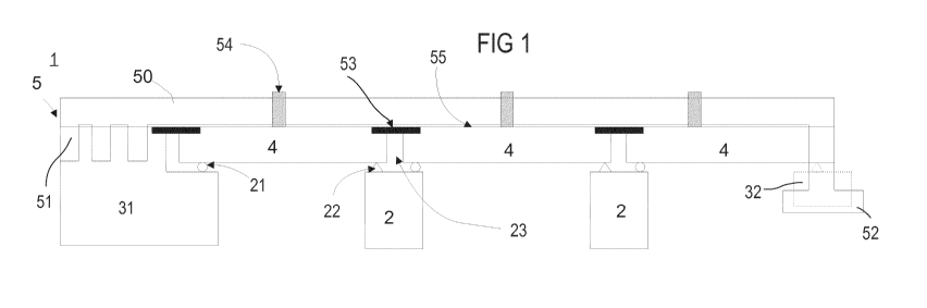
Figure 1 and Figure 2 schematically present an example of
embodiment of a running track 5 according to the invention in a
front and top view respectively. Said running track 5 is a
continuous track on a bridge structure 1, said bridge structure
1 comprising at least two bridge segments 4, a first abutment
31 situated at one end of said bridge 1 and a second abutment
32 situated at the other end of said bridge, and a load-bearing
structure formed from piers 2 distributed between the first
abutment 31 and the second abutment 32 to support said segments
4. In particular, said segments can rest at their ends on fixed
22 and/or sliding 23 support devices as known to a person
skilled in the art. Each segment is in particular separated
from the immediately adjacent segment 4 by a road joint 23. The
upper surface of said segments 4 thus forms a discontinuous
support surface for the running track 5.
CA 02928303 2016-04-21
2013P21880W0 div.
8
In a preferred embodiment of a running track 5 according to the
invention illustrated by Figures 1 to 3, said track 5
comprises:
- a continuous slab 50 extending from one end to the other
of said bridge 1 and resting on the upper surface of said
segments 4;
- an antifriction layer 55 situated beneath the continuous
slab 50 configured to act as an interface between the
upper surface of said segment 4 and the lower surface of
the continuous slab 50, said antifriction layer 55 thus
defining a slip plane for said continuous slab 50 and
allowing the latter to have at least a degree of
longitudinal freedom in relation to the upper surface of
said segment 4, said antifriction layer 55 extending
preferentially continuously beneath all of the lower
surface of said continuous slab 50;
- a crossing plate 53 situated beneath the continuous slab
50, in particular beneath the antifriction layer 55,
positioned so as to extend from one end of a segment to
the end of another directly adjacent segment so as to
cover the adjacent ends of said segments 4 in order to
compensate for flexion or rotation movements in the
supports of said segments 4.
Preferentially, the antifriction layer 55 comprises a first
geotextile layer 551 intended to be in contact with said
continuous slab 50, for example by being glued/fixed to the
lower surface of said continuous slab 50, and a second
geotextile layer 552 intended to be in contact with said
segments 4, for example by being glued to the upper surface of
said segments, said first and second geotextile layers 551, 552
sandwiching one or more Polyane (or geomembrane) layers 553.
Advantageously, the geotextile/Polyane/geotextile sandwich
configuration of the antifriction layer improves the sliding of
the continuous slab on said segments.
CA 02928303 2016-04-21
2013P21880W0 div.
9
Preferentially, the crossing plates 53 are extruded polystyrene
panels (Styrodur type). In particular, said segments 4 comprise
at their ends pockets 41 whose dimensions correspond to the
dimensions of the crossing plates 53 so that, when said
crossing plates 53 are inserted into said pockets 41, the upper
surface of said segment 4 and the upper surface of said
crossing plate 53 coincide or, in other words, are at the same
level so as to form a continuous surface. Advantageously, this
makes it possible to maintain continuity of level beneath the
continuous slab 50, hence promoting the sliding of the latter
on the continuous surface formed by the upper surfaces of the
segments 4 and the upper surfaces of the crossing plates 53.
A special feature of the running track 5 according to the
invention is that it comprises at least one anti-lift device 54
configured to be able to be rigidly connected to a segment 4,
for example using a system of bolts and anchorage bushes pre-
implanted in said segment 4, or by concrete reinforcement and
pouring in order to fix a part of said anti-lift device to said
segment 4. The anti-lift device 54 according to the invention
is also capable of limiting a translation or movement of said
slab 50 in a direction N perpendicular to the slip plane while
providing for a freedom of movement of said slab on the slip
plane defined by said antifriction layer 55. Owing to its
construction as a monobloc free from movement on the sliding
surface defined by the friction layer, the running track 5
according to the invention is particularly well adapted to
supporting a rail 6 of the LWR type (long welded rail) since
its surface providing for fixing of said rail has no
discontinuities.
Figures 4-6 present more detail of the constructional aspects
of preferred embodiments of the invention, in particular of
said anti-lift devices 54. Preferentially, an anti-lift device
CA 02928303 2016-04-21
2013P21880W0 div.
54 according to the invention comprises a body 542 designed to
be rigidly fixed/anchored directly or indirectly to said
segment 4 and a head 543, preferentially comprising a stop or
itself acting as a stop. Said head is in particular designed to
limit a movement of said slab 50 in the direction N
substantially perpendicular to said slip plane, said movement
being in particular non-zero and limited by said head 543 or
said stop.
Preferentially, said continuous slab 50 is a self-draining
slab. For this purpose, it comprises in particular at least one
drainage device 58 (represented in dotted lines) intended to
prevent the accumulation of water on said continuous track,
said drainage device being integrated into said slab 50 and
free from discharge beneath the slab 50 in order to guarantee
free movement on said slip plane. Said slab 50 is in particular
a slab with three distinct parts: two supporting parts A having
an upper surface forming a running surface for the wheels of a
vehicle intended to run on the bridge and one part B accepting
a means of guidance of said vehicle. Said parts A are thus in
particular intended to support the forces generated by the
movement of a vehicle on said bridge structure and have upper
faces, on which the wheels of said vehicle move, situated in
the same plane. The part B is in particular intended to accept
a guide rail 6, for example an LWR, the upper face of part B
being in particular in a plane situated beneath the level of
the plane defined by the upper faces of parts A. Said drainage
device 58 is in particular capable of evacuating on said
lateral sides of said slab 50 water accumulated on the upper
surface of parts A and/or B. Said drainage device comprises for
example a network of channels, for example hollowed out or
implanted prior to pouring in said parts A of the slab 50, and
describing a gentle slope between the level of the upper face
of part B upstream and a lateral end of the slab 50 downstream
so that the water can run from upstream to downstream by means
CA 02928303 2016-04-21
2013P21880W0_div.
11
of gravity. Preferentially, the upper surface of said part B
comprises at least one run-off gutter or channel, passing in
particular to each side of said part B and preferentially
located in the extension of one of said hollowed out or
implanted channels in said parts A in order to improve the flow
of water from said part B towards the lateral sides of the slab
50.
Preferentially, said continuous track comprises electrical
cable ducts 57 implanted in said continuous slab 50 and/or a
heating device 56 implanted beneath the upper surface of said
parts A so as to heat said upper surface of said parts A. Said
electrical cable ducts 57 provide for example for the passage
of electrical cables intended to heat a running surface of said
continuous track (e.g. Joule effect) or to act as a ground or
to supply electricity to guided vehicles intended to move on
said continuous track.
According to a preferred embodiment, said body 542 is a plate,
for example a metal plate, configured to be fixed either
directly to said segment 4, or to a lateral stop 541 of said
continuous slab, in particular for example by means of a device
for adjusting the height of said plate, said lateral stop 541
being itself fixed to said segment 4. According to this
preferred embodiment, said head 543 is for example fixed to an
end of said plate so as to be positioned opposite and
overhanging at least one part of one of the lateral sides of
the upper face of said continuous slab 50 as illustrated in
Fig. 4. Said anti-lift devices 54 are preferentially
distributed to each side of the continuous slab 50. The space
separating two immediately adjacent anti-lift devices 54 on the
same side of continuous slab 50 is preferentially determined by
calculation by means of finite element methods so as to make
the take-up of the stresses generated along said direction N
all along said continuous slab 50 uniform. In order to take up
CA 02928303 2016-04-21
2013P21880W0 div.
12
said stresses, different plate lengths can be used. Each of
said plates is preferentially positioned with respect to said
slab 50 so as, on the one hand, to have its end supporting said
head 543 overhanging the upper face of a lateral side of the
continuous slab and, on the other hand, to have its other end
fixed to a lateral stop 541 or directly to a bridge segment by
means or otherwise of a height adjustment device.
Preferentially, said head 543 has a substantially
parallelepiped shape and comprises in particular at least one
side opposite the upper face of said slab 50, which is parallel
to the latter, and able to contact said upper face of the slab
50 when the latter moves in said direction N, said side
possibly being in particular covered by a layer of antifriction
and compression-resistant material 544, for example Teflon. In
particular, said head 543 may comprise at least a first part
comprising at least an incompressible material intended to form
a vertical stop capable of taking up forces directed along said
direction N and exerted by the slab 50, and optionally a second
part comprising at least a compressible or elastic material
intended to damp the movement of said slab 50 along direction
N. Preferentially, said anti-lift device allows a free or
damped movement of said slab 50 in said direction N as far as
said stop or first part.
Preferentially, said continuous track 5 comprises continuous or
discontinuous lateral stops 541 distributed to each side of
said slab 50 in order to hold the latter laterally, each
lateral stop being in particular rigidly fixed to one or more
segments 4. In order to avoid the use of lateral stops, the
present invention also proposes another preferred embodiment
illustrated in Figures 5-6 and based on a different
constructional arrangement of the anti-lift device according to
the invention. According to this different constructional
arrangement, said head 543 of said anti-lift device 54 envelops
at least a part of said body 542 so as to create a coupling
CA 02928303 2016-04-21
2013P21880W0 div.
13
providing for a relative movement of said head 543 with respect
to said body 542 in a direction parallel to said slip plane,
while limiting the relative movement of the head with respect
to the body in a direction N perpendicular with respect to said
slip plane. For example, the body 542 of the anti-lift device
comprises:
- a base 71 intended to be fixed/anchored to said segment 4
for example by screwing or pouring concrete or by means
for example of anchorage bushes pre-implanted in said
segment 4 in order to rigidly connect said base 71 to said
segment 4;
- a cylindrical rod 72, rigidly fixed at one of its ends to
said base 71 and comprising at its other end a disk 73
with a radius greater than the radius of said cylindrical
rod 72 and with thickness E (E being the thickness of said
disk along said direction N);
said disk 73 and at least a part of said rod 72 being enclosed
in said head 543 of the anti-lift device 54. For this purpose,
said head 543 comprises a hollow cylindrical part 82 intended
to accept said cylindrical rod 72 and guide it, the end of said
hollow cylindrical part 82 directed towards said base 71 of the
body 542 of the anti-lift device 54 being open and its other
end being closed by a hollow cylindrical cap 83 with a radius
greater than the radius of said disk 73 of the body 542 of the
anti-lift device 54 and with an internal height approximately
equal to or greater than thickness E in order to be able to
accept said disk 73 so that the latter is held vertically while
permitting slight play along direction N and allowing the
latter to move along a plane parallel to said slip plane.
According to this other preferred embodiment, the interior of
said cylindrical cap 83 traps the disk 73 and acts as a stop.
Advantageously, the interior of said cylindrical cap 83 and/or
the hollow cylindrical part 82 =can be covered with an
antifriction material facilitating the relative sliding of the
body and the head when they are in contact. Preferentially,
CA 02928303 2016-04-21
2013P21880W0 div.
14
this anti-lift device is intended to be positioned beneath said
continuous slab, said body 542 being fixed to said segment 4,
and said head 543 being fixed to said slab. Of course, a person
skilled in the art would have been able to produce an inverse
device, with a body fixed to the slab and a head fixed to the
segment, or also applied the concept to a lateral stop, the
body then being fixed to the lateral stop and the head to said
slab, or vice versa. Figure 6 finally presents a top view of an
installation of one or more anti-lift devices 54 in said slab
50 according to this other preferred embodiment.
Preferentially, other constructional arrangements 54R, 54E for
the head 543 and the body 542 according to the invention can be
produced by a person skilled in the art, said other
constructional arrangements 54R, 54E all being characterized in
that they retain the feature of holding the head vertical with
respect to the body while permitting on the one hand slight
play along direction N, and on the other hand said relative
movement of the head with respect to the body in a plane
parallel to said slip plane when said anti-lift device is
mounted on/in the continuous running track according to the
invention. These other constructional arrangements 54R, 54E are
also illustrated in Fig. 6. For example, said body may include
a base intended to be fixed/anchored to said segment 4, said
base being attached to a rod or approximately vertical
structure surmounted by an approximately horizontal structure
with respect to said rod or vertical structure, said
approximately horizontal structure having regular thickness E,
oblong in shape, for example elliptical or rectangular, as
illustrated by references 54E and 54R respectively, the section
of said approximately horizontal structure along a horizontal
plane (i.e. parallel to the slip plane when said anti-lift
device is fitted to said running track) having dimensions
greater than the section of said rod or vertical structure
along a plane parallel to said horizontal plane. Said head
CA 02928303 2016-04-21
2013P21880W0 div.
itself has a shape suitable for enclosing at least a part of
said rod or approximately vertical structure and for
enclosing/trapping said approximately horizontal structure so
as to peLmit a relative movement of the head with respect to
said body, said movement permitted along the length of said
oblong shape being in particular greater than the movement
permitted along the width of said oblong shape. For this
purpose, said head 543 comprises a hollow part intended to
accept said rod or vertical structure and guide it, the end of
said hollow part directed towards said base of the body 542 of
the anti-lift device 54 being open and its other end being
closed by a hollow cap with dimensions greater than the
external dimensions of said approximately horizontal structure
and with an internal height approximately equal to or greater
than thickness E so as to be able to accept within it said
approximately horizontal structure. The hollow cap is thus
preferentially proportioned so that the movement allowed for
said approximately horizontal structure inside said cap is
greater in the direction of the longitudinal axis (length) of
said horizontal structure than its movement in the direction of
its transverse axis (width). According to these other
constructional arrangements 54E, 54R, the anti-lift device is
configured to be mounted in/on said continuous track so that
the longitudinal axis of the oblong structure is aligned with
the longitudinal axis of said track or slab. Advantageously,
these other constructional arrangements of the anti-lift device
according to the invention promote the longitudinal movement of
said slab compared to its transverse movement.
Advantageously, the anti-lift device 54 according to said other
constructional arrangements facilitates the construction of
said track 5. In fact, during the construction of the latter,
it is for example possible to position and then fix the body
542 of each anti-lift device 54 to a segment 4 of said bridge 1
or to a lateral stop 541, the head 543 of said anti-lift device
CA 02928303 2016-04-21
2013P21880W0 div.
16
remaining free at first. Then, subsequently, it is possible to
construct the continuous slab 50 so that it is rigidly
connected only to said head 543 of said anti-lift device. In
this way, the continuous slab 50 and said segment 4 are coupled
vertically so as to permit a vertical movement for the slab 50,
while allowing it simultaneously to move in a plane parallel to
said slip plane. In fact, since for example the rod 72 and the
disk 73 of the body 542 have radii smaller than the radii
respectively of the hollow cylindrical part 82 and the cap 83
of the head 543 of the anti-lift device, this difference in
radius permits a freedom of movement of the head 543 of the
anti-lift device with respect to said body 542 when the latter
is fixed to said segment 4. Preferentially, an elastic or
compressible material fills the space between the hollow part,
for example the hollow cylindrical part 82, and said rod 72
and/or between said cap 83 and said approximately horizontal
structure, for example said disk 73, so as to oppose a movement
of said rod 72 in said hollow part. For example and for this
purpose, the external circular surfaces of said rod 72 and/or
of said disk 73 are covered by a layer of said
elastic/compressible material. Said body 542 and said head 543
are themselves preferentially made from metal.
Preferentially, said continuous track 5 comprises, at each of
the ends of said continuous slab 50 along its length, one or
more abutment piers 51, 52 intended to take up longitudinal
forces appearing in said continuous slab 50. Said abutment pier
51, 52 may for example be anchored to an end abutment 31 of
said bridge or to a raft 32.
To sum up, the present invention proposes a continuous track on
a bridge structure comprising a slab completely detached from
the surface formed by an upper face of the deck, i.e. segments
of bridges, thus ensuring a free movement of said slab on said
deck while limiting a vertical and/or transverse movement of
CA 02928303 2016-04-21
2013P21880W0 div.
17
said slab, by means of anti-lift devices capable of taking up
normal forces on the deck exerted for example during lifting of
said slab 50 and additionally transverse forces, said anti-lift
devices being able in particular to cooperate with lateral
stops for said take-up of transverse forces. Said running track
according to the invention is thus characterized in that it may
comprise a plurality of anti-lift devices distributed along its
length, arranged for example laterally to each side of said
slab (50), as represented in Figures 1-4 and/or anchored in
said slab, for example as represented in Figures 5 and 6.