Note: Descriptions are shown in the official language in which they were submitted.
1
Amusement park ride with movable track section
The present invention relates to an amusement park ride, particularly for
fairs and amusement
parks. In particular the invention relates to a track section of an amusement
ride guided by rails.
Amusement equipment for rides frequently provide for the installation of fixed
rail sections, on
which vehicles are moved in a guided fashion, such as in roller coasters. DE
198 09 641 Al
discloses for example such an amusement ride, in which a passenger cabin
travels in a guided
fashion on rails over track sections with the track showing alternating
inclinations. The track
shows two track sections, projecting vertically upwards, which are connected
to each other in a
vertical level essentially by a semicircular arc section. In such amusement
rides frequently tiring
effects develop rather quickly for the passenger, primarily by the
periodically repeated upwards
and downwards motion.
In order to increase the attractiveness for the customer or rider there is the
trend to design the
track itself in a more mobile fashion. For example, EP I 364 691 B1 disclosed
a track section
arranged on a rocker, on which a vehicle with passengers travels from one end
to the other end
and back again to the first end, with the track similar to a seesaw being
pivoted back and forth
about a single pivotal axis. Even in such a track a tiring effect quickly
develops in the user,
because the motions follow a periodic and thus soon detected pattern. The
track progression on
which the vehicle rides is determined by the shape of the rail and the
stationary pivotal axis
about which the track is pivoted.
The objective of the following invention is therefore to provide an amusement
ride in which the
track progression cannot easily be predicted by the passenger and which thus
can offer
particular thrills to the rider.
This objective is attained in an amusement ride as described herein.
Advantageous
embodiments are also disclosed herein.
CA 2928335 2019-06-28
CA 02928335 2016-04-21
2
The amusement ride comprises a guidance track, which shows a first pivotal
axis for the mobile
guidance of the guide track as well as a second pivotal axis for the mobile
guidance of the guide
track. Furthermore, the amusement ride shows a first mobile fastening as well
as a second mobile
fastening. The guide track is fastened at the first pivotal axis with a first
mobile fastening in a
mobile and pivotal fashion and fastened at the second pivotal axis with the
second mobile
fastening in a mobile and pivotal fashion.
According to the invention, the first pivotal axis (6) is pivotal about at
least a first axial direction
and the second pivotal axis is pivotal about at least a second axial
direction. The track
progression is then not easily predictable by the passenger, which can offer
particular moments
of surprise. For example, such a mobile guide track can be adjusted such that
it tilts, resulting in
that the passenger is given the impression that vehicle and rider fall out of
the track, which
particularly at high elevations above the ground or in a water basin can lead
to particularly
amusing moments for the passenger.
The axis of the first axial direction may be arranged outside the guide track,
for example in a
mobile fashion, so that the first pivotal axis is pivotal about the axis of
the first axial direction.
The axis of the second axial direction may be arranged outside the guide
track, for example in a
mobile fashion so that the second pivotal axis is pivotal about the axis of
the second axial
direction. This way, for example a translational motion of the guide track can
be permitted. The
first fastening and the second fastening only need to be coupled to each other
via the first and the
second pivotal axis and the guide track. For the rest, they may be moved
independent from each
other.
Advantageously the pivotal axes of the amusement ride are also articulate such
that the guide
track is moved in a translational fashion. The rider is then given the
impression that suddenly no
longer the vehicle he/she is riding in is moving, which can lead to additional
moments of
surprise. For example, with this effect of a rail arranged in a water
reservoir the swinging on a
large wave can be simulated, which is not possible in devices that only allow
performing
pivoting motions.
CA 02928335 2016-04-21
3
The first axial direction can be arranged pointing perpendicular in reference
to the guide track at
the first pivotal axis, for example at the first pivotal axis.
On embodiment of the amusement ride according to the invention comprises a
guide track which
shows a first pivotal axis for the mobile guidance of the guide track, with
the guide track being
fastened in an articulate fashion at the first pivotal axis with a first
fastening, and with the first
pivotal axis furthermore being arranged pointing in a first axial direction,
perpendicular to the
direction of the guide track at the first pivotal axis, and being mobile
perpendicular to the first
axial direction. According to the invention the guide track comprises a second
pivotal axis for the
mobile guidance of the guide track, with the guide track being fastened at the
second pivotal axis
with a second fastening, and the second pivotal axis is arranged pointing in a
second axial
direction, perpendicular to the direction of the guide track at the second
pivotal axis, and being
mobile perpendicular to the second axial direction.
Unlike a mere to and fro pivoting motion, such a track can mimic for example
the actual swaying
motion of a ship on large waves.
The guide track shows at least one vehicle held at the guide track and guided
thereby in a mobile
fashion. Such an amusement device offers additional surprising moments for the
passenger in the
vehicle, because from the given progression of the guide track no conclusions
can be drawn
about the actual further progression of the vehicle. Contrary to a track
arranged on a simple
rocker, here the rider cannot draw conclusions about the progression of the
travel of the vehicle
simply by considering a rocker motion. This way, additional surprising moments
can be provided
for the passenger.
In an embodiment according to the invention the guide track is arranged
between the first and the
second pivotal axis, parallel in reference to a level which extends
perpendicular to the axial
direction of the first pivotal axis. The guide track may extend straight for
example between the
first and the second pivotal axis. Here, while the passenger rides on the
rail, its incline can be
variably adjusted with the help of the two pivotal axes. The rider then sees a
straight section of
track ahead, and while riding thereon it changes its incline. Of course, the
guide track can also be
CA 02928335 2016-04-21
4
extend in a curved fashion, with curved in this context representing that the
guide track is
distorted at least sectionally or that the guide track is arranged about a
straight axis, for example
on the jacket surface of a cylinder about the axis of the cylinder, helically
winding at least about
a section of the straight axis, i.e. the cylinder axis.
The first and/or the second pivotal axis may be mobile parallel and in
reference to the direction
of the guide track. This way, for example an additional level of freedom is
provided when the
guide track is moved for example with lifting rods.
In a preferred embodiment, the first axial direction is arranged parallel in
reference to the second
axial direction.
The fasteners of the guide track are arranged adjacent to each other, with the
first fastening of the
guide track being arranged adjacent to the second fastening of the guide
track. Between the first
and the second fastening the guide track shows preferably no additional
fastening fixing the
position of the guide track in reference to the erection site of the guide
track, however at least no
stationary fastening. Due to the fact that between the first and the second
pivotal axis the guide
track shows no locally fixed axial fastening, the impression of a collapsing
track can also be
realized for the passenger, for example by both pivotal axes moving downwards
simultaneously.
In this case, the guide track is freely carried between the first fastening
and the second fastening.
The first fastening is for example formed by a first lifting rod or by first
lifting rods, arranged
pivotally at the first pivotal axis. The second fastening can be formed by a
second lifting rod or
by second lifting rods, arranged pivotally at the second pivotal axis.
In order to create a relatively simple amusement ride, the first lifting rod
and/or the first lifting
rods may be connected to a stationary arranged motor drive, or alternatively
connected to a
motor drive guided at a stationary rail, with the angle of the first lifting
rails changing in
reference to the guide track when it the motor switched on. Such a motor may
move back and
forth for example the ends of the first lifting rod/lifting rods opposite the
pivotal axis along a
bottom rail connected fixed to the bottom, and here changing the angle between
the first lifting
CA 02928335 2016-04-21
rod/the first lifting rods and the bottom rails, which can lead to a change
of' the track elevation
and the track incline of the guide track. In order to change the elevation of
the track and the
incline of the guide track the first and/or second lifting rods may also or
additionally be guided in
a respectively stationary fixed, pivotal guide sheath.
The first and/or second fastenings may of course also show other fixed or
adjustable coupling
elements, such as con-rods, shears, or the like.
In one advantageous embodiment the first and/or second lifting rods show
lifting cylinders, or
they are connected to lifting cylinders. When the lifting rods show lifting
cylinders, the raising
and lowering of the guide track can occur even without an additional drive,
for example.
In order to allow quickly accelerating or braking the vehicle at the guide
track, the vehicle shows
for example wheels by which it can be moved on the guide track. The vehicle
may furthermore
show an additional drive engine and/or brakes. This way it is possible to
accelerate and/or brake
the vehicle independent from the progression of the guide track.
The guide track may show a reverse lock in order to fix the vehicle guided
thereon at a certain
point. Such a reverse lock creates an additional thrill for the rider.
A guide track is preferably arranged at least partially in a water reservoir,
with it at least partially
being arranged extending underneath the water level of the water reservoir.
The guide track may
be arranged extending completely in the water and for example extend
underneath the water
level. The guide track may for example be also arranged traveling into the
water reservoir and
movable out of said water reservoir. It is also possible to rotate the guide
track in the water
reservoir; for example, parallel to the water surface, or is tilted in the
water reservoir in order to
simulate the feeling of falling out, for example. A combination with water
gives the passenger an
additional amusement.
In this case, the vehicle is therefore advantageously a boat. The mobile guide
track can then
provide the feeling of a ship sailing on high waves.
CA 02928335 2016-04-21
6
The guide track may also be embodied as the watercraft itself. The first
mobile fastening could
be a first rope fastened at the watercraft, the second mobile fastening could
be a second rope
fastened at the watercraft. In this case the watercraft could be arranged in a
mobile fashion in a
water reservoir filled with water and pulled by the first and/or the second
rope. The two ropes
can be fastened to winches, which are arranged such that the watercraft can be
tilted such that the
watercraft can be entered for example in that it is tilted in the direction
towards the entrance as
explained in greater detail in the following in connection with on one of the
exemplary
embodiment.
The vehicle is advantageously moved from one end of the guide track to the
other end of the
guide track. This additionally ensures entertainment because the entire track
and not only a
section thereof is traveled. Thus, in a preferred amusement ride the guide
track is connected at
one of its ends to another guide track when the vehicle has reached at last
one end of the guide
track. Then the vehicle performs no back and forth motion on the guide track
but moves in a
predetermined direction and here travels only one once on the moved guide
track and therefrom
changes to another guide track.
In another embodiment the guide track may be embodied as a water slide. Then
it may show
several channels, preferably arranged parallel to each other and embodied as
individual slides.
Each of the channels may show one or more differently deep depressions. For
example, each of
the channels may accept one passenger, or also several passengers, for example
on a hoop, or be
intended for an individual rider. On such a water slide, therefore several
persons can slide down
the waterslide side-by-side. In one embodiment the speed of sliding can be
controlled via the
individual channels, preferably separately, by the supply of the water volume.
Additionally, such
a water slide can ensure, for example in the sliding direction during the
sliding process by way of
a change of its decline according to the invention that the sliding speed of
the rider can
additionally be increased or reduced. For example, competitions can be held
between riders
arranged sliding on different individual slides. In the embodiment in which
the depths of the
individual depressions of adjacent individual slides are embodied differently,
the neighboring
rider can partially be invisible for the rider and then suddenly reappear,
which may lead to
7
additionally thrilling moments during the joint ride. A potential embodiment
would also be a
contact option. by which each sliding party could confirm completion of the
ride and thus a
timer for the competition could be provided.
At the ends of the guide track embodied as a waterslide with several
individual slides extensions
and/or brake sections may be embodied so that starting at a certain elevation
of the guide track
the rider can automatically slide out. If necessary, additional holding
devices or automatically
controlled gates may be provided. Safety nets may also be provided at the
sides of the guide
track and/or at its ends.
According to one aspect of the invention, there is provided an amusement ride,
comprising a
guide track which has a first pivot axis for movably guiding the guide track
as well as a
second pivot axis for movably guiding the guide track, a first movable
mounting, as well as a
second movable mounting, wherein the guide track is mounted movably and
pivotably on the
first pivot axis by means of the first movable mounting and is mounted movably
and
pivotably on the second pivot axis by the second movable mounting, wherein the
first pivot
axis is pivotable about at least one first axial direction and the second
pivot axis is pivotable
about at least one second axial direction.
The motion effects of the guide track, for example the waterslide, can be
freely programmable
so that different progressions of motion can be realized.
According to one aspect of the invention, there is provided an amusement ride,
comprising a
guide track which has a first pivot axis for movably guiding the guide track
as well as a second
pivot axis for movably guiding the guide track, a first movable mounting, as
well as a second
movable mounting, wherein the guide track is mounted movably and pivotably on
the first pivot
axis by means of the first movable mounting and is mounted movably and
pivotably on the
second pivot axis by the second movable mounting, wherein the first pivot axis
is pivotable
about at least one first axial direction and the second pivot axis is
pivotable about at least one
second axial direction wherein the first mounting is formed by first lifting
rods, which are
CA 2928335 2019-06-28
7a
arranged pivotably on the first pivot axis, and in that the second mounting is
formed by second
lifting rods which are arranged pivotably on the second pivot axis.
The designations used in the following description, such as top, bottom, left,
and right and the
like refer to the exemplary embodiments and shall not be considered limiting
in any way, even
when they refer to a preferred embodiment.
In the following, the invention is explained in greater detail based on a
drawing.
It shows:
Fig. I a cross-section of an amusement ride according to the invention,
Fig. 2 two lifting devices embodied as shears,
Fig. 3 an amusement ride embodied as a waterslide in a cross-section
perpendicular in
reference to the direction of motion,
Fig. 4 a waterslide along the direction of motion,
Fig. 5 another embodiment of the amusement ride according to the invention.
CA 2928335 2019-06-28
8
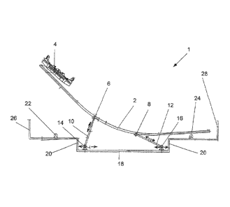
Fig. 1 shows a schematic lateral cross-section of an amusement ride 1 at a
certain point of time
with a guide track 2, on which a vehicle 4 moves in a guided fashion. The
guide track 2 is
provided at a first pivotal axis 6 as well as at a second pivotal axis 8 with
fastenings 10, 12. The
first pivotal axis 6 is fastened in a mobile fashion with the first fastening
10, the second pivotal
axis 8 is fastened in a mobile fashion with the second fastening 12. In the
example shown the
first fastening 10 is a first lifting rod 10 and the second fastening 12 is a
second lifting rod 12.
A first motor drive 14 is arranged at the end of the first lifting rod 10
opposite the pivotal axis
6. A second motor drive 16 is arranged at the end of the lifting rod 12
opposite the second
pivotal axis 8. The two motors 14, 16 are embodied as linear motors, which are
formed in a
bottom rail 18 connected fixed to the ground, which is embodied in a
depression 20 of the
amusement ride 1, mobile back and forth. When the two linear motors 14, 16
move towards
each other in the bottom rail 18, the angle changes between the track 2 and
the first lifting rod
as well as the angle between the track 2 and the second lifting rod 12. In the
present example
the lifting rods show a fixed length, however they may also show a variable
length. By changing
the angle between the track 2 and the lifting rods 10, 12 the track 2 is
guided in a mobile fashion
at the first pivotal axis 6 and at the second pivotal axis 8. A left track
support 22 and a right
track support 24 ensure that the guide track 2 can be pivoted in an articulate
fashion between
the two track support points. A left stop edge 26 and a right stop edge 28
ensure in the present
exemplary embodiment that the vehicle 4 cannot leave the track 2.
Of course it is also possible to provide the amusement ride 1 as a section of
a longer track. For
example, instead of the left stop edge 26 at one end of the guide track 2 here
a first guide track
may be provided, from which the vehicle 4 reaches the track section, the guide
track 2. As soon
as the vehicle 4 is located on the guide track 2, the guide track 2 can be
raised by the lifting
devices 10, 12, 14, 16, for example at the left side. Optionally, until the
guide track 2 has been
lifted, the vehicle 4 may be held at a certain point of the guide track 2 and
then be released. The
vehicle 4 may then travel on the guide track 2 until reaching the other end.
At the moment the
vehicle 4 reaches the other end of the guide track 2, the guide track 2 is
connected to a second
guide track so that the vehicle 4 can immediately continue traveling on the
second guide track.
This way, many additionally interesting effects can be integrated in a track.
CA 2928335 2019-06-28
CA 02928335 2016-04-21
9
The guide track 2 may also be guided directly into a water reservoir during
the tilting process, for
example, so that it ultimately is arranged at least partially underneath the
water level of the water
reservoir. The vehicle 4, for example moving from the left towards the right,
may be embodied
as a boat and can then directly continue moving on the track 2.
The invention was explained based on preferred exemplary embodiments without
being limited
to these exemplary embodiments. The features of the individual embodiments can
be freely
combined or exchanged with functionally equivalent features of other
embodiments, assuming
compatibility.
For example the vehicle can also be held redundantly via the return block when
it has reached
the end of the guide track 2, and for example automatically be disconnected
when an apex has
been reached.
The motion of the pivotal points 6, 8 can occur for example via lifting
cylinders or con rods or
ropes. The lifting rods 10, 12 may be arranged aligned parallel in reference
to each other and for
example coupled to each other via lateral rods showing a fixed length.
Instead of one or in addition to one or more linear motor drives the amusement
ride may show a
pneumatic device for raising and lowering the first and second pivotal points.
The guide track 2 may also show additional weights between the first pivotal
axis 6 and the
second pivotal axis 8 in order to ensure that the center of gravity of the
guide track 2 is always
and in any case is located between the two pivotal axes 6 and 8, regardless of
the present position
of the vehicle 4 and independent from the present position of the guide track
2.
One trained in the art will know many such or similar embodiments of the
mobile guide track 2,
without here leaving the concept of the invention.
CA 02928335 2016-04-21
Fig. 2 shows two of them embodied as shearing mechanisms, which can stabilize
the stroke
direction of the lifting cylinder 30. Such mechanisms can for example be
provided as lifting
mechanisms for the motion of the guide track 2.
The left embodiment of Fig. 2 shows a lifting cylinder 30, which is connected
to a first shearing
arm 32 at a joint 33. The first shearing arm 32 is connected to the joint 34
in an articulate fashion
via a second shearing arm 36. The second shearing arm 36 is fastened in an
articulate fashion to
the other end of the lifting cylinder 30 at a stationary fixation 38. The
joint 34 can for example be
guided in a guiding groove (not shown) of a stationary arranged plate (not
shown either) so that
the lifting device can be operated such that the joint 33 is mobile diagonally
upwards and
downwards.
The right embodiment of Fig. 2 shows the example of another lifting mechanism.
The shearing
arms 40, 41 are connected to each other in an articulate fashion at a joint
42. The shearing arms
43, 44 are connected in an articulate fashion to another joint 45 embodied as
a stationary
fixation. The shearing arms 40, 43 are connected in an articulate fashion via
a joint 46 to the
lifting cylinder 47. The shearing arms 41 and 44 are also connected in an
articulate fashion via a
joint 48 to the lifting cylinder 47. By changing the stroke of the lifting
cylinder 47 here for
example the distance can be varied between the joints 42 and 45.
Fig. 3 shows another amusement ride 1 according to the invention in a cross-
section
perpendicular in reference to the direction of motion of the passenger 50. The
amusement ride 1
shows a guide track 2 embodied as a waterslide 51, with embodied channels 52a,
52b, 52c, 52d
arranged parallel side-by-side and embodied as individual slides. Each channel
52a, 52b, 52c,
52d shows in the direction of travel one or more depressions 54 (indicated in
dot-dash lines)
embodied with different depths. The waterslide 51 shows further safety nets 56
at its lateral
boundaries, which ensure that the passengers cannot fall out when the slide
moves for example
laterally. The waterslide 50 is further supported in an articulate fashion in
a bottom splash 58,
which is anchored in this exemplary embodiment via the ground anchors 59 at
the floor.
Alternatively the waterslide 51 can also be connected fixed to the bottom
splash 58. The bottom
CA 02928335 2016-04-21
11
splash 58 may alternatively show articulate lifting cylinders instead of
ground anchors 59, which
allow moving the bottom splash 58 in reference to the floor.
Fig. 4 shows a side view of the waterslide along the direction of motion of
the passenger 50. Via
an entrance 60 of the waterslide 51, which may be embodied slightly widened,
the passenger 50,
who may for example move in a watercraft or may also be sitting on the floor
of the water slide
50, can glide in a guided fashion on a channel 52a of the waterslide 50, and
can then ride along
the direction of motion (in Fig. 4 from the right to the left, and/or from
left to right) following the
channel 52a, which shows a first number of depressions 54 embodied with
different depths,
(indicated in dot-dash lines in Fig. 4). At the end of the channel 52a the
passenger 50 leaves the
waterslide 51 via an outlet 62, embodied as a brake section. A second
passenger can for example
be guided over the entrance 60, for example to the channel 52b of the
waterslide 50, and then
ride along a second number of depressions 54 embodied with different depths in
the direction of
motion (also shown in dot-dash lines in Fig. 4). This way several passengers
can ride side-by-
side in different channels with different speeds down the waterslide.
In a preferred embodiment the individual channels 52a, 52b, 52c, 52d of the
water slide 51 may
be impinged with different volumes of water per time unit, in order to more or
less accelerate the
passenger 50, for example. In one advantageous embodiment the passenger could
already during
the ride through the channels, for example via sensor elements arranged in the
channels, control
his/her ride independently by contacting them during the ride.
It is discernible from the above-explained exemplary embodiments that the
guide track 2 can
rotate both in the longitudinal direction and/or in its height and/or about
its own axis, so that a
passenger in the vehicle 4, in case of an appropriate arrangement of the
lifting device explained,
can seemingly be subjected to undefined progressions of motion. Although in
the above-stated
exemplary embodiments it is always discussed that the entire amusement ride I
is placed on a
stationary platform with a bottom rail 18, it is of course also possible that
the bottom rail 18 is
fastened on a rotating platform.
CA 02928335 2016-04-21
12
Fig. 5 shows an exemplary embodiment of another implementation of the
amusement ride
according to the invention. A guide track (2) embodied as a watercraft (2) is
fastened at a first
fastening (10) embodied as a first pulley (10) and pivotal at the first
pivotal axis (6). The first
pivotal axis (6) is embodied as an opening for a rope (6) at one end of the
watercraft (2). The
first pulley can for example be connected to a first winch (not shown). The
second pivotal axis
(8) may be embodied at the other end of the watercraft (2) as a second opening
for a rope (8) and
fastened at a second pulley (12) embodied as a second mobile fastening (12).
The second pulley
(12) is connected to a second winch (64). The watercraft (2) is arranged
floating on a water
surface (66).
In order to allow that passengers (50) can reach the watercraft (2) and the
entrance (50) via the
pier (68), the second pulley (12) is rolled up on the second winch (64), which
in the exemplary
embodiment is arranged underneath the water surface (66), to such an extent
that the pier (68)
and the entrance (60) of the watercraft (2) are arranged approximately on the
same level above
the water surface (66). A buffer (70) ensures that by a back and forth motion
of the watercraft (2)
on the water surface (66) the watercraft (2) is not damaged at the edge of the
pier (68). The
passenger (50) then reaches, for example on or with the loop, the entrance
part of the watercraft
(2). For an additional amusement of the passenger (50) the watercraft (2) may
be embodied for
example as a waterslide (2), for example as shown in the exemplary embodiment
of Fig. 4. As
soon as the passenger (50) has reached the entrance (60) of the watercraft
(2), the second pulley
(12) is quickly unrolled from the second winch (64) so that the entrance (60)
of the watercraft (2)
pivots upwards and the passenger (SO) slides or can slide for example along
the guide track (2) in
the direction of the exit (62). While the second winch (64) is quickly
unwound, for example the
first winch can be quickly wound up so that the passenger (50) can leave again
the watercraft (2)
= via the exit (62) at the side opposite the pier at the side of another
pier arranged at the opposite
side of the watercraft (2).
Of course it is also possible that by a repeated back and forth pivoting of
the watercraft (2) the
passenger (50) is repeatedly moved back and forth on the guide track (2) and
for example at the
end of the amusement is thrown into the water (66) via the exit (62).
CA 02928335 2016-04-21
13
The invention has been explained based on preferred exemplary embodiments
without being
limited to these exemplary embodiments. The features of individual embodiments
can be freely
combined with features of other embodiments in order to form new embodiments
to the extent
compatibility is given. For example, the watercraft in Fig. 5 can be embodied
as a waterslide as
in Fig. 4 or as a guide track as in Fig. 1, for example a vehicle (4) in which
the passenger takes a
seat. The first and/or second pulley shown for example in Fig. 5 may also be
replaced by a lifting
device with lifting cylinders. One trained in the art knows numerous
deviations and embodiments
of the device according to the invention, without here leaving the concept of
the invention.
List of reference characters
1 amusement ride
2 guide track, waterslide, watercraft
4 vehicle, boat
6 first pivotal axis, opening for a rope
8 second pivotal axis, opening for a rope
first lifting rod, mobile fastening, pulley
12 second lifting rod, mobile fastening, pulley
14 first motor drive
16 second motor drive
18 bottom rail
depression
22 left track support
24 right track support
26 left stop edge
28 right stop edge
lifting cylinder
32 shearing arm
33 joint
34 joint
36 shearing arm
38 stationary fixation
shearing arm
41 shearing arm
42 joint
CA 02928335 2016-04-21
14
43 shearing arm
44 shearing arm
45 stationary fixation
46 joint
48 joint
50 passenger
51 waterslide
52a channel
52b channel
52c channel
52d channel
54 depression
56 safety net
58 bottom splash
59 bottom anchoring
60 entrance, inlet
62 exit, outlet, brake section
64 winch
66 water surface
68 pier
70 buffer