Note: Descriptions are shown in the official language in which they were submitted.
81796304
ADAPTIVE FREQUENCY RESPONSE, ADAPTIVE AUTOMATIC LEVEL CONTROL
AND HANDLING RADIO COMMUNICATIONS FOR A HEARING PROTECTOR
Background
People frequently wear hearing protection when they are in loud or noisy
environments.
Hearing protection can reduce the amount of noise the user's ears are exposed
to. In some cases
the user might want to hear some noises, such as a conversations or commands
from people around
them. If the user is wearing hearing protection, hearing these desirable
noises can be difficult or
impossible. Therefore, there is a need to allow the user of hearing protection
to still be able to hear
some external noises, while still reducing the loud or undesirable noises.
Summary
According to an aspect of the present invention, there is provided an
apparatus for hearing
protection, comprising: a microphone disposed on the apparatus, the microphone
configured to
pick up an input sound wave from the environment and convert the input sound
wave to an
incoming signal; a processor, configured to apply a band pass filter to the
incoming signal to create
an output signal; a speaker disposed on the apparatus, the speaker configured
to produce an output
from the processor; wherein the band pass filter is selected from a plurality
of band pass filters,
wherein selection of the band pass filter is based on an average amplitude of
the incoming sound
wave; wherein at least one of the band pass filters for larger amplitudes is
more narrowly focused
on a selected range of frequencies than at least one of the band pass filters
for smaller amplitudes.
Sound external to a hearing protection headset can be input by one or more
microphones
on the headset. The ambient external sound or background noises can be
monitored, analyzed and
filtered so that a user of the headset can better hear human voices.
In one example, an apparatus for hearing protection, includes a microphone
disposed on
the apparatus. The microphone is configured to pick up an input sound wave
from the
environment and to convert the input sound wave to an incoming signal. The
apparatus also
includes a processor that is configured to apply a band pass filter to the
incoming signal to create
an output signal. The apparatus can further include a speaker disposed on the
apparatus. The
speaker is configured to produce the output from the processor. The band pass
filter, applied by
the processor, is selected from a plurality of band pass filters. The
selection of the band pass filter
is based on an average amplitude of the incoming sound wave. At least one of
the band pass filters
for larger amplitudes is more narrowly focused on a selected range of
frequencies than at least one
of the band pass filters for smaller amplitudes.
- 1 -
Date Recue/Date Received 2021-05-17
81796304
In one example, an apparatus for hearing protection, includes a microphone
disposed on
the apparatus and configured to pick up an input sound wave from the
environment and convert the
input sound wave to an incoming signal. The apparatus also includes a
processor, configured to
apply a band pass filter to the incoming signal wherein frequencies of an
output signal of the band
pass filter vary depending on an amplitude of the incoming signal. The process
is also configured
to perform one of two steps. The first option is detecting an impulse noise
when the amplitude of
the input surpasses an impulse detection threshold, when an impulse noise is
detected the output is
suppressed for a period of time, wherein the suppression period of time
depends on a volume level
setting selected by the user. The second option is keeping the gain of an
automatic level controller
constant when the audio device input is below a gate threshold, and the output
reduced to an ALC
maximum level when the output would otherwise have been above the ALC maximum
level. The
apparatus also includes a speaker disposed on the apparatus, the speaker
configured to produce the
output from the processor.
- la-
Date Recue/Date Received 2021-05-17
81796304
In one example, an apparatus for hearing protection, includes means for
picking up an
input sound wave from an environment, means for converting the input sound
wave to an incoming
signal, means for selecting a band pass filter from a plurality of band pass
filters, means for
applying the selected band pass filter to the incoming signal to create an
output, and means for
converting the output to an output sound wave. The band pass filter is
selected from a plurality of
band pass filters based on an average amplitude of the incoming sound wave.
The band pass filters
for larger amplitudes are more narrowly focused on a range of frequencies.
Brief Description of the Drawings
The invention may be more completely understood in connection with the
following
drawings, in which:
FIG. 1 is a perspective view of the headset, according to an embodiment.
FIG. 2 is a perspective view of the headset, according to an embodiment.
FIG. 3 is a block diagram of a process, according to an embodiment.
FIG. 4 is a graph of audio filter behavior, according to an embodiment.
FIG. 5 is a graph of audio filter behavior, according to an embodiment.
FIG. 6 is a graph of audio filter behavior, according to an embodiment.
FIG. 7 is a block diagram of a process, according to an embodiment.
FIG. 8 is a graph of audio filter behavior, according to an embodiment.
FIG. 9 is a block diagram of a process, according to an embodiment.
FIG. 10 is a graph of audio filter behavior, according to an embodiment.
FIG. 11 is a block diagram, according to an embodiment.
FIG. 12 is a graph of audio filter behavior, according to an embodiment.
While the invention is susceptible to various modifications and alternative
forms, specifics
thereof have been shown by way of example and drawings, and will be described
in detail. It
should be understood, however, that the invention is not limited to the
particular embodiments
described. On the contrary, the intention is to cover modifications,
equivalents, and alternatives
falling within the spirit and scope of the invention.
Detailed Description
The embodiments of the present invention described herein are not intended to
be
exhaustive or to limit the invention to the precise forms disclosed in the
following detailed
description. Rather, the embodiments are chosen and described so that others
skilled in the art can
appreciate and understand the principles and practices of the present
invention.
The publications and patents disclosed herein are provided solely for their
disclosure.
Nothing herein is to be
- 2 -
Date Recue/Date Received 2021-11-23
CA 02928698 2016-04-25
WO 2015/065882 PCT/US2014/062353
construed as an admission that the inventors are not entitled to antedate any
publication and/or patent,
including any publication and/or patent cited herein.
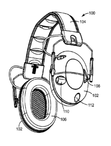
FIG. 1 is a perspective view of a headset 100. In an embodiment, the headset
100 can include an
ear cup 102 and a headband 104. The headset 100 can include two ear cups 102.
The headband 104 can
couple a first ear cup 102 with a second ear cup 102. The headband 104 can be
arced, such as to extend
over the top of a user's head while the headset 100 is in use. The headband
104 can be flexible, such as to
allow the user to spread the first ear cup 102 from the second ear cup 102
when the user is putting on the
headset 100. The headband 104 can include padding, such as to at least
partially conform to the user's
head and increase the user's comfort.
The ear cups 102 can be configured to fit at least partially around a user's
ear, and be disposed on
the side of a user's head while in use. The ear cup 102 can define a cavity.
The cavity can be configured
for a user's ear, a human ear, to fit within, while the user is wearing the
headset 100. The ear cup 102 can
include a seal ring 106. The seal ring 106 can be ring shaped, such as to
extend around the user's ear.
The seal ring 106 can be flexible and able to conform to the user's head. The
seal ring 106 can provide a
seal between the ear cup 102 and the user's head, such as to reduce the amount
of noise or sound waves
that reach the user's ear, thereby at least partially protecting the user's
ear from external noises. The seal
ring 106 can include leather, cloth, rubber, plastic, or a polymer, such as
polyurethane.
In an alternative embodiment, the headset can include a housing that is
configured to fit at least
partially within the outer portion of a user's ear, such as within a portion
of the auricle or pinna. In an
embodiment, the headset can include two housings, such as a right housing
configured to fit at least
partially within the user right ear and a left housing configured to fit at
least partially within the user left
ear. In an embodiment, the right housing and left housing can be substantially
identical, such that the
right housing can be used in association with the left ear and the left
housing can be used in association
with the right ear.
The headset 100 can include a microphone 108. In one embodiment, one or both
of the ear cups
102 can include a microphone 108. In an embodiment, there is one microphone
108 on each of two ear
cups 102. In an embodiment, there can be more than one microphone 108 on one
or both of the ear cups
102. in one embodiment, one or more microphones 108 are located at other
locations on the headset 100.
The microphone 108 can be disposed on the outside surface of the ear cup 102
opposite the cavity. The
microphone 108 can pick up sound and noise from the surrounding environment.
The microphone 108
can be inset, such that the microphone 108 does not extend past the outer
surface of the ear cup 102. In
an embodiment with two ear cups 102, each ear cup 102 can include a microphone
108. In another
embodiment with two ear cups 102, only one ear cup 102 includes a microphone
108. In another
embodiment with two ear cups 102, one microphone 108 is positioned on a
headband portion. The noises
and sounds picked up by the microphone 108 can be relayed to the user through
a speaker in the cavity of
the ear cup 102.
-3-
CA 02928698 2016-04-25
WO 2015/065882 PCT/US2014/062353
One of the ear cups 102 can include a knob 110. The user can rotate the knob
110 to control the
electronics of the headset 100, such as to turn the electronics "ON" or "OFF",
or to increase or decrease
the volume from the speakers in the ear cups 102.
The ear cups 102 can include an input connection 112. The input connection 112
can allow a
user to connect an external audio device into the headset 100, such as an
AM/FM radio, a two-way radio,
an MP3 player, a cell phone, or the like. The user can hear the external audio
device through the one or
more speakers disposed in the ear cups 102. In an embodiment, the input
connection 112 can
accommodate a 3.5 mm audio input. In an embodiment, the external audio device
can be connected to the
headset 100 through a wireless connection, such as Bluetooth connection. In an
embodiment, the external
1 0 audio device can be built in or integral with the headset 100.
Despite the presence of the ear cups forming a seal against the user's head,
some sound waves
will travel through the bone and open spaces of the user's skull to reach the
ear canal, such as through the
cranium, mouth or nose. Some sound waves come through the sealing rings, the
ear cups, or other
physical mechanisms. The level of sound traveling through these other
pathways, referred to a leakage
sound, is not reduced by hearing protection worn over or in the ears, such as
the headset 100 or ear plugs.
So, a portion of the sound will be beard as leakage sound conducted through
these other pathways, even if
sufficient hearing protection is worn so that the same sound is not heard as
sound conducted through the
environment to the ear. Around 40 dB is the maximum reduction that can be
achieved assuming a perfect
hearing protector, because leakage sound through the skull will still reach
the ear canal. If a sound is
above 40 dB, it will reach the ear canal even if hearing protection is worn. A
typical decibel level of a
gunshot is about 149 dB (typically between 140 dB and 170dB).
A generally accepted safe level of sound to reach the ears is an average of
about 85 dB over 8
hours, though different sound levels are considered safe by government,
medical or other entities in
different contexts and averaged over different time periods, such as 80 dB, 90
dB or 100 dB. Similarly, a
generally accepted safe level of sound to reach the ears is an instantaneous
level of 114 dB, though
different levels are also considered safe in different contexts and by
different entities, such as 100 dB, 110
dB, or 120 dB. The occurrence of sound leakage can be accounted for when
determining the level of
sound to produce using the speakers in the ear cups of headset 100. For
example, a portion of the safe
sound level can be allocated to be received as leakage, and then sound
produced by the speakers will
allocated the other portion of the safe sound level. In one example, half of
the safe sound level is
allocated to be received as leakage. The decibel scale is a logarithmic scale,
so every 3 dB drop in sound
level reduces the incoming noise by half. Using the example of a safe sound
level of 85 dB and a leakage
allocation of 50%, one option is for one half (82 dB) to be allocated to
leakage and for a maximum of the
other half (82 dB) to be provided by the speakers. In this example, the output
of the speakers will be
limited to 82 dB.
-4-
CA 02928698 2016-04-25
WO 2015/065882 PCT/US2014/062353
A perspective view of the headset 100 is shown in FIG. 2, from a different
perspective angle than
what is shown in FIG. 1. The ear cups 102 can include a battery compartment
214. The battery
compartment 214 can house one or more batteries. The batteries can be used to
power the electronic
components of the headset 100. In an embodiment, a plurality of AAA batteries
can be disposed within
the battery compattment 214. In an embodiment, the headset 100 can use lithium
ion batteries, AA
batteries, rechargeable batteries, non-rechargeable batteries, or a
combination of these different batteries.
A battery door 216 can at least partially enclose the battery compartment 214.
The battery door 216 can
be configured to be removed from the headset 100 when access to the batteries
are desired, such as to
replace the batteries.
Each ear cup 102 can include a speaker 218. The speaker 218 can produce an
output, such as a
sound wave. Incoming sound and noise picked up by each microphone 108 can be
processed, such as to
eliminate at least some of the noise and produce an output through the speaker
218. As used herein, the
term sound refers to desirable audio information while the term noise refers
to undesirable audio
information. The speaker 218 can provide sound to the user, such as desirable
audio. Desirable audio can
include conversations, commands, warnings or other communications, such as
communications between
two people. The input from each microphone can be processed to eliminate at
least some of the noise,
such as undesirable noises. Undesirable noises can include mechanical noises,
noises from ventilation
systems, distant conversations, impulse noises, grinding, squeaking, engine
noises, gun shots, explosions
and the other similar noises.
The speaker 218 can relay sounds from the surrounding environment picked up by
the
microphone 108. The speaker 218 can relay sounds from an external audio device
connected from the
input connection 112. The output from the speaker 218 can be limited to a
maximum output level, such
as to protect the user's ears. In different embodiments, the maximum output
level from the speaker 218
due to sound from the microphone can be at least 80 dB(A), not more than 90
dB(A), at least 70 dB(A),
not more than 100 dB(A), and combinations of these constraints. In an
embodiment, the output from the
speaker 218 is limited to 82 dB(A) when the ambient sound level is less than
106 dB(A), regardless of
how high the user has the volume turned up. In an embodiment, the output from
the speaker 218 is limited
to 85 dB(A) when the ambient sound level is less than 106 dB(A), regardless of
bow high the user has the
volume turned up. In an embodiment, the output from the speaker 218 is limited
to 82 dB(A), regardless
of how high the user has the volume turned up. In an embodiment, the output
from the speaker 218 is
limited to 85 dB(A), regardless of how high the user has the volume turned up.
In an embodiment, the
output from the speaker 218 can be limited to 82 dB(A) when an external audio
device is connected to the
input connection 112. The sounds picked up by the microphone 108 can be
processed before they are
produced as output from the speaker 218. The processing can increase the
quality or clarity of what the
user hears, such as by reducing background noise, suppressing impulse noises
or keeping an input level
constant. In one embodiment where each of two ear cups 102 has a microphone
108, the incoming sound
-5-
CA 02928698 2016-04-25
WO 2015/065882 PCT/US2014/062353
and noise is processed by a single processor. In another embodiment where each
of the two ear cups 102
has a microphone 108, the incoming sound and noise is processed by separate
processors applying the
same algorithms.
In another example, a hearing protector having one or more of the processing
functions as
described herein uses an in-ear structure rather than an over-the-ear, cup
structure. In such an example,
an ear plug structure can be used to reduce the sound waves reaching the inner
ear. A speaker can be
located on a portion of the in-ear structure that faces the inner ear, and one
or more microphones are
located on a portion of the in-ear structure that faces the user's
environment.
The individual features described herein can be present in various
embodiments. Also
combinations of the individual features described herein can be present in
various embodiments. in an
embodiment, a headset 100 can include an adaptive frequency response. In an
embodiment, a headset
100 can include adaptive automatic level control decay/hold/release timing. In
an embodiment, a headset
100 can include a gated ALC for external input. In an embodiment, a headset
100 can include an adaptive
frequency response and adaptive automatic level control decay/hold/release
timing. In an embodiment, a
headset 100 can include an adaptive frequency response and a gated ALC for
external input. In an
embodiment, a headset 100 can include adaptive automatic level control
decay/hold/release timing and a
gated ALC for external input. In an embodiment, a headset 100 can include an
adaptive frequency
response, adaptive automatic level control decay/hold/release timing, and a
gated ALC for external input.
Adaptive Frequency Response
Noises and sounds external to the headset 100 can be input by the microphone
108. The external
noises and sounds can be continuously processed by a first algorithm running
on a microprocessor. The
first algorithm can analyze the external noise and sounds, such as to
determine the level or amplitude of
the external noise and sound. After analyzing the external noise and sound the
first algorithm can apply
one of several digital filters to the incoming sounds to reduce the external
noise. The filters can
progressively focus on the frequencies of human voices as the amplitude of the
external noise and sound
increases. Reducing the bandwidth or focusing on the frequencies of human
voices can improve the voice
to noise ratio and improve the speech intelligibility of verbal commands and
conversations in the presence
of external noise.
Sounds can be picked up by the microphone and relayed to the user through the
speaker. The
headset 100 can include an electronics package. The electronics package can
apply a first algorithm to
the sounds picked up by the microphone. FIG. 3 shows a block diagram of the
electronics package 320,
according to an embodiment. The electronics package 320 can be disposed of
within an ear cup 102. In
an embodiment, each ear cup 102 has an electronics package 320 disposed
within. in an embodiment,
only one ear cup 102 has an electronics package 320 disposed within, and the
electronics package is in
communication with the other ear cup, such as via a wire that passes through
the headband to the ear cup
-6-
CA 02928698 2016-04-25
WO 2015/065882 PCT/US2014/062353
on the opposite side of the headset. The electronics package 320 can include
an initial band pass filter
326, a level digitizer 328, a level processer 330, a gain controller 332, a
volume control 334, and an
amplifier 336.
In general, the headset 100 can reduce the amount of sound that user hears,
such as by providing a
seal around the ear cups 102 and the user's head. In some environments a user
might desire to hear more
of the surrounding environment than the user is able to hear, because of the
seal between the ear cups 102
and the user's head. The microphone 108 can pick up sounds from the
surrounding environment and
relay them to a user's ear 322, such as through speaker 218.
The electronics package 320 can help improve the quality of the sounds relayed
to the user, such
as by decreasing undesirable sounds, or increasing desirable sounds. The
electronics package 320 can
convert an analog input to a digital signal. The electronics package 320 can
decrease or at least partially
filter out background noises. The electronics package 320 can focus the output
of the speaker to a
desirable frequency, such as the frequency ranges of a human voice.
hi an embodiment, the headset 100 can be used in a loud environment, such as a
shooting range.
The user can wear the headset 100 to protect his or her ears from the loud
noises. The sound picked up by
the microphone 108 can be processed by the electronics package 320, such as to
decrease or at least
partially filter out the undesirable or loud noise and increase or amplify the
desirable noises. In various
embodiments, the headset 100 can include two microphones 108, such as one on
each ear cup. In one
embodiment, the input from each microphone is processed by an electronics
package 320 and then
provided to the speaker associated with that microphone. So, the input from
the right microphone is
processed by an electronics package and provided to the right speaker, while
the input from the left
microphone is processed by an electronics package 320 and provided to the
right speaker. In another
embodiment, the input processed by the electronics package 320 can be an
average of the two
microphones 108. The electronics package 320 can include a noise detector and
a band pass filter. In an
embodiment, the electronics package 320 can include a plurality of band pass
filters. The algorithm can
analyze the external noise and apply one of several appropriate band pass
filters. The band pass filter
used to filter the input from the microphone can be determined based on the
sound level of the input from
the microphone. The band pass filter can be selected based on an average
amplitude.
The average amplitude used to select the band pass filter can be determined in
a number of
different ways. In an embodiment, the average amplitude is an average of the
input from each of the two
or more microphones. For example, the average amplitude can be an average of
the input from a first
microphone disposed on a first ear cup and a second microphone disposed on a
second ear cup. In an
embodiment, each input from a microphone can be root mean squared and then
averaged with other root
mean squared inputs from other microphones. In an alternative embodiment,
input from each of the
microphones can be averaged and then root mean squared. In an alternative
embodiment, the inputs from
the microphones can be combined, such as by setting the output as the maximum
of the inputs.
-7-
CA 02928698 2016-04-25
WO 2015/065882 PCT/US2014/062353
In an embodiment, the average amplitude for selecting the band pass filter can
be time averaged,
such as to avoid fast changes of filters. In an embodiment, the electronics
package 320 can include
adding hysteresis, such as to avoid rapidly switching between filters even
with time averaging. In an
embodiment, the electronics package can select one of three band pass filters
to apply to the input from
the microphone. In an embodiment, the electronics package can select one of
five band-pass filters to
apply to the input from the microphone. Other numbers of band pass filters
that the band pass filter is
selected from are possible.
In an embodiment, a first band pass filter can be applied when the level of
the incoming sound is
less than a first threshold. A second band pass filter can be applied when the
incoming sound is greater
than the first threshold, but lower than a second threshold. A third band pass
filter can be applied when
the incoming sound is greater than the second threshold. In an embodiment, the
first threshold can be at
85 dB(A). In an embodiment, the second threshold can be at 100 dB(A). In an
alternative embodiment,
the first threshold can be 65 dB(A) and the second threshold can be 80 dB(A).
In an embodiment, a single variable filter can be included. The single
variable filter can vary the
frequencies that are filtered based on the amplitude of the input. In this
embodiment, the filter can
increasingly focus on nanower frequency ranges close to the typical frequency
ranges of the human
voice, as the amplitude of the input increases.
FIGS. 4-6 show the output level on the vertical axis and the frequency of the
output on the
horizontal axis for each of three different band pass filters. Each of the
band pass filters can focus on
desirable frequencies, such as a range of frequencies that includes human
voices. As shown in FIGS. 4-6,
the first band pass filter (shown in FIG. 4) can focus on a wider range of
frequencies than the third band
pass filter (shown in FIG. 6).
FIG. 4 shows a representation of the first band pass filter that can be
applied when the level of the
sound is below the first threshold. The first band pass filter can filter out
frequencies below the first low
frequency 424 and above the first high frequency 426. The frequencies between
the first low frequency
424 and the first high frequency 426 can include the common frequencies for
human voices, such as if the
user desires to hear other people's voice. In an embodiment, the first low
frequency 424 can be 100 Hz.
In an embodiment, the first high frequency 426 can be 10 KHz.
FIG. 5 shows a representation of the second band pass filter that can be
applied when the level of
the sound is above the first threshold and below the second threshold. The
second band pass filter can
filter out frequencies below the second low frequency 526 and above the second
high frequency 530. The
frequencies between the second low frequency 528 and the second high frequency
530 can include the
common frequencies for human voices, such as if the user desires to hear other
people's voice. In an
embodiment, the second low frequency 528 can be 300 Hz In an embodiment, the
second high frequency
530 can be 5 KHz. The second band pass filter can have a more narrow range
(difference between the
-8-
CA 02928698 2016-04-25
WO 2015/065882 PCT/US2014/062353
low frequency and high frequency points) than the first band pass filter, such
as to concentrate on a more
desirable range of frequencies in a louder environment.
FIG. 6 shows a representation of the third band pass filter that can be
applied when the level of
the sound is above the second threshold. The third band pass filter can filter
out frequencies below the
third low frequency 632 and above the third high frequency 634. The
frequencies between the third low
frequency 632 and the third high frequency 634 can include the common
frequencies for human voices,
such as if the user desires to hear other people's voice. In an embodiment,
the third low frequency 632
can be 300 Hz. In an embodiment, the third high frequency 634 can be 3 KHz.
The third band pass filter
can have a more narrow range (difference between the low frequency and high
frequency points) than the
1 0
second band pass filter, such as to concentrate on a more desirable range of
frequencies in a louder
environment.
In an embodiment, the plurality of band pass filters that one is selected from
can include an
emphasis filter, such as a filter that emphasizes high frequencies at the
expense of low frequencies (shown
in FIG. 6). In an embodiment, the third band pass filter can increase the
output level of at least a portion
of the frequencies between the third low frequency 632 and the third high
frequency 634 compared to the
output level of the lower frequencies. As seen in FIG. 6, a portion of the
frequencies can be amplified, in
an environment with loud background noise, such as to help the user hear the
voices (frequencies
commonly associated with human voices). In an embodiment, signals at 300 Hz
can be decreased by 6-7
dB(A), the signals at 3 KHz can be increased by 6-7 dB(a), and signals at 1
KHz can be unchanged.
The second low frequency can be greater or equal to the first low frequency.
The third low
frequency can be greater or equal to the second low frequency. The second high
frequency can be less
than or equal to the first high frequency. The third high frequency can be
less than or equal to the second
high frequency. The second low frequency and the second high frequency can be
within the range of the
first low frequency to the first high frequency. The third low frequency and
the third high frequency can
be within the range of the second low frequency to the second high frequency.
It is noted, that a similar
pattern could result where the band pass filter being applied is selected from
a group of band pass filters
including more or less than three band pass filters, such as two band pass
filters, four band pass filters,
five band pass filters, or six band pass filters. Alternatively, a single
variable filter can be included. In
various embodiments, a band pass filter can include a high pass filter in
series with a low pass filter.
Referring back to FIG. 3, in the example of FIG. 3, the output from the
microphone 108 is shown
as feeding into the initial band pass filter 326. In one example, an analog-to-
digital signal converter (not
shown) is present between the microphone 108 and the initial band pass filter
326. The initial band pass
filter 326 narrows the frequencies of the signal to eliminate the extreme low
end and high end
frequencies. In the example of FIG. 3, the output of the band pass filter 326
feeds into both the level
digitizer 328 and the Adaptive Frequency Response (AFR) filters 332. The level
digitizer 328 outputs the
level of the signal to the level processor 330. The level processor 330
determines which of the different
-9-
CA 02928698 2016-04-25
WO 2015/065882 PCT/US2014/062353
band pass filters will be applied and provides that information to the filter
module 332. The filter module
332 then applies the specific band pass filter to the signal which was input
from the initial band pass filter
326. The filtered signal is then input to the volume control 334. Based on
input from the setting of the
volume knob controlled by the user, the volume control 334 provides for the
appropriate amount of gain
by the amplifier 336. Finally, the signal reaches to the speaker 218. Many of
the components described
as a part of the electronics package 320 can be provided as algorithms running
on a microprocessor,
including the level digitizer 328, the AFR filters 332, and the level
processor 330.
Adaptive Automatic Level Control Decay/Hold/Release Timing
1 0 The level and duration of an impulse noise, such as a gunshot, and its
echo can be continuously
monitored by a second algorithm running on a microprocessor. The second
algorithm can analyze the
level and duration of the impulse noise and can adjust the length of noise
suppression to maximize the
reduction of the initial impulse and then reduce the suppression to the lowest
level that can mask the
impulse noise and its reflections. Suppressing the impulse noise and its
reflections can improve an
experience for a user, such as when the user is shooting at an indoor range
where high impulse noise and
reflections are common.
Impulse sounds, such as a gunshot can be picked up by the microphone and
relayed to the user
through the speaker. The electronics package 320 in the headset 100 can apply
a second algorithm to the
impulse sounds picked up by the microphone. FIG. 7 shows a block diagram of
the electronics package
320, according to an embodiment. The electronics package 320 can include an
initial band pass filter 326,
a level digitizer 328, a level processer 330, a gain controller 710, an
amplifier 711, a volume control 334,
and an amplifier 336. In an embodiment, the electronics package 320 can
include two amplifiers, such as
a front end amplifier (not shown) before an analog to digital convertor (also
not shown). These two
elements can be located between the microphone 108 and the initial band pass
filter 326. The electronics
package 320 can also include a digital signal processor after the converter.
The front end amplifier (not
shown) can amplify the sound before it is converted to digital, such as to
ensure there is an accurate
conversion with the full range of frequencies. In an embodiment, the
electronics package 320 can include
a feed forward path 712. In an embodiment, the electronics package 320 can
include a feedback path 713.
In general, the headset 100 can reduce the amount of sound waves that reach a
user's ears, such as
by providing a seal around the user ear 322 with the ear cups 102. As
discussed above, in some
environments a user might desire to hear more of the surrounding environment
than the user is able to
hear because of the protection provided by the headset 100. The microphone 108
can pick up sounds
from the surrounding environment and relay them to a user's ear 322, such as
through speaker 218.
However, not all of the sounds that are picked up by the microphone are
desirable, such as impulse
noises. The electronics package 320 can suppress at least some of the impulse
noises.
-10-
CA 02928698 2016-04-25
WO 2015/065882 PCT/US2014/062353
The suppression of impulse noises can include two components, (1) the amount
of suppression
and (2) the amount of time the signal is suppressed. In an embodiment, the
amount of suppression can be
a standard amount of suppression for all impulse noises, such as if the gain
is always set to zero, during
the suppression. In an embodiment, the amount of suppression can be dependent
upon the level of a
previous or first impulse noise during a particular session of use. For
example, impulse noises above a
first level, but below a second level can result in the subsequent impulse
noises having less suppression
than an impulse noise above a second level. The amount of suppression can vary
throughout the
suppression time. For example, there can be more suppression at the beginning
of the suppression time
when the impulse noise is the loudest and less suppression later in the
suppression times when the
reflections/echoes are not as loud. FIG. 8 shows a simplified representation
of an input 836 of an impulse
noise and several echoes of the impulse noise as picked up by the microphone.
As seen in FIG. 8, the
maximum ALC gain 841 can be affected by the impulse and suppression time. The
maximum ALC gain
841 can be gradually increased during the suppression time to match the echo
decay rate represented by
line 837. In an embodiment, the gain rate of the ALC gain 841 during the
suppression time can be in
segments, such as 100 millisecond or 50 millisecond segments. In an
embodiment, at least some of the
segments can be different amounts of time.
The amount of time that the impulse noise is suppressed can vary based on the
conditions the
headset is being used in. The length of the suppression time can be changed by
the electronics package
320, such as at the front end amplifier or the digital signal processor. In an
embodiment, the length of
time that the impulse is suppressed can be related to what the volume of the
speaker is set at, as discussed
below in reference to FIGS. 9 and 10. The input 836 can vary based on numerous
factors, such as the
type of weapon creating the sound and the environment in which the headset is
being used (e.g. indoors,
outdoors, size of the room, geometry of the room, materials in the room, etc.)
Very long shooting ranges
will have longer times between echoes, while smaller shooting ranges will have
less time between echoes.
The angles of the walls will also impact the echo characteristics. When the
input 836 reaches the impulse
detection threshold 838, the input can be defined as having an impulse noise.
In an embodiment, an input
noise can be defined as an impulse by the amount of energy of the incoming
sound wave. The incoming
sound wave has an amplitude and a length of time, thereby defining an amount
of energy.
The impulse detection threshold 838 can be set at a level below the saturation
level of the
microphone. In an embodiment, the saturation level of the microphone can be
130 dB(A) and the impulse
detection threshold 838 can be set at 120 dB(A). The level of each echo of the
impulse can decay at a rate
represented by the line 837. The first echo will be at a lower level than the
impulse. Similarly, each of
the subsequent echoes can be a lower level, unless an additional impulse is
picked up by the microphone.
The microphone can continually pick up background noises. The average
background noises can
be represented by the average background noise level 839. An impulse can be
defined in relation to the
average background noise level. In an embodiment, the impulse detection
threshold can be 120 dB. In
-11-
CA 02928698 2016-04-25
WO 2015/065882 PCT/US2014/062353
some embodiments the average background noise can be at least 50 dB and no
more than 70 dB. In an
embodiment, the amount of suppression time can be set at the maximum amount of
time when the
average background noise is over a designated level, such as 85 dB.
The input 836 reaches the impulse detection threshold 838 at point 840. The
input 836 is above
the impulse detection threshold 838 until point 842. The time when the impulse
is no longer above the
impulse detection threshold 838 is referenced by arrow 852. The amount of time
between point 840 and
point 842 can be measured to determine the level of the impulse noise, even if
the microphone is saturated
at a point below the level of the impulse noise. The amount of time between
point 840 and point 842 is
proportional to how loud the impulse noise is, such that a louder impulse
noise will have more time
1 0 between point 840 and point 842 than a quieter impulse noise. In an
embodiment, the proportion is
assumed to be nonlinear. The echoes or reflections of an impulse noise can
also be proportional to the
time between point 840 and point 842, such that more time between point 840
and point 842 equates to
louder echoes and therefore a longer suppression time is used. in an
embodiment, the suppression time
can be related to the level of the impulse noise, such that an impulse noise
with a higher level necessitates
a longer suppression time.
The system can be adaptive, such that it changes the suppression time based on
the environment
the headset is being used in. For example, a first room can have different
reflection characteristics from a
second room. In a first room, a suppression time of 250 milliseconds can be
sufficient to suppress the
impulse noise and its reflections, whereas in a second room a suppression time
of 250 milliseconds might
not suppress the reflections.
An echo minimum threshold 844 can be set at a level where echoes that peak
below the set level
are no longer undesirable, such as to define the last echo. The echo minimum
threshold 844 can vary
based on the average background noise level. In an embodiment, the echo
minimum threshold 844 is 15
dB more than the average background noise level 839. Input 836 last crosses
the echo minimum
threshold 844 at point 846. The time from point 842 to point 846 can be
dependent upon the
characteristic of the surrounding environment. The suppression time can start
at point 840 and end at
point 846, such as to include the impulse noise and the reflections of the
impulse noise that are above the
echo minimum threshold 844. The suppression time can be increased and
decreased to more accurately
end at point 846, based on analysis of the previous impulse or analysis of the
first impulse during a
session of use. Line 837, representative of the echo decay rate, can last
cross the echo minimum
threshold at point 850. The time at which line 837 last crosses the echo
minimum threshold can be
represented by arrow 854.
The suppression time can be constantly updated, such that if no echo is
detected above the echo
minimum threshold after the suppression time ends, the suppression time can be
decreased. If the
suppression time is decreased and still no echo is detected above the echo
minimum threshold after the
suppression time ends, the suppression time can be further decreased. However,
if the suppression time
-12-
CA 02928698 2016-04-25
WO 2015/065882 PCT/US2014/062353
ends and one or more echoes are still detected above the minimum threshold
after the suppression time
ended, the suppression time can be increased. The last occurrence of the echo
minimum threshold being
crossed can be constantly monitored, such as to continually update the
suppression time.
In an embodiment, the length of the suppression time can be kept unchanged if
there is an echo
above the minimum echo threshold after half of the suppression time and no
echo above the minimum
echo threshold after the suppression time. If there is not an echo above the
echo minimum threshold after
half of the suppression time, the suppression time can be shortened. In an
embodiment the suppression
time can be shortened such that the new suppression time is equal to the last
suppression time minus 75%
of the previous suppression time minus the minimum suppression time, e.g. new
suppression time =
1 0 previous suppression time ¨ 75%(previous suppression time ¨ minimum
suppression time).
If there is an echo after the suppression time, the suppression time can be
lengthened. In an
embodiment the suppression time can be lengthened, such that the new
suppression time is equal to the
time of the last echo above the echo minimum threshold.
In an embodiment, the length of the suppression time can be reset to a
standard length after the
headset is turned OFF. In an embodiment, the length of suppression time can be
stored when the headset
is tumed OFF. When the headset is turned back ON, the length of suppression
time can be same as when
it was turned OFF and stored. In an embodiment, the length of the first
suppression time can be
correlated to the volume level set with the knob 110.
Referring back to FIG. 7, in the example of FIG. 7, the output from the
microphone 108 is shown
as feeding into the initial band pass filter 326. In one example, an analog-to-
digital signal converter (not
shown) is present between the microphone 108 and the initial band pass filter
326. The initial band pass
filter 326 narrows the frequencies of the signal to eliminate the extreme low
end and high end
frequencies. In the example of FIG. 7, the output of the initial band pass
filter 326 feeds into both the
level digitizer 328 and the gain control module 710. The level digitizer 328
outputs the level of the signal
to the level processor 330. The level processor 330 determines how the gain
control should be changed,
and provides that information to the gain control module 710. The gain control
module 710 applies the
specific gain alteration to the signal which was input from the initial band
pass filter 326. The altered
signal is then input to the volume control 334. Based on input from the
setting of the volume knob
controlled by the user, the volume control 334 provides for the appropriate
amount of gain by the
amplifier 336. Finally, the signal reaches to the speaker 218. Many of the
components described as a part
of the electronics package 320 can be provided as algorithms running on a
microprocessor, including the
level digitizer 328, the gain control module 710, and the level processor 330.
In an embodiment exemplified in FIGS. 9 and 10, the length of the suppression
time can be
dependent upon the volume level selected by the user, such as through knob
110. The user can rotate the
knob 110 (shown in FIG. 2) to adjust the volume of the output of the speaker.
In an embodiment, if the
volume is at the lowest possible setting the suppression time can be the
shortest. If the volume is at the
-13-
CA 02928698 2016-04-25
WO 2015/065882 PCT/US2014/062353
highest possible setting the suppression time can be the longest. In an
embodiment, the shortest
suppression time can be 200 milliseconds. In an embodiment, the longest
suppression time can be 400
milliseconds. In an embodiment, the longest suppression time can be 800
milliseconds. In an
embodiment, the longest suppression time can be 1 second. In an embodiment,
the longest suppression
time can be 4 seconds. In an embodiment, the suppression time can be from 300
milliseconds to 1
second. In an embodiment, the default suppression time can be 300
milliseconds. Longer and shorter
suppression times are possible and may vary based on the surrounding
environment.
FIG. 9 shows a block diagram of the electronics package 320, according to an
embodiment. The
electronics package 320 can include an initial band pass filter 326, a gain
controller 910, an amplifier 914,
a volume control 918, and an adaptive level control (ALC) module 916. In an
embodiment, the
electronics package 320 can include two amplifiers or more amplifiers, such as
a front end amplifier
before an analog to digital convertor, where both of these components are
located between the
microphone 108 and the initial band pass filter 326. The electronics package
320 can also include a
digital signal processor after the converter. In an embodiment, the
electronics package 320 can include
three amplifiers. A front end amplifier (not shown) can amplify the sound
before it is converted to digital,
such as to ensure there is an accurate conversion with the full range of
frequencies.
FIG. 10 shows a simplified representation of an input 1036 of an impulse noise
and several
echoes of the impulse noise as picked up by the microphone. As discussed above
in reference to FIG. 8,
the input 1036 can vary based on numerous factors, such as the type of weapon
creating the sound and the
environment in which the headset is being used.
When the input 1036 reaches an impulse detection threshold 1038, the input can
be defined as
having an impulse noise. The level of each echo of the impulse can decay at a
rate represented by the line
1037. The first echo will be at a lower level than the impulse. Similarly,
each of the subsequent echoes
can be a lower level, unless an additional impulse is picked up by the
microphone.
The lower part of FIG. 10 shows an example of how maximum gain 1041 can be
modified based
on the impulse and volume level. The maximum gain 1041 can be gradually
increased during the
suppression time, such as an estimation of the echo decay rate or to match the
echo decay rate represented
by line 1037. In an embodiment, the gain rate of the ALC gain 1041 during the
suppression time can be
in segments, such as 100 millisecond or 50 millisecond segments. In an
embodiment, at least some of the
segments can have be different amounts of time.
The microphone can continually pick up background noises. The average
background noises can
be represented by the average background noise level 1039. An impulse can be
defined in relation to the
average background noise level, similar to as discussed above in reference to
FIG. 8. The input 1036
reaches the impulse detection threshold 1038 at point 1040.
FIG. 10 shows the gain for three different volume settings. The gain 1041 can
remain constant
until an impulse noise is detected, such as an input that surpasses the
impulse detection threshold 1038,
-14-
CA 02928698 2016-04-25
WO 2015/065882 PCT/US2014/062353
such as at point 1040. Once an impulse is detected, the gain can be reduced or
suppressed. In an
embodiment, the amount of suppression can be gradually reduced, such as to
gradually return the gain to
its normal level over the course of the suppression time. The length of time
the gain is suppressed for or
the amount of suppression can be dependent on the volume level. As shown in
FIG. 10, the portion of the
gain 1043 can relate to the volume being low. The portion of the gain 1045 can
relate to the volume
being medium. The portion of the gain 1047 can relate to the volume being
high.
In an embodiment, a higher volume selection results in a longer suppression
time. As seen in
FIG. 10, the suppression time for the portion of the gain 1045 relating to the
volume being medium is
longer than the suppression time for the portion of the gain 1043 relating to
the volume being low, and
shorter than the suppression time for the portion of the gain 1047 relating to
the volume being high.
As discussed above, in some scenarios a hearing protection headset will not
block or eliminate all
sound waves from being heard by the user. Some sound waves can leak through
the headset or through
portions of the user's head. The user can bear the leakage. In some scenarios,
the level of the leakage
heard by the user is relatively low, such as compared to what the user would
hear without the headset.
The leakage is not processed or filtered through any of the algorithms
described herein. As such,
a user can hear some levels of leakage. In some scenarios, the leakage can
have a higher level than the
output from the speaker, such as when the output is suppressed in response to
a detection of an impulse
noise. In an embodiment, the amount of suppression can be decreased over the
suppression time, such
that the output level of the speaker is substantially similar to the level of
leakage prior to the suppression
time ending.
In an embodiment, the decay of the leakage from an impulse noise can be more
rapid than the
decay in the output of the speaker. In an embodiment, the leakage can have a
higher level than the output
of the speaker, such as when the output is suppressed. The faster decay of the
leakage can result in the
level of the leakage reaching the same level as the output of the speaker at a
time prior to the suppression
ending.
The point at which the level of the leakage is substantially equivalent to the
level of the output
from the speaker can be a balance point. The balance point can occur more
quickly for a low volume
selection compared to a high volume selection. Reference line 1070 shows the
balance level for a low
volume selection. Reference line 1072 shows the balance level for a medium
volume selection.
Reference line 1074 shows the balance level for a high volume selection.
Referring back to FIG. 9, the example of FIG. 9 has many features and options
in common with
those described with respect to FIGS. 3 and 7, including the initial band pass
filter 326, an analog-to-
digital signal converter (not shown) and various amplifiers. In the example of
FIG. 9, the output of the
initial band pass filter 326 feeds into the gain control module 910, which in
turn feeds into an amplifier
914. The amplifier 914 provides a level digitized signal to the ALC module
916. The volume control
918, set by the user, also provides an input to the ALC module 916. The volume
control setting provides
-15-
CA 02928698 2016-04-25
WO 2015/065882 PCT/US2014/062353
the decay time control information to the ALC module 916. The ALC module 916
then determines how
the gain control should be changed, and provides that information to the gain
control module 910. The
gain control module 910 applies the specific gain alteration to the signal
which was input from the initial
band pass filter 326. The altered signal is then input to the amplifier 914
and then to the volume control
918. Based on input from the setting of the volume knob controlled by the
user, the volume control 334
provides for the appropriate amount of gain by the amplifier 336. Finally, the
signal reaches to the
speaker 218. Many of the components described as a part of the electronics
package 320 can be provided
as algorithms running on a microprocessor, including the ALC module 916 and
the gain control module
910.
Handling Radio Communication and other intermittent voice signals using gated
ALC
for the external input
As discussed above, the headset 100 can include an input connection 112
configured for an
external audio device to be coupled to the headset 100, such as to allow a
user to hear the output of the
external audio device through the speakers 218 in the ear cups 102. The
headset 100 can include a sensor
that notifies the electronics package 320 when a device is plugged into the
input connection 112. When
an external audio device is plugged into the input connection 112, the
external audio device provides an
audio device input signal. In another embodiment, an audio device can be
contained within one of the ear
cups 102 and can generate an audio device input signal. When an audio device
input signal is provided
by either of these mechanisms or in another way, a third algorithm can be
applied to the audio device
input signal from the external audio device. The audio device input signal can
be processed by a gated
ALC, such as to prevent the ALC (if it was not gated) from being impacted by
an input of silence or very
low noises. A typical radio communication can include periods of silence and
periods of noise (such as
voices). If the ALC was not gated, the output of the periods of silence could
be undesirably increased,
such that when an input of a voice was processed it could be louder than
desired.
FIG. 11 shows a block diagram of the electronics package that can process the
audio device input
with a gated ALC. The electronics package 320 can include one or more of the
following: an attenuator,
a level digitizer, a level processor, a gain controller, and an amplifier 336.
in an embodiment, the gain
controller can be a gated ALC.
The gated ALC can be unaffected by signals below a gate threshold 1248, as
seen in FIG. 12. If
an audio device input signal is below the gate threshold 1248 it can be
ignored by the ALC, such that it
will not affect the output of the ALC. The gate threshold 1248 can be set at a
low value to ensure that
normal music or speech is unaffected by the gating. In an embodiment, the gate
threshold 1248 can be set
20 dB below the external input ALC knee level. In an embodiment, the gate
threshold 1248 can be set
around -40 dBVrms.
-16-
CA 02928698 2016-04-25
WO 2015/065882 PCT/US2014/062353
An audio device input signal that is below the ALC level 1250 and above the
gate threshold level
1248 can cause the ALC gain to slowly increase. In an embodiment, the rate of
the ALC gain increases
can be 2-3 dB(A)/sec. In an alternative embodiment, the ALC gain increases a
set amount over a set
amount of time, such as 3 seconds.
Further if a signal is above the ALC level 1250, the signal can be reduced to
a level below the
ALC level 1250. Reference line 1251 can be representative of the ALC gain. At
the start of the input
1249, the ALC gain can be equivalent to the ALC gain from the previous
sequence.
To determine if the audio device input signal is below or above the ALC level
1250, an average
amplitude of the audio device input signal is determined. The average
amplitude can be determined in a
1 0 number of different ways, including the ways discussed above in
relationship to the band pass filter
selection process related to the adaptive frequency response feature discussed
herein. In an embodiment,
the average amplitude is an average of the left and right portions of the
audio device input signal. In an
embodiment, each portion of the audio device input signal can be root mean
squared and then averaged
with the root mean squared input from the other side. In an alternative
embodiment, input from each side
can be averaged and then root mean squared. In an alternative embodiment, the
inputs from each side can
be combined, such as by setting the output as the maximum of the inputs.
In an embodiment, the average amplitude for determining if the external device
audio input is
above or below the ALC level can be time averaged, such as to avoid fast
changes of gain. In an
embodiment, the electronics package 320 can include adding hysteresis, such as
to avoid rapidly
switching between gain levels even with time averaging.
FIG. 12 shows an audio device input from an audio device, such as a 2-way
radio. Other
examples of audio devices include radios, MP3 players, CD players and tape
players. The audio device
input includes portions of silence or low noise 1252, 1256, 1260, 1262. The
portions of silence or low
noise are not above the gate threshold 1248 and therefore will not affect the
gated ALC. The audio device
input includes portions of noise, such as voices 1254, 1258, 1262. These
portions of noise are at a level
above the gate threshold 1248. Portion 1254 and portion 1262 are above the
gated threshold and below
the ALC level 1250. These portions will be unaffected by the gated ALC, as
they are not above the ALC
level 1250. Portion 1258 is above the ALC level 1250, and therefore can be
reduced to match the ALC
level 1250 to prevent the output of the portion 1258 from being too high.
Portion 1259 is representative
of portion 1258 after it has be reduced, such that it does not exceed the ALC
level 1250. The ALC gain
will be affected by the portion 1258 above the ALC level 1250, as seen in
reference line 1251. In an
embodiment, the ALC level 1250 can be set at 82 dB(A), such that sound above
82 dB(A) are suppressed
to 82 dB(A).
It should be noted that, as used in this specification and the appended
claims, the singular forms
"a," "an," and "the" include plural referents unless the content clearly
dictates otherwise. Thus, for
example, reference to a composition containing "a compound" includes a mixture
of two or more
-17-
81796304
compounds. It should also be noted that the term "or" is generally employed in
its sense including
"and/or" unless the content clearly dictates otherwise.
It should also be noted that, as used in this specification and the appended
claims, the
phrase "configured" describes a system, apparatus, or other structure that is
constructed or
configured to perform a particular task or adopt a particular configuration
to. The phrase
"configured" can be used interchangeably with other similar phrases such as
arranged and
configured, constructed and arranged, constructed, manufactured and arranged,
and the like.
All publications and patent applications in this specification are indicative
of the level of
ordinary skill in the art to which this invention pertains.
The invention has been described with reference to various specific and
preferred
embodiments and techniques. However, it should be understood that many
variations and
modifications may be made while remaining within the spirit and scope of the
invention.
- 18 -
Date Recue/Date Received 2021-11-23