Note: Descriptions are shown in the official language in which they were submitted.
ELECTRIC CONCRETE SAW
FIELD
[0001]
This application claims priority in provisional patent applications Serial No.
61/929,023 that was filed on January 18, 2014.
[0002]
The present subject matter relates to self-propelled electric concrete saws.
[0003]
Patent No. 7,942,142 to Gobright, IV discloses a battery powered concrete
saw.
Patent No. 8,347,872 to Gobright, IV also discloses a battery powered
concrete saw. Patent No. 6,318,353 to Edward et al. discloses a concrete saw
with
multispeed drive. Patent No. 5,724,956 to Gobright, IV discloses a riding saw
for
cutting concrete. Patent No. 6,470,874 to Mertes discloses a high product,
riding,
concrete saw. Patent No. 7,117,864 to Marques et al. discloses a mobile road
or
floor saw. Patent No. 7,434,889 to Moller et al discloses a self-propelled
concrete
saw. Patent No. 8,360,045 to Marsie et al discloses a concrete saw. Published
patent application No. US 2012/0068525 to Moller discloses a concrete saw
having
multiple motors.
1
CA 2928879 2020-01-10
CA 02928879 2016-04-26
WO 2015/109247 PCT/US2015/011840
BACKGROUND
[0004] In the concrete
industry, when building bridges, buildings, roads and the
like, it is often necessary to pour large horizontal slabs of concrete. Once
poured, it
is usually necessary to machine the slab. Such machining may include cutting
seams completely through the slab to form expansion joints and to allow for
foundation shifting, cutting notches partially into the slab at predetermined
locations
at which stress cracks will form along the slab, cutting multiple grooves into
the slab
to create a high friction surface such as for bridges, grinding the surface of
the slab
and the like. While performing a cut, the operator controls the direction,
cutting
speed, cutting depth and the like. Concrete saws are also used in the
demolition or
removal of concrete, such as during the sawing and replacement of bridge
decks.
Various types of concrete saws may be utilized to carry out these machining
and
demolition tasks. In larger industrial applications, large self-propelled saws
are used
that are powered in a variety of manners, such as by gasoline, diesel,
electric,
propane and natural gas engines mounted on the saw. Concrete saws that are
powered by an internal combustion engine, or that are electrically powered and
include an internal combustion engine generator, cannot be used indoors due to
the
exhaust generated by the engine.
[0005] In conventional
electric concrete saws used for indoor cutting of concrete,
a single powerful electric motor is used for all electrical power requirements
for these
large and heavy saws. For example, a single electric motor supplies power for
all
aspects of the electric concrete saw, including for rotating the saw blade,
for raising
and lowering the saw blade, and for powering the wheels of the saw to assist
in
moving the concrete saw from one location to another. Such electric motors are
large and powerful, often exceeding an output of 10 horse power (HP) and
requiring
400 volts or more to operate. Such motors require an external power supply and
cannot be plugged into a typical 120 volt outlet present in most residential
structures.
Such heavy duty motors used in concrete saws are often three-phase motors,
which
require a special connection to three-phase electric power supply typically
provided
to industrial and other non-residential buildings.
2
CA 02928879 2016-04-26
WO 2015/109247 PCT/US2015/011840
[0006] Three-phase power supplies are not always readily accessible for
connection to the motor at all areas of a worksite. Therefore, before the
electric
motor is connected to an external three-phase electric power supply, the
wheels of
conventional electric concrete saws are not self-propelled. For example,
before
connection to a power supply, an operator must move the saw from a delivery
location (e.g. from a truck, trailer, or other vehicle) to a cutting location
(e.g. inside a
building) without assistance from the electric motor. Movement of these large
and
heavy industrial electric concrete saws is difficult and laborious without
assistance
from the motor to propel the wheels. Often more than one operator is needed to
maneuver the machine from one location to another. Further, connecting the saw
to
an external three-phase electric power supply to make the saw self-propelled,
and to
thereby assist in moving the saws, is often impractical or impossible in many
locations.
SUMMARY
[0007] The difficulties and drawbacks associated with previously known
electric
concrete saws are overcome in the present electric saws and related
combinations
and methods.
[0008] The present subject matter provides an electric concrete saw having
a first
and second electric motor. The first electric motor can be connected to an
external
power supply and powers the saw blade, the drive system, and optionally the
hydraulic system for lifting the saw blade away from a cutting surface. The
second
electric motor is connected to a battery, which is mounted on the saw. The
second
electric motor only powers the drive system and therefore requires much less
power
than the first electric motor. Preferably, a third electric motor is provided
for the saw,
and the third electric motor drives the hydraulic system for raising and
lowering the
saw and thus the depth of cut, and then in this configuration the first
electric motor
does not drive the hydraulic system for lifting the saw.
[0009] In accordance with one set of aspects, provided is an electric
concrete
saw comprises a generally rectangular frame having a front end, a rear end and
a
3
CA 02928879 2016-04-26
WO 2015/109247 PCT/US2015/011840
longitudinal length. A saw blade is rotatably mounted to the frame and
configured to
be driven. The frame has a pair of rear wheels and a pair of front wheels for
facilitating movement of the saw. A drive system is mounted to the frame and
configured to drive the rear wheels at a desired speed in a forward and a
rearward
direction. The drive system may include a transmission or gear mechanism and
is
operably connected to the pair of rear wheels for moving the saw forwards and
backwards. A first electric motor is mounted to the frame and is configured to
be
operably connectable to an external power supply for receiving power
therefrom.
The first electric motor has a rotational output shaft operably connected to
the saw
blade for driving the saw blade and is operable connected to the drive system.
A
second electric motor is mounted to the frame and is operably connectable to a
battery for receiving power therefrom. The second electric motor has a
rotational
output shaft operably connected to the drive system. The drive system has a de-
coupler or clutch adapted to selectively decouple one of the first electric
motor and
the second electric motor from the drive system. A controller is configured to
control
operation of the first electric motor and the second electric motor. The
concrete saw
is operable in a first mode where the pair of rear wheels is driven solely by
the first
electric motor. The concrete saw is operable in a second mode where the pair
of
rear wheels is driven solely by the second electric motor. Preferably, the
controller
is configured such that when the saw is connected to an external power supply
for
providing power to the first electric motor, the second electric motor is
disabled so
that it cannot power the drive system.
[0010] As will be realized, the subject matter described herein is capable
of other
and different embodiments and its several details are capable of modifications
in
various respects, all without departing from the claimed subject matter.
Accordingly,
the drawings and description are to be regarded as illustrative and not
restrictive.
4
CA 02928879 2016-04-26
WO 2015/109247 PCT/US2015/011840
BRIEF DESCRIPTION OF THE DRAWINGS
[0011] These, as well as other features, aspects, and advantages of the
present
subject matter, will be more completely understood and appreciated by
referring to
the following more detailed description of the exemplary embodiments of the
present
subject matter in conjunction with the accompanying drawings.
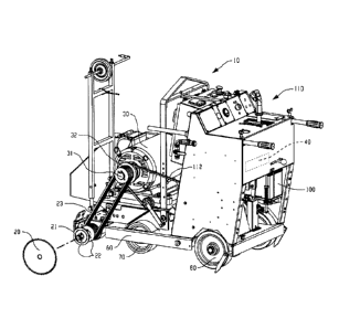
[0012] Figure 1 is a side perspective view of an electric concrete saw in
accordance with certain aspects of the present subject matter;
[0013] Figure 2 is a bottom perspective view of the electric concrete saw
shown
in Figure 1;
[0014] Figure 3 is a side schematic view of portions of the electric
concrete saw
shown in Figure 1;
[0015] Figure 4 is an enlarged perspective view of a second electric motor
and
tensioner assembly of an electric concrete saw in accordance with certain
aspects of
the present subject matter;
[0016] Figure 5 is an enlarged perspective cut-away view of a first and a
second
sheave assembly in accordance with certain aspects of the present subject
matter;
[0017] Figure 6 is an inline view of the cross sectional view shown in
Figure 5;
[0018] Figure 7 is an enlarged perspective view of the first and second
sheaves
shown in Figures 5 and 6 along with a transmission for an electric concrete
saw in
accordance with certain aspects of the present subject matter;
[0019] Figure 8 is a schematic diagram of an operating system for operating
an
electric concrete saw in accordance with certain aspects of the present
subject
matter; and,
[0020] Figures 9A-C are schematic wiring diagrams for an electric concrete
saw
in accordance with certain aspects of the present subject matter.
CA 02928879 2016-04-26
WO 2015/109247 PCT/U52015/011840
DETAILED DESCRIPTION OF THE EMBODIMENTS
[0021] The subject matter described herein provides an electric concrete
saw that
is configured for indoor cutting and which provides assistance to an operator
in
moving the saw without the need to connect the saw to an external power
supply.
[0022] In greater detail, and with reference to the drawings, wherein like
numerals refer to like parts throughout the several views, FIGS. 1-8
illustrate an
electric concrete saw 10 for modifying a material M including, but not limited
to,
cutting seams, notches and/or grooves into or through asphalt, concrete, stone
or
other similar materials according to the present disclosure. Concrete saw 10
includes an implement or blade 20 (shown schematically in Fig. 1) configured
for the
modifying of material M. The saw further includes a first electric motor 30
and a
second electric motor 40. First and second motors 30 and 40 are configured for
selectively driving a drive system 50 depending on an operational mode of saw
10.
Saw 10 has a frame 60 for supporting the first and second electric motors.
Further,
saw includes a front wheel assembly having a set of front wheels 70 and a rear
wheel assembly having a set of rear wheels 80. Front and/or rear assembly can
be
adjustable to change the cutting depth of blade 20. The saw is preferably a
self-
propelled saw, and thus at least one drive wheel is driven in a manner
described
below. In a preferred set of embodiments, rear wheels 80 are driven, which
will be
discussed in greater detail below. However, it will be appreciated that saw 10
could
also be a pushed without assistance from the self-propelled wheel(s).
[0023] Second electric motor 40 can be configured to also selectively drive
the
drive wheel, which in a preferred embodiment, is both rear wheels 80, and is
mechanically coupled to drive system 50. A speed regulator can be coupled to
second electric motor 40 so as to control the velocity of the output shaft of
the
second electric motor. Alternatively, the speed at which the drive wheel is
driven can
be controlled by a transmission. The speed regulator can also provide motor
driving
and control functions including starting and stopping control, torque
regulation,
phase control, voltage and current control. Second electric motor 40 is
operably
connected to one or more rechargeable batteries 100 and, as is well known,
converts the electricity from battery 100 to mechanical power in the form of
rotation
6
CA 02928879 2016-04-26
WO 2015/109247 PCT/US2015/011840
of a second output shaft 41 of second electric motor 40. Rechargeable battery
100 is
mounted relative to frame 60 in a suitable manner. Battery 100 can be a
conventional lead acid battery, a nickel-cadmium battery, a nickel metal
hydride
battery, a lithium battery, or a combination of conventional batteries. For
most
applications, battery 100 preferably comprises a 12 volt lead acid battery. In
use,
second electric motor 40 receives electric power from battery 100. In an
alternative
embodiment, second motor 40 could receive power from an external source of
power, such as an outlet. A controller 110 of saw 10 is in signal
communication with
first electric motor 30 and second electric motor 40 for controlling powering
and
speed of the motors. The controller is configured to monitor the status of the
battery
and when recharging is required the controller can actuate recharging of
battery 100
from power supplied by an external power supply 120. For example, when saw 10
is
connected to external power supply 120, such as a three-phase power supply of
at
least 300 volts, for powering first electric motor 30, controller 110 can with
proper
voltage control and rectification divert current from external power supply
120 to
battery 100 so the battery can be recharged. In an alternative embodiment,
second
motor 40 could receive power from power supply 120, directly or by way of
battery
100. In most cases the external power supply is a conventional 480 volt three-
phase
power source that is commonly found in the United States in commercial and
other
non-residential buildings.
[0024] Alternatively, battery 100 can be recharged by an external power
source
as further described below.
[0025] Specifically, it should be appreciated that that saw 10 can
optionally
include a charging system that supplies current to battery 100 to recharge the
battery. According to one aspect, the charging system can be an independent
plug-
in charging system with a plug connection for connecting by a cord to a
conventional
120 VAC wall plug of an external outlet. The plug-in charging system is
further
connected through a line to battery 100. The plug-in charging system may
include a
trickle charging mode for keeping the battery fresh when the saw is not in
use.
According to another aspect, the independent charging system can include a
solar
panel (not shown) mounted to saw 10 and electrically connected through a line
to
7
CA 02928879 2016-04-26
WO 2015/109247 PCT/US2015/011840
battery 100 and the solar panel could work in combination with the plug-in
charging
system . These charging systems can be used to keep the battery charged when,
for example, saw 10 is placed in storage or is otherwise not in use.
[0026] The operating system, schematically depicted in FIG. 8, for saw 10
preferably comprises a series operating modes. With these modes, saw 10 can
operate such that only one of first electric motor 30 and second electric
motor 40
drives drive system 50 at any given time. Thus, each of first electric motor
30 and
second electric motor 40 can be effectively de-coupled from drive system 50 so
that
the other of first motor 30 and second motor 40 powers the drive system.
[0027] As schematically illustrated in FIG. 8, the operating system of saw
10 also
includes operational systems such as a drive system 50 and a lift system 150
(primarily a hydraulic cylinder or ram for adjusting the cutting depth of
implement or
blade 20, which can include lifting the front of the saw). Drive system 50
preferably
drives rear wheels 80 supporting saw frame 60 at a desired speed in a forward
and/or rearward direction. Lift system 150 can tilt saw frame 60 to adjust the
cutting
or working depth of blade or implement 20. When adjusted, the saw blade may be
taken out of contact with substrate or material M being modified or cut.
Concrete
saw 10 can include an engine mounting system that minimizes vibration within
the
frame. The saw can also include at least one speed selection lever for
controlling the
speed of advancement of the saw. Additionally, saw 10 can include a dampening
mechanism that interrupts direct communication between first electric motor 30
and
saw blade 20 when the blade encounters significant predetermined resistance.
[0028] First electric motor 30 and second electric motor 40 are preferably
positioned in parallel relationship on frame 60 and are of a type generally
known in
the art. With this parallel relationship, each of first electric motor 30 and
second
electric motor 40 is oriented with its respective driven output shaft 31, 41
generally
parallel to one another and perpendicular to an axis defined by the length of
frame
60. This transverse arrangement aligns output shafts 31, 41 parallel to the
rotational
axis of an input shaft 53 of drive system 50, to afford an easy design for
interconnecting pulleys/sheaves between first electric motor 30 and drive
system 50,
and between second electric motor 40 and drive system 50. First shaft 31 and
8
CA 02928879 2016-04-26
WO 2015/109247 PCT/US2015/011840
second shaft 41 can have first and second pulleys 32, 42 respectfully attached
thereto. While shaft connecting or mounting systems are shown for several
components of this application, any output and/or input arrangement known in
the
art could be utilized for the components of this application.
[0029] Drive system 50 can a wide range of mechanisms known in the art,
which
includes, but is not limited to, a transmission 51, a gear mechanism 52, a
drive shaft
49 and/or a combination thereof, for transmitting and controlling rotational
energy
from first electric motor 30 and/or second electric motor 40 to drive the
driven
wheel(s), such as drive wheel 80. In an exemplary embodiment, drive system 50
includes input shaft 53, which is oriented substantially parallel with output
shafts 31,
41 and is for controlling and transmitting power to the driven wheel(s). As is
shown,
power is transmitted to rear wheels 80 of saw 10. A first sheave 54 and a
second
sheave 55 are operably connected to input shaft 53, wherein rotational output
from
one of the sheaves will rotate input shaft 53 and provide power to drive
system 50.
First sheave 54 is configured to be operably connected to first pulley 32 of
first
electric motor 30 by one or more V-belts 112, or other types of belts.
Thereby, first
electric motor 30 can drive input shaft 53 of drive system 50. Second sheave
55 is
configured to be operably connected to second pulley 42 of second electric
motor 40
by one or more V-belts 114, or other types of belts. Thereby, second electric
motor
40 can also drive input shaft 53 of drive system 50.
[0030] In one embodiment, first sheave 54 is connected to input shaft 53
through
a de-coupler 56 and second sheave 55 is connected to input shaft 53 whereby
that
rotation of second sheave 55 and rotation of input shaft 53 are integrally
linked, such
as by a direct connection for example. Through this arrangement, when second
electric motor 40 is used to rotate second sheave 55 on input shaft 53 in
order to
drive the drive system and power rear wheels 80, first sheave 54 will remain
in a
stationary rotational orientation, so that all power from the second motor is
transmitted to drive system 50. Further, when first electric motor 30 is used
to rotate
first sheave 54 on input shaft 53 in order to drive the drive system and power
rear
wheels 80, second sheave 55 remains stationary, and thus no power is lost in
driving second electric motor 40.
9
CA 02928879 2016-04-26
WO 2015/109247 PCT/US2015/011840
[0031] In this
configuration, second electric motor 40 can be relatively small,
because it is used only to power drive system 50 and is not used to power the
saw
blade, the hydraulic system, or the lift system. In one embodiment, second
electric
motor 40 is a direct current motor rated from about 1/5 HP (horsepower) up to
about
3 HP, and/or from about 12 volts to about 180 volts. In one embodiment, the
second
electric motor is 12 volt direct current motor rated at about 2 HP. Yet
further, first
sheave 54 has a first operating diameter 116 and second sheave 55 has a second
operating diameter 118 that affect the overall gear ratio of the drive system.
In one
set of embodiments, second diameter 118 is larger than first diameter 116 to
help
allow for the differences between motor 30 and motor 40. In one set of
embodiments, second diameter 118 is at least 50 percent larger than first
diameter
116. In another set of embodiments, second diameter 118 is at least 75 percent
larger than first diameter 116. In yet another set of embodiments, second
diameter
118 is about twice as big as first diameter 116.
[0032] De-coupler 56 can
be any de-coupling device known in the art. An
example of a de-coupler is a clutch bearing for use in the present invention
such as
a clutch bearing sold by McMaster-Carr Supply Co. of Aurora, Ohio that is
referenced to as a "High-Precision One-Way Locking Ball Bearing." It will be
appreciated that in addition to the illustrated clutch bearing, other systems
can be
used to allow selective driving of the first and second electric motors. For
example,
de-coupler 56 can include on or more conventional frictional clutch
assemblies.
Further, gears and shafts could be used to selectively de-couple or isolate
the first
and/or second electric motors from the drive system. Yet further, while de-
coupler
56 is shown within sheave 54, de-coupler could be within sheave 55 without
detracting from the invention of this application.
[0033] First electric
motor 30 when coupled to an external power supply is used
to power drive system 50, optionally hydraulic lift system 130, and saw blade
20, and
is therefore relatively large compared to second electric motor 40. In one
embodiment, first electric motor 30 is a three-phase alternating current
electric motor
rated from about 20 HP to about 50 HP and/or greater than 300 volts. In
another
aspect the first electric motor is rated from about 300 volts to about 500
volts, and is
CA 02928879 2016-04-26
WO 2015/109247 PCT/US2015/011840
preferably a 480 volt three phase AC motor intended to be coupled to a
conventional
480 volt three phase building outlet. In a preferred embodiment as shown
schematically in Fig. 8 saw 10 can include a third electric motor 140 for
driving
hydraulic system 130, and thus the first electric motor is then in not coupled
to
hydraulic system 130. The third electric motor is preferably a 12 volt direct
current
motor that is powered by battery 100.
[0034] Electric saw 10
also includes a blade shaft 21. The blade shaft or jack
shaft 21 is oriented parallel to first shaft 31 of the first electric motor
30, connected to
implement or saw blade 20, and supported by bearings mounted relative to frame
60. Blade shaft 21 includes at least one blade shaft pulley 22. First shaft 31
of first
electric motor 30 is operatively connected to blade shaft 21 by one or more V-
belts
23, or other type of belt, arranged to engage first pulley 32 to blade shaft
pulley 22
for rotating the blade.
[0035] Again, drive
system 50 can include transmission 51 and/or gear
mechanism 52 for transmitting mechanical power from rotation of input shaft 53
to
the drive wheel(s), which is shown to drive rear wheels 80 for powering the
rear
wheels as is well known. Preferably, transmission 51 comprises includes a
hydraulic
(hydrostatic) transmission available from sources such as Eaton and
Sundstrand. It
should also be appreciated that depicted transmission 51 is one example of a
transmission for electric saw 10 and that alternative
arrangements/configurations for
the transmission of saw 10 are contemplated. For example, in lieu of or in
combination with the belts, drive system 50 can be chain driven and can
include a
gear mechanism 52 to interconnect transmission 51 of drive system 50 to rear
wheels 80 of electric saw 10.
[0036] As indicated
above, drive system 50 can be selectively driven by first
electric motor 30 and/or second electric motor 40 depending on the power
supply
used. To allow for the selective motor drive, drive system 50 includes at
least one
de-coupler 56 discussed above. De-coupler 56 is
configured to selectively
decouple one of the motors from drive system 50 depending on the operational
mode of saw 10 (i.e., depending on whether first electric motor 30 or second
electric
motor 40 is driving rear wheels 80). In one set of embodiments, drive system
50
11
CA 02928879 2016-04-26
WO 2015/109247 PCT/LS2015/011840
includes de-coupler or clutch bearing assembly 56 operably associated with
first
sheave 54, which is operably associated with first electric motor 30. For
example, in
a second electric motor only mode, de-coupler 56 decouples first output shaft
31 of
first electric motor 30 from drive system 50, and in the first electric motor
only mode,
bearing 56 decouples second output shaft 41 of second electric motor 40 from
drive
system 50. Specifically, the clutch bearing only engages shaft 53 when sheave
54 is
rotated in one direction, and it allows sheave 54 to remain stationary when
sheave
55 is rotated in the same direction.
[0037] With reference back to FIG. 8, saw 10 includes a hydraulic system
130.
Hydraulic system 130 is operatively connected to lift system 150 and is in
signal
communication with controller 110. Hydraulic power for lift system 150 is
provided by
hydraulic system 130, which is preferably powered by third electric motor 140.
In that
these systems are known in the art, further details are not provided in the
interest of
brevity. Controller 110 is provided on saw 10 for controlling first, second
and third
electric motors 30, 40 and 140, and the hydraulic flow of hydraulic system 130
used
to power lift system 150. For example, third electric motor 140 can be used to
power
the hydraulic system and thus lift system 150 so that an operator can lift the
front of
saw 10 so that blade 20 can be lifted above and disengaged from a cutting
surface.
[0038] Any of the belts of this application can include tensioning devices
to
maintain a desired belt tension. For example, motor 40 and belt 114 can
include a
tensioner assembly 43 that includes a tensioner pulley 44 and tensioner arm
45.
Tensioner assemblies 43 provides for tension on the belt between second pulley
42
on second electric motor 40 and second sheave 55 on drive system 50.
Similarly,
motor 30 can include a tensioner assembly 33 that includes a tensioner pulley
34
and tensioner arm 35. Tensioner assemblies 33 provides for tension on the belt
between first pulley 32 on first electric motor 30 and first sheave 54 on
drive system
50.
[0039] Controller 110 can be mechanically and electrically connected to
first
electric motor 30 and second electric motor 40 associated with the driven
wheel that
is preferably the set of rear wheels 80 for controlling movement of saw 10.
12
CA 02928879 2016-04-26
WO 2015/109247 PCT/US2015/011840
[0040] Lift system 150 can operate as is known in the art. This system can
include a hydraulic cylinder (not shown) having one end that is secured in a
suitable
manner to frame 60 and having another end that has a pivotal connection to
front
wheels 70. A hydraulic pump (not shown) has a fluid connection to the cylinder
and
is rotationally driven by first electric motor 30 which has a power connection
to an
external power supply 120. Controller 110 mechanically and/or electrically
connected to, and is configured to control, the operation of first electric
motor 30,
third electric motor 140 and thus hydraulic system 130, and second electric
motor
40.
[0041] With reference to FIGs. 9A-C, shown are schematic wiring diagrams
for
saw 10 in accordance with certain embodiments of the present invention. In
addition, attached is a Second Wiring Diagram that also forms part of the
specification of this application.
[0042] It will be appreciated that variations of the above-disclosed
features and
functions, or alternatives thereof, and other features and functions may be
desirably
combined into many other different systems or applications. Also that various
presently unforeseen or unanticipated alternatives, modifications, variations
or
improvements therein may be subsequently made by those skilled in the art
which
are also intended to be encompassed by the following claims.
[0043] Many other benefits will no doubt become apparent from future
application
and development of this technology.
13