Note: Descriptions are shown in the official language in which they were submitted.
CA 02929010 2016-04-28
WO 2015/062846 PCT/EP2014/071749
10
DESCRIPTION
DEVICE FOR HVOF SPRAYING PROCESS
BACKGROUND OF THE INVENTION
The present invention relates to the technology of coating components,
especially
of metallic components used as hot gas parts in gas turbines. It refers to a
device
for High Velocity Oxygen Fuel (HVOF) thermal spraying process according to the
preamble of claim 1.
PRIOR ART
The use of gas turbines (GTs) for electrical power generation can be very
different
in their working modus. GTs can be either used in order to produce a constant
amount of electricity over a long period of time, as so-called "base loaders",
or
they can be used in order to level the differences between the electricity
production of rather constant sources (Nuclear, GT base loaders etc.) with
addition
of the variations due to the increasing amount of non-constant renewable
energy
CA 02929010 2016-04-28
WO 2015/062846 PCT/EP2014/071749
2
and due to the non-constant electricity demand. The second type of GT is a so-
called "cyclic/peaker".
Within the lifetime of a GT it is possible that a "loader" becomes a "peaker".
This
change in working conditions leads to differences in solicitations and
distress
modes (i.e. boundary conditions) for the components in the turbine and
especially
the ones subjected to extreme temperature conditions. In the case of "loaders"
they will need a larger creep and oxidation resistance, and in the case of
"peakers"
those component will need a better cycling resistance.
Furthermore, for each component, and locally on the component, the boundary
conditions are different. Some areas are more prone to fatigue and some other
areas to creep, oxidation/corrosion, erosion, etc. All those properties are
strongly
depending on a coating that is usually used to adapt the component to the
actual
operational boundary conditions. In order to answer the variations in
properties
needed it is therefore of strong interest to be able to produce coatings with
flexibly
and individually tailored properties.
The applicant of the present application has filed a so far not yet published
European patent application (Application number: 13160051). There is described
a
method for applying a coating system to a component of a turbo machine by use
of at least two separate powder feeders for each separate powder which can be
of
either homogeneous composition or a flexible composite powder, sprayed
simultaneously where the ratio of each powder can be changed online by
changing the feeding rate.
Protective metallic coatings for gas turbine components, for example of the
MCrAlY type (M = Fe, Ni, Co or combinations thereof) are applied by thermal
spraying, whereas the HVOF spraying process is one of the most frequently used
techniques for this purpose.
CA 02929010 2016-04-28
WO 2015/062846 PCT/EP2014/071749
3
It is known state of the art that HVOF systems run on either gas or liquid
fuels.
Liquid-fuelled HVOF systems have the advantage that they produce denser
coatings compared to their gas-fuelled counterparts. Therefore liquid-fuelled
HVOF systems are of more technical interest.
A typical HVOF system is schematically shown in Fig. 1. The system 1 comprises
a combustion chamber 2, where fuel 3 and oxygen 4 are fed in and combusted
into a complex gaseous mixture 5. Then this mixture 5 is forced through a
nozzle 6
(de-Laval section) which accelerates the gaseous mixture 5 to supersonic
velocity
within a barrel 7. Powder 8 for the coating is fed via a powder injector block
either
by a carrier gas into the combustion chamber 2 or downstream after the nozzle
6
into the barrel 7.
The known commercially available liquid fired HVOF burners work with only two
powder injectors. This implies limitations in deposition rate, sensitivity to
asymmetries in spray spot geometry (due to only C2 symmetry class), time
consuming retooling in case of e.g. application of double-layer coatings, etc.
HVOF burners using gaseous fuel usually work with single powder lines and
axial
injection into combustion chamber. In fact, these HVOF burners e.g. have a
more
stable spray spot geometry, but are not suitable for the application of
metallic
powder of the MCrAlY type due to the strong formation of oxides in the coating
layer.
The current design of the commercially available HVOF burner's powder injector
block comprises a bulk design and is manufactured in one piece. At a certain
level
of unavoidable abrasive wears in the hot gas section of the injector block
(that is
caused during radial injection of the powder into the supersonic gas), the
part has
to be replaced or elaborately reworked. The latter is only once possible and
has to
be done by the manufacturer of the original powder injector block. This is
expensive.
CA 02929010 2016-04-28
WO 2015/062846 PCT/EP2014/071749
4
There is no commercially design known that would allow for exchange of just
the
degraded section of the injector block. In addition, there is no design
improvement
commercially available, even if the current design shows significant losses
due to
shocks in gas flow that are caused by non-optimized design, for example at any
sudden transition in cross-section (phases and edges).
In EP 1 816 229 Al a spraying device for HVOF is disclosed, which comprises
only one powder injection line, furthermore a workpiece holder rotatable about
an
axis (A), a spay nozzle spraying in a spraying direction (S), wherein an angle
is
between (A) and (S), and a pivoting arrangement for pivoting the rotation axis
(A).
All regions of the circumferential surface surrounding the axis of rotation
(a) face
the spraying direction (S) once. With this device a good spray quality could
be
reached, but there is on one hand still a lot of time necessary for the
coating
process and on the other hand it is not possible to produce coatings with
flexibly
and individually tailored properties.
It would therefore be of great advantage to have an improved HVOF
system/device which allows a time reduction of the spraying process compared
to
the known state of the art systems as well as an improved maintainability, an
improved process robustness and flexibility/capability. An additional
advantage is
when at the same time compatibility to the existing spraying equipment could
be
preserved.
SUMMARY OF THE INVENTION
It is an object of the present invention to provide a HVOF device for coating
a
component of a turbo machine, which allows a time reduction of the spraying
process compared to the known state of the art systems as well as an improved
maintainability, an improved process robustness and flexibility/capability. At
the
same time compatibility to the existing spraying equipment should be
preserved.
CA 02929010 2016-04-28
WO 2015/062846 PCT/EP2014/071749
These and other objects are obtained by a HVOF device according to independent
claim 1.
The core of the invention is that the powder injector block of the HVOF device
5 according to the preamble of claim 1 comprises on one hand at least four
powder
injectors arranged in an equal circumferential distance around the axis (A)
and one
the other hand an exchangeable hot gas section insert inside the powder
injector
block designed as a cylindrical bush with at least four openings said openings
arranged in an equal circumferential distance around the axis (A) in the
cylinder,
wherein the bush is fixed by the at least four powder injectors extending
through
said openings.
As an advantage, the hot gas section insert can be exchanged after unavoidable
wear in a fast way without a lot of costs and without elaborately reworking.
According to the known state of the art there are commonly used two powder
injection lines for liquid fuel fired HVOF thermal spraying systems. But it
was
identified that the maximum deposition rate during the coating process is
limited by
the capacity of the powder lines. When the maximum powder flow rate is reached
the powder flow and with this also the flame start to pulsate and the coating
process becomes instable. By using additional powder injectors (in minimum
four
powder injectors) which are arranged in a symmetrical way with an equal
distance
between each other according to the present application higher deposition
rates
under stable coating conditions could be reached. The spray spot geometry will
become much more stable.
An additional important advantage of the present application is that the
claimed
hardware improvements (exchangeable gas section insert, at least four powder
injectors) could be reversible implemented within a limited time into already
existing devices/systems. Only alignments/modifications with respect to the
machine speed/number of repetitions and the control of the powder lines are
necessary. All other additional process parameter, like combustion chamber
CA 02929010 2016-04-28
WO 2015/062846 PCT/EP2014/071749
6
pressure, kerosine flow, oxygen flow, spraying distance, robot programs etc.
have
not to be changed because of the maintenance/preservation of the spray spot
geometry.
According to an embodiment of the inventive device the cylindrical bush
comprises
a guiding groove for a definite orientation of said bush around the axis A,
wherein
the bush is inserted from the outside of the powder injector block.
Another embodiment of the invention is characterized in that in addition to
the
above-mentioned features of the powder injector block the de-Laval section has
a
bell-shaped design or at least a design with rounding out of edges. Without
those
latter mentioned improvements the current commercially available design shows
significant losses due to shocks in gas flow. Shocks and therefore
thermodynamic
losses for standard setup could be clearly demonstrated by means of CFD
(Computational Fluid Dynamic) simulations at any sudden transition in cross-
section (phases and edges).
The bell-shaped de-Laval section can be combined with a cylindrical barrel. In
this
option, the gas reaches already the final velocity before entering the powder
injector block. No further expansion is needed.
It is further possible that the bell-shaped design of the de-Laval section is
combined with a full conical design of the powder injector block / barrel
section.
As an advantage the claimed device is used for HVOF coating of gas turbine
components, especially for applying metallic protective coatings of the MCrAlY
type.
CA 02929010 2016-04-28
WO 2015/062846 PCT/EP2014/071749
7
BRIEF DESCRIPTION OF THE DRAWINGS
The present invention is now to be explained more closely by means of
different
embodiments and with reference to the attached drawings.
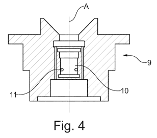
Fig. 1 shows in a simplified drawing a configuration for a HVOF
thermal
spraying device according to the prior art;
Fig. 2 shows a photo of the powder injector block according to the
prior
art with two powder injectors;
Fig. 3 shows a photo of the powder injector block according to the
invention with four powder injectors;
Fig. 4 shows a schematic cut through the injector block according to a
first embodiment of the invention;
Fig. 5 shows a photo of the exchangeable hot gas section device
(cylindrical bush) according to an embodiment of the invention and
Fig. 6, 7, 8 show in simplified drawings three embodiments of the de-
Laval
section and the barrel of the device.
DETAILED DESCRIPTION OF DIFFERENT EMBODIMENTS OF THE
INVENTION
The invention uses state of the art and commercially available liquid fuel
fired
HVOF equipment as basis and implements several improvements regarding
process stability/capabilities/maintainability. At the same time,
compatibility to the
existing spraying equipment is preserved.
CA 02929010 2016-04-28
WO 2015/062846 PCT/EP2014/071749
8
A first feature is the application of additional powder injectors to the
injector block
that enables the reliable processing of higher powder feed rates, which leads
to
time reduction, stabilizes the spray spot geometry due to a symmetry increase
and
enables the simultaneous processing of different powder types with or without
time
consuming retooling.
This feature is shown in Fig. 3 compared to Fig. 2. Fig. 2 is a photo of the
standard
powder injector block 9 according to the prior art. The two powder injectors 8
are
clearly visible. Fig. 3 is a photo of the powder injector block 9 according to
the
invention with four powder injectors 8. The powder injectors 8 are
symmetrically
arranged in circumferential direction that means in an equal circumferential
distance around the axis A (A is not shown in Fig. 3).
A second feature of the device according to the present invention is the
arrangement of an exchangeable insert 10 into the flow section of the injector
block 9 in order to reduce maintenance costs and to improve the
maintainability of
the HVOF burner's injector block 9. Fig. 5 shows a photo of that insert in
form of a
cylindrical bush 10 with openings 11 and a guiding groove 12, while Fig. 4
shows a
schematic cut through the injector block 9. The openings 11 (here four) are
arranged in an equal circumferential distance around the axis A (see Fig. 4)
in the
cylinder. The four powder injectors 8 extend through the openings 11 and fix
the
bush 10 in the powder injector block 9. The guiding groove 12 is the warrantor
for
a definite orientation of said bush 10 around the axis A. The bush 10 is
inserted
from the outside of the powder injector block 9 and can be exchanged in an
easy
way when it is necessary because of wear.
Such a prototype of a modified HVOF injector block 9 having four powder
injectors
8 and an exchangeable hot gas section insert 10 was tested at an existing
spraying booth of the applicant. For coating a gas turbine blade for a GT of
the
applicant, the deposition rate could be doubled at remaining coating quality
(bonding, coating thickness distribution, porosity) resulting in about 40%
lead time
reduction with respect to coating the blade with a commercially available HVOF
injector block. The spray spot of the modified HVOF device was found to be
highly
CA 02929010 2016-04-28
WO 2015/062846 PCT/EP2014/071749
9
symmetric (round) even without special adjustment of carrier gas flows as
usually
needed for the standard setup.
The following advantages could be reached:
The modified injector block was implemented into the existing equipment within
few minutes, uses the standard parameter set as well as the standard robot
program (solely the amount of repetitions has needed adjustment) and obtains
the
same deposition efficiency when compared to the standard setup. The flame
(i.e.
amount/distance of diamond shocks) was found to be the same for standard as
well as modified injector block.
There is only a low risk for residual stresses caused crack formation in the
coating
at critical locations of the components due to the increases deposition rate.
The
implementation is not complicated. Besides possible additional powder feeders,
the presented hardware modifications do not require adaption of existing
spraying
equipment / setup, i.e. use of the same controller/robot program/fuel/ gas
etc.
Of course the invention is not limited to the described embodiment, for
example
more than four powder injectors could be used.
In addition, CFD investigations have demonstrated the potential for design
improvement of the commercial available baseline equipment with respect to
losses by thermodynamic shocks. The de- Laval section 4 of the device 1 can be
improved by several options, which are described as the following embodiments:
1. Removal of steps and phases in current baseline design by rounding out of
edges. This option does not need time consuming CFD investigations and
attenuates the thermodynamic losses by shocks resulting in slightly increased
particle velocities and lower coating porosity, respectively (see Fig. 6).
CA 02929010 2016-04-28
WO 2015/062846
PCT/EP2014/071749
2. Bell-shaped design of the de-Laval section 4 in combination with a
cylindrical
barrel 7. In this option, the gas reaches already the final velocity before
entering
the powder injector block 9. No further expansion is needed and the powder
injection 8/ barrel section 7 is designed cylindrically without edges and
phases.
5 The improved layout removes also the significant overexpansion at barrel
7 exit of
the baseline. Less shocks and thermodynamic losses result in higher particle
velocitiy and lower coating porosity, respectively (see Fig. 7).
3. Bell-shaped design of the de-Laval section 4 in combination with a full
conical
10 design of the powder injector block 9 / barrel section 7. The improved
layout
removes also the significant overexpansion at barrel 7 exit of the baseline.
The device according to the invention is preferably used for coating gas
turbine
components with metallic protective coatings of the MCrAlY type.
LIST OF REFERENCE NUMERALS
1 HVOF device
2 combustion chamber
3 fuel
4 oxygen
5 gaseous mixture, combustion gas
6 nozzle, de-Laval section
7 barrel
8 powder injector
9 powder injector block
10 hot gas section insert, cylindrical bush
11 opening
12 guiding groove