Note: Descriptions are shown in the official language in which they were submitted.
MULTIPLE BIT HAND TOOL
CROSS-REFERENCE TO RELATED APPLICATIONS
[0001] This application claims the benefit of priority of U.S. Provisional
Patent Application
No. 61/896,501 filed October 28, 2013.
FIELD
[0002] The present application relates generally to hand tools. More
particularly, the present
disclosure relates to a multiple bit (multi-bit) hand tool.
BACKGROUND
[0003] The use of hand tools has been around for many generations. Over the
years, these
hand tools have evolved to include different versions or updated versions of
previous
embodiments. For instance, hand tools, such as screwdrivers, are now available
as multiple bit,
or multi-bit, tools whereby one tool may be easily transformed into multiple
tools. In one
embodiment, a multi-bit tool may provide the functionality of six screwdrivers
of different size
and type.
[0004] Multi-bit tools are continually being improved in order to, not
only, facilitate use but
also to increase the longevity of the tool.
[0005] Therefore, there is provided a novel multiple bit hand tool.
SUMMARY
[0006] It is an aspect of the disclosure to provide a hand tool having a
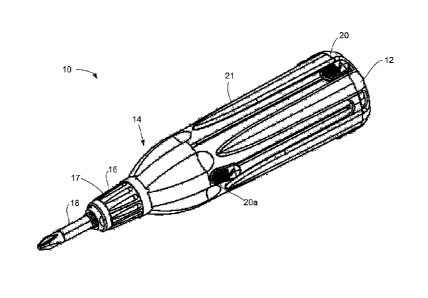
suitable means for
automatically locking the bits or tool elements in their operative position,
once extended to that
position, and a suitable means for readily unlocking the tool elements when
retraction is desired.
[0007] It is an aspect of the disclosure to provide a hand tool or
screwdriver of the general
type referred to above, but having a suitable means for automatically
extending or retracting tool
elements.
[0008] In a first aspect, the present disclosure provides a multiple bit
hand tool including a
handle body having a chuck, a plurality of tool elements housed within the
handle body and
extendable and retractable by an actuator, and a locking mechanism in the
chuck for locking
1
EDC_LA1M 2236367\1
CA 2929015 2020-04-03
CA 02929015 2016-04-28
WO 2015/061898 PCT/CA2014/051036
a selected one of the tool elements in an extended position, wherein the
locking mechanism
includes a latch for retaining the tool element in the extended position and a
release cam for
removing the latch from retaining the tool element wherein the release cam is
actuated by
the actuator.
[0009] In a second aspect, the present disclosure provides a multiple bit hand
tool
including a handle body and a plurality of tool elements housed within the
handle body and
extendable and retractable by an actuator having a spring driven mechanism,
wherein the
spring driven actuation mechanism is housed within the handle body and extends
and
retracts any one of the plurality of tool elements.
[0010] In another aspect, the present disclosure provides a multiple bit hand
tool including
a handle body having a chuck, a plurality of tool elements housed within the
handle body and
extendable and retractable by an actuator having a spring driven mechanism,
and a locking
mechanism in the chuck for locking a selected one of the tool elements in an
extended
position, wherein the locking mechanism includes a latch for retaining the
tool element in the
extended position and a release cam for removing the latch from retaining the
tool element,
wherein the release cam is actuated by the actuator and wherein the spring
driven actuation
mechanism is housed within the handle body and extends and retracts any one of
the
plurality of tool elements.
[0011] In an aspect, the present disclosure provides a multiple bit hand tool
as generally
and specifically described herein.
[0012] Other aspects and features of the present disclosure will become
apparent to those
ordinarily skilled in the art upon review of the following description of
specific embodiments in
conjunction with the accompanying figures.
BRIEF DESCRIPTION OF THE DRAWINGS
[0013] Embodiments of the present disclosure will now be described, by way of
example
only, with reference to the attached Figures.
[0014] Figure us a perspective view of a multiple bit hand tool, in accordance
with an
embodiment;
[0015] Figures 2A, 2B, and 2C are side, end, and perspective views,
respectively, of a
handle portion of the hand tool of Figure 1;
2
CA 02929015 2016-04-28
WO 2015/061898 PCT/CA2014/051036
[0016] Figures 3A, 3B, 3C, and 3D are side, inside end, front end, and
perspective views,
respectively, of a body portion of the hand tool of Figure 1;
[0017] Figure 4A is a schematic view of the handle portion and the body
portion partially
connected;
[0018] Figure 4B is an enlarged view of a cap end of the handle portion;
[0019] Figures 5A, 5B, and 5C are perspective, assembly, and cross-section
views,
respectively, of an actuator mechanism;
[0020] Figures 6A, 6B, 6C, and 6D are side, front end, inside end, and
assembly views,
respectively, of a latch portion;
[0021] Figures 7A, 7B, and 7C are inside end, front end, and side views,
respectively, of a
bit end cap;
[0022] Figure 8 is a cross section view of a locking mechanism;
[0023] Figure 9 is a cross-section view of a spring driven actuation mechanism
for a
multiple bit hand tool in a retracted position;
[0024] Figure 10 is a cross-section view of the spring driven actuation
mechanism of
Figure 9 in an intermediate position;
[0025] Figure 11 is a cross-section view of the spring driven actuation
mechanism of
Figure 9 in an extended position; and
[0026] Figure 12 is a cross-section view showing drive springs of the spring
driven
actuation mechanism of Figure 9.
DETAILED DESCRIPTION
[0027] Generally, the present disclosure provides a multiple bit (multi-bit)
hand tool. The
multi-bit hand tool includes a handle portion and a body portion which are in
a friction-fit
relationship which reduces the number of parts necessary to manufacture the
multi-bit hand
tool. In another embodiment, the multi-bit tool includes a locking collar
which includes an
improved locking mechanism to hold a tool in place when in use. These will be
described in
more detail below.
[0028] Turning to Figure 1, a perspective view of a multi-bit hand tool is
shown. The multi-
bit hand tool 10 includes a handle portion 12 and a body portion 14. The body
portion 14
includes a chuck, or chuck portion, 16 which includes an opening allowing one
of a set of tool
elements or bits 18 (typically housed within the tool 10) to be extended out
of the tool 10 for
3
CA 02929015 2016-04-28
WO 2015/061898 PCT/CA2014/051036
use. The tool bit 18 is locked in place by a locking collar 17 which is part
of the chuck portion
16. The set of tool elements or bits 18 are generally housed within the tool
10 until one of
the set of tool bits 18 is actuated via an actuating mechanism 20 to extend
the tool bit 18
through the chuck portion 16. When the body portion 14 is connected to the
handle portion
12 (as described in more detail below), a set of slots 21 for receiving the
actuating
mechanism 20 is created within which individual actuating mechanisms 20 may
slide causing
the tool bit 18 to both be extended through the chuck portion and also
retracted from the
chuck portion 16.
[0029] As shown in Figure 1, one of the tool bits 18 is extended through the
chuck via the
actuating mechanism 20a.
[0030] Turning to Figures 2A to 2C, a side view, an end view and a perspective
view of the
handle portion 12 is shown. As more clearly shown in these Figures, the handle
portion 12
includes a cap portion 25 which serves as a cover for one end of the tool,
namely the end
away from the chuck portion 16. Extending out from the cap portion 25 are a
plurality of slats
28 extend therefrom. Individual prongs 29 which serve as support are also
mounted to the
cap portion 25 and extend away from the cap portion 25. Each slat 28 includes
a groove 26
on either side of the slat 28 to receive corresponding protrusions or tongues
which are part of
the body portion 14 to provide a friction fit handle for the tool 10.
[0031] Turning to Figures 3A to 3D, a side view, an end view, a front view and
a
perspective view of a first embodiment of a body portion 14 is shown. As
discussed above,
the body portion 14 includes a chuck portion 16 over which the locking collar
17 is placed to
assist in locking the tool bit (not shown) when the tool bit is extended
through the chuck. In
the current embodiment, it is preferred that the chuck portion is formed as an
integral part of
the body portion 14, however, it may also be a separate piece. The body
portion 14 further
includes a central opening 32 within the chuck portion 16 for receiving the
tool bit 18 when it
is extended through the chuck portion 16 as selected or actuated by a user. As
will be
understood, the tool bit 18 is also retracted through the same central opening
32 after the
user is finished using the tool bit. In use, the chuck portion 16 reduces or
prevents rotation of
the tool bits by virtue of its central opening 32 and/or the chuck portion 16
having a cross-
section (hexagonal for example) corresponding dimensionally to a cross-section
of the tool
bit 18. The locking collar 17 also contributes to this reduction of rotation.
4
CA 02929015 2016-04-28
WO 2015/061898 PCT/CA2014/051036
[0032] The body portion 14 further includes a set of flanges 22 extending away
from the
locking collar 17. The flanges 22 include protrusions or a tongue portion 23
for mating with
the grooves in the handle portion 12. More specifically, in a preferred
embodiment, a pair of
flanges 22 fit between two slats of the handle portion and are slidably
connected and in a
friction fit relationship with the slats thereby providing the slot in which
the actuating
mechanism slides and a friction-fit handle.
[0033] Turning to Figure 4A, a perspective view of the handle portion 12 and
the body
portion 14 in partial connection is shown. As shown, a pair of flanges 22 of
the body portion
14 fit between two slats 28 of the handle portion 12 and provide the slot 21
therebetween the
two flanges 22 within which the actuation mechanism (not shown) resides and
slides. As
discussed above, protrusions on the surface of the flanges 22 mate with
grooves within the
slats 28 in order to provide a friction fit between the body portion 14 and
the handle portion
12. In an alternative embodiment, the protrusions may be a part of the handle
portion 12
while the grooves are part of the body portion 16. In either embodiment, the
connection
between the protrusions and the grooves provides for a friction fit handle and
body for the
hand tool 10. Although not shown in Figures 4A and 4B, an individual actuating
mechanism
(as more clearly shown in Figure 5) for each tool bit is located in each slot
created between
the two flanges 22 and the pair of slats 28. When fitted together, the body
portion 14 and the
handle portion 12 may also form a container for housing components of the tool
10 such as,
but not limited to tool bits 18.
[0034] Figure 4B is an enlarged view of an end of the handle portion. As
shown, the cap
portion 25 provides a base for the handle portion 12 and the connection
between the flanges
22 and the slats 28 is shown in more detail.
[0035] Turning to Figures 5A to 5c, various views of an actuation member 20
including a
tool bit 18 are provided. Figure 5a is a perspective view of the actuation
member and the
tool bit connected, Figure 5b is a perspective view of the actuation member
and the tool bit
disconnected and Figure 5c is an enlarged view of a joint within the actuation
member.
[0036] The actuation member includes an arm portion 37 and a tool bit portion
39. The
tool bit portion includes a bit end cap 44 which houses the tool bit 18. The
arm portion 37
includes an actuator button 36 at one end, a connecting rod 38 and a release
cam 40
connected to a set, preferably a pair, of release cam arms 42.
CA 02929015 2016-04-28
WO 2015/061898
PCT/CA2014/051036
[0037] As more clearly shown in Figure 5C, the release cam 40 is attached to
the bit end
cap 44 which serves, in some manners, as an extension of the tool bit 18. The
bit end cap
44 is preferably moulded such that the tool bit 18 is firmly fitted within the
bit end cap 44.
The tool bit 18 located within a bit end cap 44 which includes a cavity
portion 46 which
receives the release cam arms 42 when connected. The release cam arms 42 each
include
a tab 43 to provide protection from the release cam arms 42 accidently
releasing from the bit
end cap 44. As will be understood, in order to release the arm portion 37 from
the bit portion
39, one would have to press the release arms 42 towards each other to ensure
that the tabs
43 can pass by an opening 45 at the end of the bit end cap 44.
[0038] The connection between the release cam arms 42 and the cavity 46 allows
for
movement of the connecting rod 38 with respect to the tool bit 18 and vice
versa. This
movement assists in allowing the tool bit 18 to be extended through and
retracted from the
chuck. The release cam 40 assists in translating the pressure applied to the
actuation button
into a force to either extend or retract the tool bit.
[0039] In
operation, when a user applies a pressure to the actuator button 36, the
button
slides along the associated slot 21. By applying this pressure, a user may
extend the tool bit
out for use or may retract the tool bit for storage.
[0040] The joint produced by the connection between the cam and the bit cap
end provides
the necessary flexibility for the actuation mechanism to move along the slot
(as described
below).
[0041] Turning to Figures 6A to 6C, various views of a latch portion for use
with the locking
collar are shown. Figure 6a is a side view of the latch portion, Figure 6B is
a top view and
Figure 6C is a bottom view. Figure 6D is perspective view of the latch mating
with the
locking collar.
[0042] As shown in Figure 6A, the latch portion 100 includes a set of latch
arms 50, which
in the present embodiment is three (3), that are flexible and biased inward.
Each latch arm
50 has a bit end cap contact 52 and a release cam contact 54 for initiating
and enabling
retraction of the tool bit when required or requested by the user. When the
tool bit is in the
extended position, the bit end cap contact 52 engages the bit end cap 44 at a
position A (as
shown in Figure 8) and the cam contact engages the release cam 40 at a
position B (as
shown in Figure 8). As the tool bit passes by the latch portion when being
either extended or
retracted, the arms 50 pivot slightly about their connection 58 to a cap
portion 60 of the latch
6
CA 02929015 2016-04-28
WO 2015/061898 PCT/CA2014/051036
portion. Further details of the latch portion of the locking collar are shown
in Figures 6b and
6c.
[0043] As shown in Figure 60, when the latch portion is attached to the
locking collar, the
arms fit within apertures in the locking collar and are preferably snapped
into place. This is
shown in more detail in Figure 8.
[0044] As shown in Figure 8, which is a cut away view of the chuck portion
with a tool bit in
the extended position, in order to lock the tool bit in place after it has
been extended out of
the chuck portion, (or past the lower end of the latch portion 100), there is
contact at points A
and B between the latch portion 100 and the bit end cap 44 which reduce the
likelihood or
prevent the tool bit from being retracted unless pressure is placed on the
actuating
mechanism. This provides protection against the accidental retraction of the
tool bit,
especially during use. As shown, in the extend position, the release cam is
ushered forward
by the pressure applied to the actuation mechanism (when moving the actuation
mechanism
20 from the cap portion 25 towards the chuck portion 16) and the release arms
42 provide a
force to extend the tool bit forward. The bit end cap 44 acts as a stop to the
cam release so
that the tool bit is not extended too far out of the chuck.
[0045] Each tool element 18 connects a bit to the actuating mechanism 20 with
a bit end
cap 44. The bit end cap 44 has a bit end cap cavity 46 at its proximal end.
The bit end cap
44 is slidably connected to the actuating mechanism 20 via the connecting rod
38. The
connecting rod 38 has a release cam 40 for engaging with the bit end cap 44.
The release
cam 40 includes release cam arms 42 which are inserted into and slidably
engage with the
bit end cap cavity 46 and the release cam arms 42 slidably move into and out
of the bit end
cap cavity 46. The release cam arms 42 remain within the bit end cap cavity 46
by retaining
elements 60 at the ends of the release cam arms 42. The bit end cap 44 is
retained in the
locking collar 17 by the latch portion 100.
[0046] In operation, when the tool element or bit 18 is being extended, the
user pushes the
actuator button 36 of the actuating mechanism 20 forward. As will be
understood, the
pressure applied to the button causes the tool bit 18 to slide internally into
the chuck portion
16 and then extend out through the opening or aperture 36. A front surface of
the release
cam 40 (and/or the release cam arms 42) contacts on a back surface of the bit
end cap 44 to
slide the tool bit 18 into the opening. Once the tool element 18 is extended,
the latch arms
50, at point A, contact the bit end cap 44 and protect against retraction of
the tool bit 18. In
7
[0047] The latch arms 50 have a latch angled surface which corresponds to a
chuck angled
surface 137 on a surface of the chuck 16. When there is a rearward axial force
applied on the
tool bit 18, the force is transmitted through the bit end cap 44 and onto the
latch arm 50, pushing
the latch angled surface onto the chuck angled surface 137, and thereby
causing the latch arm
50 to move inward towards and tightening the contact with the bit end cap 44
and release cam
40.
[0048] To retract the tool bit 18, the release cam 40 is slid rearward
within the back of the bit
end cap 44, by pressing rearwardly on the actuator button 36. The rearward
movement of the
actuator button 36 pulls the connecting rod 38 and the release cam 40
rearward. The rearward
movement of the release cam 40 pushes the latch portion 100 outward at B
thereby removing the
contact at point A and allowing the bit end cap 44 and tool element 18 to
retract into the handle
portion 12. The travel length of the release cam arms 42 within the bit end
cap cavity 46 is such
that the back surface B of the release cam 40 pushes the latch arms 50
radially out enough to
remove the contact at A.
[0049] The too bit 18 and the bit end cap 44 may be integrally formed,
however, where the
bit 18 and the bit end cap 44 are separate components, they are in a torque
transmitting
relationship. For example, the bit may include a keyed notch which corresponds
to a keyed slot
of the bit end cap 44. The bit end cap 44 may be, for example, pressed on or
over-molded to the
bit 18.
[0050] The bit end cap 44 may have grooves/guides 62 such that when the
actuator button 36
pushes the connecting rod 38 forward the bit end cap 44 is guided by
corresponding
grooves/guides on the inner surface of the latch portion 100 into the central
opening 36.
[0051] The release cam arms 42 may be flexibly biased away from each other
such that when
the release cam arms 42 are inserted into the bit end cap cavity 46 the
release cam arms 42 flex
enough to get through the opening in the bit end cap cavity 46. Once the
release cam arms 42
are in the bit end cap cavity 38, the release cam arms 42 are retained by in
the bit end cap cavity
38.
[0052] In the current disclosure, an advantage of the disclosure is that
the multiple bit hand
tool 10 may simplify the number and type of component parts thereby reducing
cost. The multiple
bit hand tool 10 may have a simplified manufacture and assembly and a
reduction or
8
CA 2929015 2020-04-03
CA 02929015 2016-04-28
WO 2015/061898 PCT/CA2014/051036
elimination of mechanical fasteners (e.g., threaded fasteners). Another
advantage is that
the locking collar may allow for one handed extension and retraction with a
hands-free chuck
based locking collar.
[0053] The multiple bit hand tool 10 may also be able to house longer tool
bits 18 as the
components of the actuating mechanism 20 may be more compact in length. Longer
tool
bits 18 may provide a user with access to increased hole depth. Alternatively,
the handle
body 12 may be shortened as the components of the actuating mechanism 20
providing a
compact multiple bit hand tool 10.
[0054] As will be understood, Figures 1-8 illustrate one way in which the
locking collar
could be installed. This disclosure is not limited to this specific
configuration.
[0055] Figures 9 to 12 are multiple cut-away views of another embodiment of a
handle
portion of a multiple bit hand tool. In the current embodiment, the multiple
bit hand tool 200
includes a spring driven actuation mechanism 202. Figures 9 to 11 illustrate a
center cross
sectional view having the chuck end removed for ease of viewing while Figure
12 illustrates a
further cross sectional view having a chuck end and extended bit removed. The
figures
reflect the motion and operation of an actuating mechanism 20 when a tool bit
is being
extended through the chuck for use.
[0056] The spring driven actuation mechanism 202 is housed centrally along a
rotation
axis within a handle body 204. The handle body 204 includes an end cap 205 for
allowing
for insertion and assembly of the spring driven actuation mechanism 202. The
single spring
driven actuation mechanism drives any and each of a plurality of tool elements
206, one at a
time, to an extended/in-use position and back to a retracted/storage position.
The spring
driven actuation mechanism 202 may drive any of the plurality of the tool
elements 206, and
preferably all of the tool elements 206 of the multiple bit hand tool 200. The
spring driven
actuation mechanism 202 is able to extend and retract the tool elements 206
without having
to manually extend the tool elements 206 and translates a small movement of an
actuator
button 208 into a much larger movement of the tool element 206 associated with
that
actuator button 208, whether that movement is extension or retraction.
[0057] To extend the tool element 206, a user actuates (e.g., slides, presses,
or switches)
the actuator button 208 to engage a connecting rod 210 with the spring driven
actuation
mechanism 202. The spring driven actuation mechanism 202 drives the connecting
rod 210
forward associated with a tool element 206 into the extended position.
9
CA 02929015 2016-04-28
WO 2015/061898 PCT/CA2014/051036
[0058] To retract the tool element 206, the user actuates (e.g., slides,
presses, or
switches) the actuator button 208 to pull the connecting rod 210 and tool
element rearward
206. Once the tool element 206 is retracted, the spring driven actuation
mechanism 202
disengages from the connecting rod 210 of that particular tool element 206.
The spring
driven actuation mechanism 202 may then be engaged by any one of the tool
elements 206
selected by the user.
[0059] Beginning from a retracted position (Figure 9), for extension, a user
pushes the
actuator button 208 forward for a selected one of the tool elements 206. The
actuator button
208 pulls forward a channel guide 212 which removes the connecting rod 210
from an
actuator rest 214. The channel guide 212 rides on runners 213 on an inner
surface of the
body 204. The channel guide 212 urges the connecting rod 210 off of a rest pin
216 of the
actuator rest 214 and into a cavity 218 of a spring collar 220. The connecting
rod 210 for the
selected tool element 206 is now engaged with the spring collar 220 and in an
intermediate
position as schematically shown in Figure 10.
[0060] Wth the same actuation of the actuator button 208, the channel guide
212 pushes
an actuator lockout 222 forward. The actuator lockout is attached (e.g., by
fastener 223) to
an internal shaft 224 to slide the internal shaft 224 forward. The internal
shaft 224 slides
inside an external shaft 226 (having two components 226A, 226B shown in Figure
12) to
push a distal spring connector 227 and stretch a drive spring 228. The drive
spring or
springs 228 (e.g., a helical extension spring) is loaded in tension providing
a pull force,
opposing extension. A proximal end of the drive spring 228 is attached to a
proximal spring
connector 229 and the distal end of the drive spring 228 is attached to the
distal spring
connector 227. The distal spring connector 227 slides with respect to the
internal shaft 224
within the external shaft 226 and, in the extended position, contacts the
spring collar 220.
The proximal spring connector 229 slides with respect to the internal shaft
224 and, in the
retracted and intermediate positions, contacts the spring collar 220.
[0061] A first tapered section 230 on the internal shaft 224 releases a
retract leaf spring
232. The retract leaf spring is attached to the external shaft 226 and is
biased outward. The
retract leaf spring 232 is released from contacting the spring collar 220. The
drive spring 228
then pulls the proximal spring connector 229 and the spring collar 220 is
launched forward.
The spring collar 220 slides freely on an outer surface of the external shaft
226 to propel the
tool element 206 to the extended position (Figure 11). In the extended
position, an extended
CA 02929015 2016-04-28
WO 2015/061898 PCT/CA2014/051036
leaf spring 234, biased outward and attached to the external shaft 226, holds
the spring
collar 220 in place. The tool element 206 passes through an opening in the
chuck (not
shown) and is now in the extended and in use position.
[0062] In the extended position the actuator lockout 222 stops non-selected
tool elements
206 from being actuated by blocking the channel guides 212 of non-selected
actuator
buttons 208.
[0063] The tool element 206 may be locked in the extended position by the
extend leaf
spring 234 or with another locking mechanism such as the locking collar 17 of
Figures 1 to 8.
[0064] For retraction, a user pushes the actuator button 208 rearward. The
actuator button
208 pulls the actuator lockout 222, internal shaft 224, and proximal spring
connector 229
rearwardly stretching and pulling the drive spring 228. A second tapered
section 236 on the
internal shaft 224 releases the extend leaf spring 234 from contacting the
spring collar 220.
The drive spring 228 then pulls the distal spring connector 227 to propel the
spring collar 220
rearward to the intermediate position (Figure 10) where the retract leaf
spring 232 holds the
spring collar 220 in place. The connecting rod 210 is urged by the channel
guide 212 out of
the cavity 218 of the spring collar 220 and onto the rest pin 216 of the
actuator rest 214. The
tool element 206 is then back in the retracted and stored position (Figure 9).
[0065] Where there is one spring actuation mechanism 202 for multiple tool
elements 206
there may be a reduction of components. Less moving parts and springs may lead
to a
simplified manufacture and assembly and a longer life of the hand tool 200. As
the spring
actuation mechanism 202 is a central mechanism with an actuator lockout 222,
only one tool
element 206 is selectable at a time which may reduce jamming.
[0066] Figures 9 to 12 illustrate one way in which the spring driven actuation
mechanism
could be installed. The disclosure is not limited to this specific
configuration. One particular
possible variation is that the spring driven actuation mechanism.
[0067] In an embodiment, the spring driven actuation mechanism 202 may be used
in
place of the actuating mechanism 20 of the multiple bit hand tool 10 of Figure
1 such that the
multiple bit hand tool 10 has both the release cam 40 and locking collar 17 as
described with
reference to Figures 1 to 8 and the spring driven actuation mechanism 202 as
described with
reference to Figures 9 to 12. In this case, the locking collar 17 is in the
chuck and does not
interfere with the operation of the spring driven actuator 202 thus providing
a central spring
driven actuation mechanism with a hands-free chuck based locking collar. The
locking collar
11
CA 02929015 2016-04-28
WO 2015/061898 PCT/CA2014/051036
17 provides in-chuck locking reducing or preventing axial stress on the spring
driven
actuation mechanism 202 (e.g., the extend leaf spring 234).
[0068] It will be appreciated that the above description relates to the
preferred
embodiments by way of example only. Many variations on the disclosure will be
obvious to
those knowledgeable in the field, and such obvious variations are within the
scope of the
disclosure as described, whether or not expressly described. For example, the
size of the
hand tool may be varied to suit different applications such as pocket
screwdrivers or higher
torque screwdrivers. Screwdriver bits may be replaced by a pen/pencil or
scribing tip, or
other non-screwdriver bits, which are retractable into the housing similar to
the screwdriver
bits described above. A common application of the disclosure will be as a
screwdriver, with
the elements being screwdriver bits, but the disclosure is not limited to
that.
[0069] In the preceding description, for purposes of explanation, numerous
details are set
forth in order to provide a thorough understanding of the embodiments.
However, it will be
apparent to one skilled in the art that these specific details are not
required. The above-
described embodiments are intended to be examples only. Alterations,
modifications and
variations can be effected to the particular embodiments by those of skill in
the art without
departing from the scope, which is defined solely by the claims appended
hereto.
12