Note: Descriptions are shown in the official language in which they were submitted.
SURFACE ACTUATED DOWNHOLE ADJUSTABLE MUD MOTOR
TECHNICAL FIELD
The present disclosure relates generally to oilfield equipment, and in
particular to downhole
tools.
BACKGROUND
A steerable drilling system is used to control thc direction a borehole is
drilled. Steerable
drilling systems include both bent housing systems and rotary steerable
systems. Bent housing
systems, in particular, conventionally utilize a bent housing in combination
with a downhole
motor (i.e. a "mud motor"). The bent housing may include a fixed bend or an
adjustable bend.
Adjusting an angle of the bend on a bent housing conventionally involves
tripping out of the
well. The mud motor may be selectively powered by drilling fluid pumped from
the surface to
rotate the drill bit.
To drill a straight section of the borehole with a bent housing system, the
drill string is rotated
from the surface, without operating the mud motor, so that the bent housing
rotates along with
the bit about an axis of bit rotation. To change the direction the borehole is
drilled, rotation of
the drill string is ceased, with the bent motor at a selected rotational
position. With the bent
motor at the selected rotational position, the bit is then rotated using only
the mud motor, to form
the deviated section at an angle to the previously-drilled straight section,
as guided by the bent
housing. The deviated section is drilled until a desired direction is
achieved. Once the desired
direction is achieved, rotation of the bit using the mud motor is ceased and
rotation of the drill
string from the surface is resumed to drill another straight section.
SUMMARY
In one aspect, there is provided a tool for downhole use comprising: an upper
housing assembly;
a setting ring having a tapered bearing surface disposed within the upper
housing assembly; a
spline sub arranged for connection to a drill string, the spline sub being
axially movable with
respect to the upper housing assembly and the setting ring between a normal
position in which
torque is transferred between the spline sub and the upper housing assembly
and a bend setting
CA 2929081 2017-09-08
position in which torque is transferred between the spline sub and the setting
ring so as to allow
rotation of the setting ring with respect to the upper housing assembly; and a
lower housing
assembly pivotally coupled to the upper housing assembly and bearing against
the bearing
surface of the setting ring; whereby a rotational position of the setting ring
with respect to the
upper housing assembly determines a pivot angle of the lower housing assembly
with respect to
the upper housing assembly.
In anothcr aspect, there is provided a mcthod for adjusting the bend angle of
a tool for downhole
use, comprising: providing an upper housing assembly; providing a setting ring
having a tapered
bearing surface within the upper housing assembly; providing a spline sub
arranged for
connection to a drill string, the spline sub being axially movable with
respect to the upper
housing assembly and the setting ring; providing a lower housing assembly
pivotally coupled to
the upper housing assembly and bearing against the bearing surface of the
setting ring; lowering
the spline sub from a normal position in which torque is transferred between
the spline sub and
the upper housing assembly to a bend setting position in which torque is
transferred between the
spline sub and thc setting ring so as to allow rotation of the setting ring
with respect to the upper
housing assembly; and then rotating the setting ring by rotating the spline
sub; whereby a
rotational position of the setting ring with respect to the upper housing
assembly determines a
pivot angle of the lower housing assembly with respect to the upper housing
assembly.
In a further aspect there is provided a drilling system comprising: a drill
string; a spline sub
coupled to the drill string and partially received within and axially movable
with respect to an
upper housing assembly; a setting ring having a tapered bearing surface
disposed within the
upper housing assembly; said spline sub being axially movable with respect to
the setting ring
between a normal position in which torque is transferred between the spline
sub and the upper
housing assembly and a bend setting position in which torque is transferred
between the spline
sub and the setting ring so as to allow rotation of thc setting ring with
respect to the upper
housing assembly; and a lower housing assembly pivotally coupled to the upper
housing
assembly and bearing against the bearing surface of the setting ring; whereby
a rotational
position of the setting ring with respect to the upper housing assembly
determines a pivot angle
of the lower housing assembly with respect to the upper housing assembly.
la
CA 2929081 2017-09-08
BRIEF DESCRIPTION OF THE DRAWINGS
Embodiments are described in detail hereinafter with reference to the
accompanying figures, in
which:
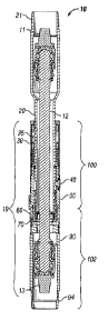
Figure 1 is an axial cross section of a surface-actuated downhole-adjustable
mud motor bent sub
according to a preferred embodiment, showing an adjustable bent section,
presently set with a
lb
CA 2929081 2017-09-08
CA 02929081 2016-04-28
WO 2015/099652
PCT/US2013/077436
zero-degree bend, for inclusion between an upper power section and a lower
bearing section of a
mud motor;
Figure 2 is an enlarged elevation of a spline shaft of the bent sub of Figure
1, showing features
used for the transmission of weight on bit, rotary drilling torque, and
selective adjustment of
bend angle;
Figure 3 is an enlarged exploded diagram in axial cross section of the spline
shaft of Figure 2 and
a lock housing assembly, showing a latch system that transfers weight on bit
and prevents
adjustment of bend angle until a maximum operational weight on bit set point
is exceeded;
Figure 4 is an enlarged exploded diagram in axial cross section of a knuckle
assembly of the bent
sub of Figure 1, showing a knuckle housing, a knuckle lock ring, and a knuckle
extension with
radially extending shoes for engaging the sides of the bore hole while
adjusting bend angle.
Figure 5 is an enlarged perspective view of a shoe of Figure 4, showing the
serrated outer surface
for engaging the sides of the bore hole while adjusting bend angle;
Figure 6 is a detailed axial cross section of a portion of the knuckle
extension of Figure 4 and the
shoe of Figure 5, showing springs for urging the shoe radially inward and
sectioned rings for
securing the shoe within a pocket formed through the wall of the knuckle
extension;
Figure 8 is an enlarged axial cross section of the knuckle housing of Figure
4, showing a radially
collapsible spline for transmission of drill string torque, a mouth into which
a setting ring is
received, a circumferential array of toggles for rotatively fixing the setting
ring;
Figure 9 is an enlarged exploded diagram in axial cross section, showing the
assembly of a
setting ring and lower housing with the assembled spline shaft of Figure 2,
lock housing
assembly of Figure 3, and the knuckle assembly of Figure 4, with the spline
shaft located in an
upper normal torque transfer position with respect to the lock housing and
knuckle assembly;
Figure 10A is a perspective view of the upper end of the setting ring of
Figure 9, showing the
internal spline for adjustment of bend angle and slots formed in the outer
circumference at an
upper face for maintaining a set bend angle;
2
CA 02929081 2016-04-28
WO 2015/099652
PCT/US2013/077436
Figure 10B is an enlarged axial cross section of the setting ring of Figure
10A, showing a lower
face that is tapered with respect to the upper face;
Figure 10C is a perspective view of the lower end of the setting ring of
Figure 10A, showing the
internal spline for adjustment of bend angle and slots formed in the outer
circumference of the
upper face for maintaining a set bend angle;
Figure 11 is a perspective view of the upper end of the lower housing of
Figure 9, showing a
fixed boss and a number of spring-loaded telescopic tension buttons for
abutment with the lower
face of the setting ring of Figure 10C;
Figure 12 is a detailed axial cross section of the setting ring of Figure 10B
received in the mouth
of the knuckle housing of Figure 9, which is in turn received in the knuckle
lock ring of Figure 9,
showing toggles having fingers received into slots in the upper face of the
setting ring for
preventing relative rotation between the setting ring and the knuckle housing,
thereby
maintaining a set bend angle;
Figure 13 is the detailed axial cross section of Figure 12, showing the
toggles in a flipped state
due to displacement by the spline shaft of Figure 2 thereby allowing relative
rotation between the
setting ring and the knuckle housing for adjusting bend angle;
Figure 14 is an axial cross section of thc surface-actuated downhole-
adjustable mud motor bent
sub of Figure 1, showing the tool in a maximum bend configuration;
Figure 15 is an enlarged axial cross section of the assembled spline shaft,
lock housing
assembly, and knuckle assembly of Figure 9, showing the spline shaft axially
displaced within
the lock housing assembly to a lower bend setting position for adjusting the
bend angle; and
Figure 16 is an elevation view in partial cross section of a drilling system
according to an
embodiment that employs the surface-actuated downhole-adjustable mud motor
bent sub of
Figures 1-15.
3
CA 02929081 2016-04-28
WO 2015/099652
PCT/US2013/077436
DETAILED DESCRIPTION
Structure of Tool
Figure 1 illustrates the bent sub tool 10 in a straight configuration
according to a preferred
embodiment, and Figure 14 illustrates the same bent sub tool 10 in a maximum
bent
configuration. An upper housing assembly 100 includes a lock housing assembly
30, a knuckle
extension 50, and a knuckle housing 70. A lower housing assembly 102 includes
a lower
housing 90 and a knuckle lock ring 60. The complete housing assembly 19
includes the upper
housing assembly 100 and the lower housing assembly 102.
Bent sub tool 10 includes upper and lower pin connectors 21, 94 and a constant
velocity shaft
assembly 12 with upper and lower pin connectors 11, 13. Bent sub tool 10
includes a spline sub
20, which terminates at its upper end with pin connection 21. Pin connection
21 connects with a
box connector at the bottom end of an upper housing, or stator, of a mud motor
power section
190 (Figure 16) that transmits power to the drill bit 192 (Figure 16). The mud
motor power
section is supported from a drill string 132 (Figure 16) that extends to the
surface. The lower pin
connector 94 connects to a bearing section 194 (Figure 16) of a conventional
mud motor. The
rotor from the mud motor power section (not expressly shown) connects within
the spline sub 20
to the constant velocity shaft assembly 12 at upper connector 11. The mud
motor power section
190 (Figure 16) is operable to rotate drill bit 192 (figure 16) via constant
velocity shaft assembly
12, In addition to accommodating power transmission over the bend angle,
constant velocity
shaft assembly 12 allows for the spiraling nutation of the power section of
the mud motor..
As is described in greater detail below, the lower end of spline sub 20 is
received within and has
limited axial and rotational movement with respect to a complete housing
assembly 19, which
includes, among other components, a lock housing 30, a knuckle extension 50, a
knuckle lock
ring 60, and a knuckle housing 70, and a lower housing 90.
Referring to Figures 2 and 3, spline sub 20 has an upper pin end 21 for
connecting to the power
section stator (not illustrated) and a lower spline end 22. Lower spline end
22 has six notable
features: Latch grooves 24, upper spline 25, bosses 26, lower spline 27,
tapered shoulder 28, and
stopper ring groove 29.
4
CA 02929081 2016-04-28
WO 2015/099652 PCT/U
S2013/077436
Latches 35 within lock housing 30 engage latch grooves 24 to substantially
prevent axial
movement of splined sub 20 with respect to lock housing 30 until a
predetermined maximum
weight on bit set point is exceeded, as is described in further detail with
respect to Figures 9 and
15 below.
Upper spline 25 is used when torque is applied to the drill string during
vertical drilling
operation. Upper spline 25 engages with the collapsible splines 71 provided in
the inside portion
of knuckle housing 70 (best seen in Figures 4 and 8) to allow complete housing
assembly 19 to
rotate when torque is applied. Collapsible splines 71 remain in a normal
radial inward position
for torque transfer, and only collapse into the slots 77 formed in knuckle
housing 70 (Figure 8) as
necessary to allow spline shaft 20 to be withdrawn upwards from a lower, bend
setting position
to the upper, normal torque transfer position, as described in greater detail
below.
Bosses 26 are formed on the external surface of spline sub 20 and engage a
circumferential array
of inwardly protruding arches 78 formed on the interior wall of knuckle
housing 70 to allow easy
disengagement of spline sub 20 after bend setting adjustment, as described in
greater detail
below.
Lower spline 27 engages with internal spline 84 provided in the inside
diameter of a tapered
setting ring 80 (Figures 10A-10C) only during adjustment of bend angle or
inclination. Using
lower spline 27, setting ring 80 can be rotated about the drill string axis
with respect to lock
housing 30, knuckle extension 50, knuckle lock ring 60, and knuckle housing
70, as described in
greater detail below.
Tapered shoulder 28 at the lower end 22 of spline sub 20 is used to engage
tapered surfaces 42 of
shoes 40 (Figures 4, 6, and 9, for example) and convert downward axial force
on spline sub 20 to
radial outward force of shoes 40 out during adjustment of bend angle or
inclination, as is
described in greater detail below.
Finally, stopper ring groove 29 receives stopper ring 38.
Referring to Figure 3, lock housing 30 is a cylindrical housing, open at both
ends, having threads
31 on its lower inner diameter for connection to the upper end of knuckle
extension 50 (Figure
4). Lock housing 30 houses retainer rings 33, 34, latches 35, belleville
springs 36, spacer ring
5
CA 02929081 2016-04-28
WO 2015/099652
PCT/US2013/077436
37, and stopper ring 38. An 0-ring groove 32 is formed on its upper inner
diameter for sealing
against spline sub 20.
Referring to Figure 4, knuckle extension 50 has three noteworthy features: A
first feature is the
provision of T-shaped cavities or pockets 51, into which shoes 40 are
received, In a preferred
embodiment, three spaced pockets 51 are provided (only two are visible in
Figure 4) at equally
spaced 120 degree intervals about the circumference of knuckle extension 50.
However, a
greater or lesser number of pockets 51 may be provided as appropriate. A
second feature is the
provision of an interior spherical surface 52 at the bottom end of knuckle
extension 50, whose
center point acts as the pivot point for bend setting. Spherical surface 52
mates with the exterior
spherical surface feature 62 at the top end of the knuckle lock ring 60. A
third feature is
provision for low side button carbide inserts 57 on the outside, which sustain
the side load forces
when the bent sub tool 10 is operating in a bent position. Knuckle extension
50 has internal
threads 54 in its lower end that engage with the external threads 74 of
knuckle housing 70.
Referring to Figures 4-6, shoe 40 is a component that has a gripping feature
on its outer face 41
and an inclined face 42 on an inner cylindrical stem 43. In certain
embodiments, the gripping
feature may be serrated or textured. A number of shoes 40 sit in pockets 51
provided on the
outer surface of the knuckle extension 50. Shoe lock ring 55 is a simple ring
split into two
halves 55', 55" that is used to hold shoes 40 within pockets 51 in knuckle
extension 50. Springs
53 are provided between shoes 40 and shoe lock rings 55 to urge the shoes 40
inside towards the
tool axis.
During bend setting operations, the tapered shoulder 28 at the lower end 22 of
spline sub 20
(Figures I and 3) pushes against tapered surfaces 42 to force shoes 40
radially outward to grip
the formation for constraining rotation of the knuckle extension 50 and to
provide the directional
reference.
Referring to Figures 1, 4 and 9, knuckle lock ring 60 has internal threads 61
which mate with
external threads 91 of lower housing 90. Knuckle lock ring 60 also features
two spherical
surfaces. External spherical surface 62 at the upper end of knuckle lock ring
60 mates with
internal spherical surface 52 of knuckle extension 50. Internal spherical
surfaces 63 mates with
the external spherical surface 73 on knuckle housing 70. Thus, lower housing
assembly 102 is
6
CA 02929081 2016-04-28
WO 2015/099652
PCT/US2013/077436
pivotally connected to the upper housing assembly 100 by being sandwiched
between the
internal spherical surface 52 and the external spherical surface 73 of the
upper housing assembly.
Knuckle lock ring 60 also has an inwardly projecting key 64 having a spherical
profile that fits
into a spherically shaped keyway slot 72 formed in knuckle housing 70. Key 64
and slot 72 are
provided to restrict relative rotational motion between knuckle lock ring 60
and knuckle housing
70 about the tool longitudinal axis. Projecting key 64 and keyway slot '72
permit movement only
within a single geometric plane between knuckle lock ring 60 and knuckle
housing 70. Although
one projecting key 64 and keyway slot 72 are illustrated for simplicity, two
such features may be
provided 180 degrees apart.
Referring now to Figures 4, 8, and 9, knuckle housing 70 assists in tilting
lower housing 90 with
respect to knuckle extension 50. It is the primary component that restricts
independent rotation
of lower housing 90 about the tool axis and allows only tilting. Knuckle
housing 70 defines a
mouth 88 into which a setting ring 80 is received and a shoulder 89 against
which the upper face
82 of setting ring 80 seats.
Knuckle housing 70 includes external threads 74 that are threaded to internal
threads 54 of
knuckle extension 50. One or two spherically-profiled slots 72 on the exterior
surface of knuckle
housing 70 are provided to engage knuckle lock ring keys 64 to prevent
relative rotation
therebetween, as previously described.
Knuckle housing 70 includes a circumferential array of small slots 79 formed
in its interior wall,
into which V-shaped two-fingered toggles 75 are received and pivotally mounted
using pins.
Torsion springs 76A are mounted about the toggle pivot pins and operate to
urge toggles 75
radially inward. Toggles 75 are used to selectively hold setting ring 80
rotationally stationary
with respect to knuckle housing 70 and thereby maintain a particular bend
angle for drilling a
curved section of a well, as described in greater detail below with respect to
Figures 12 and 13.
Knuckle housing 70 also includes a circumferential array of larger slots 77
formed in its interior
wall into which tapered radially-adjustable splines 71 are slideably received.
Adjustable internal
splines 71 are independently radially movable with respect to knuckle housing
70 and are urged
radially inward by springs 76B. Adjustable internal splines 71 function to
transmit torque from
7
CA 02929081 2016-04-28
WO 2015/099652
PCT/US2013/077436
upper splines 25 of spline sub 20 to the knuckle housing 70 during drilling
operations, but are
arranged to collapse as necessary upon raising spline shaft 20 from a lower
bend setting position
to an upper normal torque transfer position.
Finally, knuckle housing 70 has an circumferential array of inwardly
protruding arches 78
formed in its interior wall that engage with bosses 26 on lower spline end 22
of spline sub 20
(see Figure 3) to allow easy exit of spline sub 20 from setting ring 80 after
bend setting
adjustment, as described in greater detail below.
Referring to Figures 9-11, lower housing 90 has one or more fixed bosses 92
axially extending
from one lateral side of its upper end, which abuts the lower face 81 of
setting ring 80. On the
opposite lateral side of its upper end, lower housing 90 has one or more
spring-loaded tension
buttons 93, which assist in holding the bent sub for building or dropping the
inclination. Each
tension button 93 includes a hollow cap 95 that tits over a post 96, with a
spring 97 positioned
therebetween that urges cap 95 axially upwards.
Setting ring 80 has an upper face 82, which is received into mouth 88 and
seated against shoulder
89 of knuckle housing 70. Setting ring 80 has a lower face 81, or bearing
surface, upon which
axially-oriented fixed boss 92 and telescopically adjustable tension buttons
93 of lower housing
90 bear. Preferably, there is a three degree taper provided on the lower face
81 as compared to
the upper face 82, as indicated by arrows 83 in Figure 10B. In one embodiment,
the taper is
approximately three degrees. In another embodiment, the taper is no more than
eight degrees.
Accordingly, about its circumference, sctting ring 80 defines a point 86 of
minimum axial length
and, 180 degrees about its axial centerline, a point 87 of maximum axial
length.
The rotational position of setting ring 80 with respect to knuckle housing 70
determines the bend
of tool 10. The axial length of fixed boss 92 is set so that when setting ring
80 is oriented such
that the point 86 of minimum axial length is aligned with fixed boss 92, tool
10 has a zero degree
bend, as shown in Figure 1. When setting ring is rotated 180 degrees so that
the point 87 of
maximum axial length aligns with fixed boss 92, tool 10 has a maximum bend
wherein the taper
determines the maximum bend angle. For example, a setting ring 80
characterized by a three
degree taper has a maximum bend angle of three degrees.
8
CA 02929081 2016-04-28
WO 2015/099652
PCT/US2013/077436
Slots 85 on the outer circumference at the upper face 82 are for receiving
toggles 75 to hold
setting ring 80 in a particular bend position. Internal splines 84 are used to
rotate setting ring 80
using lower spline 27 of the spline sub 20. A needle bearing assembly (not
illustrated) can be
provided between the setting ring 80 and knuckle housing 70 to promote ease of
relative rotation.
Alternatively, the surfaces can also be made smooth and function as a plain
bearing.
Referring now to Figures 9 and 11, lower housing 90 has exterior threads 91 at
its upper end for
mating to internal threads 61 at the bottom end of knuckle lock ring 60. The
lower end of lower
housing 90 has external threads 94 for connection to a bearing section of a
conventional mud
motor. As mud motor bearing sections are known to routineers in the art, such
is not illustrated
or described further herein. Lower housing 90 accommodates constant velocity
shaft assembly
12 and its lower connector 13 (Figure ) with enough room to accommodate the
nutations
induced by the mud motor power section.
Operation of Tool During Drilling
Referring primarily to Figures 1, 8, and 9, during rotary drilling operations,
spline sub 20 is
axially positioned with respect to complete housing assembly 19 such that
upper spline 25 is
positioned adjacent to and meshes with collapsible splines 71 of knuckle
housing 70. During this
time, collapsible splines 71 remain in their normal radial inward positions as
urged by springs
76B. As spline sub 20 is rotated by the drill pipe via connector 21, splines
25, 71 transfer the
drill string torque to the knuckle housing 70. Projecting key 64 and keyway
slot 72 transfer the
rotational torque of knuckle housing 70 to knuckle lock ring 60, which in turn
transfers the
rotational torque to the remainder of the complete housing assembly 19,
including connector 94
of lower housing 90.
During this time, toggles 75 are oriented by springs 76A so that they are
pivoted radially inward
(see Figure 12). Accordingly, the outer fingers of toggles 75 are received
into slots 85 in setting
ring 80, thereby causing setting ring 80 to rotate with knuckle housing 70.
Because toggles 85
prevent any relative motion between the setting ring 80 and the lower housing
90, the bend angle
does not change.
9
CA 02929081 2016-04-28
WO 2015/099652
PCT/US2013/077436
Weight on bit is transferred from the drill string to spline sub 20 via pin
connector 21. Belleville
springs 36 urge lower retaining ring 34 upwards, compressing latches 35
between the tapered
surfaces of upper and lower retaining rings 33, 34 and forcing latches 35
radially inward into
intimate contact with latch grooves 24 of spline sub 20. The belleville
springs 36 are selected
and designed so that latches 35 remain engaged with latch grooves 24 so long
as maximum
operation weight on bit set points are not exceeded. Latch grooves 24 and
latches 35 preferably
have complementary tapered serrated profiles. Accordingly, downward axial
weight in bit is
transferred from spline shaft 20 through latch grooves 24 to latches 35, and
through lower
retaining ring 34, belleville springs 36, and spacer ring 37 to knuckle
extension 50. The lower
spherical surface 52 of knuckle extension 50 transfers the downward axial
force to the upper
spherical surface 62 of knuckle lock ring 60. Finally, knuckle lock ring 60
transfers weight on
bit via threads 61, 91, lower housing 90, and lower pin connector 94.
Operation of Tool During Bend Setting
Referring to Figures 1 and 15, when drilling has advanced to a "kick-off
point, it may be desired
to adjust the bend angle of tool 10. Drill string rotation and drilling fluid
circulation are stopped.
Weight on bit is applied, which causes the serrated beveled latch grooves 24
of spline sub 20 to
apply radially outward force against latches 35, which in turn, due to the
lower beveled surface
of the latches 35, applies an axial downward force on lower retaining ring 34
and belleville
springs 36. When weight on bit exceeds the maximum operational set point,
belleville springs
36 are sufficiently compressed so as to allow latches 35 to move radially
outward far enough to
disengage from latch grooves 24. At this time, spline sub 20 moves axially
downward within the
complete housing assembly 19 until stopper ring 38 seats against an internal
shoulder 39 formed
in knuckle extension 50.
As shown in Figure 12, in the default, radially inward position, the outer
fingers of toggles 75
extend axially downward into an engaged position so as to engage slots 85 in
setting ring 80,
thereby holding setting ring 80 rotationally stationary with respect to
knuckle housing 70. As
shown in Figure 13, during bend setting adjustment, as spline sub 20 moves
axially downward,
its lower end 22 first contacts the inner fingers of toggles 75, flipping the
toggles to the radially
outward position. In the radially outward position, the outer fingers of
toggles 75 are pivoted to
CA 02929081 2016-04-28
WO 2015/099652
PCT/US2013/077436
a disengaged position so as to be clear of slots 85 in setting ring 80,
thereby allowing rotation of
setting ring 80 with respect to knuckle housing 70. As spline sub 20 continues
its axial
downward movement, lower external spline 27 of spline shaft 20 engages
internal spline 84 of
setting ring 80.
As illustrated by Figures I, 9 and 15, shoes 40 move radially outward due to
the downward
sliding of spline sub 20, in which tapered shoulder 28 contacts tapered
surfaces 42 of shoes 40 as
described above. Shoes 40 engage the borehole wall to hold tool 10 stationary
with respect to
the formation to establish a reference point and to allow the drill string to
rotate spline sub 20
and setting ring 80 with respect to the complete housing assembly 19 during
bend setting
operations.
Lower spline 27 of spline sub 20 engages and meshes with internal spline 84 of
setting ring 80
during bend setting. From the zero degree bend configuration of Figure 1, when
spline sub 20 is
rotated by 180 degrees, the lower tapered face 81 of setting ring 80 causes
the lower housing to
tilt to its extreme tilted position, as shown in Figure 14. The tilting
relationship is linearly
related to the slope of lower face 81 of setting ring 80. That is, if lower
face 81 has a three
degree inclination, then the lower housing 90 will also tilt by three degrees.
The minimum
amount that tilting can be adjusted, i.e., the maximum tilting resolution or
the least achievable tilt
adjustment, is determined by the number and circumferential spacing of toggles
75.
Once the desired bend is set, weight on bit is reduced and spline sub 20 is
raised with respect to
complete housing assembly 19. Once the lower end 22 of spline sub 20 clears
toggles 75, toggle
springs 76A force toggles 75 to the radially inward position to reengage slots
85, thereby holding
setting ring 80 in its new position with respect to knuckle housing 70.
A particular scenario may occur while pulling spline sub 20 from setting ring
80 after bend
setting. It may happen that the outer fingers of toggles 75 are not aligned
with slots 85 in setting
ring 80. In this case setting ring 80 is not locked to knuckle housing 70.
Accordingly, to avoid
this situation, bosses 26 are provided on the outer surface of spline sub 20
(Figure 2) and arcuate
protrusions, i.e., inwardly protruding arches, 78 are provided in the internal
surface of knuckle
housing 70 (Figure 8). As spline sub 20 is raised, bosses 26 engage arches 78
and force spline
11
CA 02929081 2016-04-28
WO 2015/099652
PCT/US2013/077436
sub 20 to rotate to fully disengage from setting ring 80. This action
rotatively aligns toggles 75
with slots 85 in setting ring 80.
Figure 16 illustrates a drilling system 120 according to an embodiment that
employs bent sub
tool 10. Drilling system 120 may include land drilling rig 122. However,
teachings of the
present disclosure may be satisfactorily used in association with offshore
platforms, semi-
submersible, drill ships and any other drilling system satisfactory for
forming a wellbore
extending through one or more downhole formations.
Drilling rig 122 may be located proximate well head 124. Drilling rig 122 also
includes rotary
table 138, rotary drive motor 140 and other equipment associated with rotation
of drill string 132
within well bore 160. Annulus 166 may be formed between the exterior of drill
string 132 and
the inside diameter of wellbore 160.
Drilling rig 122 may also include top drive motor or top drive unit 142. Blow
out preventers (not
expressly shown) and other equipment associated with drilling a wellbore may
also be provided
at well head 124. One or more pumps 148 may be used to pump drilling fluid 146
from fluid
reservoir or pit 130 to one end of drill string 132 extending from well head
124. Conduit 134
may be used to supply drilling mud from pump 148 to the one end of drilling
string 132
extending from well head 124. Conduit 136 may be used to return drilling
fluid, formation
cuttings and/or downhole debris from the bottom or end 162 of wellbore 160 to
fluid reservoir or
pit 130. Various types of pipes, tube and/or conduits may be used to form
conduits 134 and 136.
Drill string 132 may extend from well head 124 and may be coupled with a
supply of drilling
fluid such as pit or reservoir 130. The opposite end of drill string 132 may
include bottom hole
assembly 189 and rotary drill bit 192 disposed adjacent to end 162 of wellbore
160. Rotary drill
bit 192 may include one or more fluid flow passageways with respective nozzles
(not expressly
illustrated) disposed therein. Various types of drilling fluids 146 may be
pumped from reservoir
130 through pump 148 and conduit 134 to the end of drill string 132 extending
from well head
124. The drilling fluid 146 may flow through a longitudinal bore (not
expressly shown) of drill
string 132 and exit from the nozzles 16 formed in rotary drill bit 192.
12
CA 02929081 2016-04-28
WO 2015/099652
PCT/US2013/077436
At end 162 of wellbore 160, drilling fluid 146 may mix with formation cuttings
and other
downhole debris proximate drill bit 192. The drilling fluid will then flow
upwardly through
annulus 166 to return formation cuttings and other downhole debris to well
head 124. Conduit
136 may return the drilling fluid to reservoir 130, Various types of screens,
filters and/or
centrifuges (not shown) may be provided to remove formation cuttings and other
downhole
debris prior to returning drilling fluid to pit 130.
Bottom hole assembly 189 includes mud motor power section 190, bent sub
assembly 10, and
mud motor bearing section 194. Bottom hole assembly 189 may also include
various other tools
(not illustrated) that provide logging or measurement data and other
information from the bottom
of wellbore 160.
In summary, a downhole tool, drilling system, and a method for adjusting the
bend angle of a
downhole tool have been described. Embodiments of the downhole tool may
generally have an
upper housing assembly, a setting ring having a tapered bearing surface
disposed within the
upper housing assembly, a spline sub arranged for connection to a drill
string, the spline sub
being axially movable with respect to the upper housing assembly and the
setting ring between a
normal position in which torque is transferred between the spline sub and the
upper housing
assembly and a bend setting position in which torque is transferred between
the spline sub and
the setting ring so as to allow rotation of the setting ring with respect to
the upper housing
assembly, and a lower housing assembly pivotally coupled to the upper housing
assembly and
bearing against the bearing surface of the setting ring, whereby the
rotational position of the
setting ring with respect to the upper housing assembly determines the pivot
angle of the lower
housing assembly with respect to the upper housing assembly. Embodiments of
the drilling
system may generally have a drill string, a spline sub coupled to the drill
string and partially
received within and axially movable with respect to an upper housing assembly,
a setting ring
having a tapered bearing surface disposed within the upper housing assembly,
the spline sub
being axially movable with respect to the setting ring between a normal
position in which torque
is transferred between the spline sub and the upper housing assembly and a
bend setting position
in which torque is transferred between the spline sub and the setting ring so
as to allow rotation
of the setting ring with respect to the upper housing assembly, and a lower
housing assembly
pivotally coupled to the upper housing assembly and bearing against the
bearing surface of the
13
CA 02929081 2016-04-28
WO 2015/099652
PCT/US2013/077436
setting ring, whereby the rotational position of the setting ring with respect
to the upper housing
assembly determines the pivot angle of the lower housing assembly with respect
to the upper
housing assembly. Embodiments of the method for adjusting the bend angle of a
downhole tool
may generally include providing an upper housing assembly, providing a setting
ring having a
tapered bearing surface within the upper housing assembly, providing a spline
sub arranged for
connection to a drill string, the spline sub being axially movable with
respect to the upper
housing assembly and the setting ring, providing a lower housing assembly
pivotally coupled to
the upper housing assembly and bearing against the bearing surface of the
setting ring, lowering
the spline sub from a normal position in which torque is transferred between
the spline sub and
the upper housing assembly to a bend setting position in which torque is
transferred between the
spline sub and the setting ring so as to allow rotation of the setting ring
with respect to the upper
housing assembly, and then rotating the setting ring by rotating the spline
sub, whereby the
rotational position of the setting ring with respect to the upper housing
assembly determines the
pivot angle of the lower housing assembly with respect to the upper housing
assembly.
Any of the foregoing embodiments may include any one of the following elements
or
characteristics, alone or in combination with each other: A toggle coupled to
the upper housing
assembly so as to have an engaged position in which the toggle fixes the
setting ring to the upper
housing assembly and a disengaged position in which the setting ring can be
rotated with respect
to the upper housing assembly; the toggle is positioned so that spline sub in
the bend setting
position forces the toggle into the disengaged position; the spline sub
includes an upper spline
and a lower spline; the setting ring includes an internal spline; the upper
housing assembly
includes an internal spline; when the spline sub is in the normal position,
the upper spline
engages the internal spline of the upper housing assembly and the lower spline
of the spline sub
does not engage the internal spline of the setting ring; when the spline sub
is in the bend setting
position, the lower spline engages the internal spline of the setting ring and
the upper spline does
not engage the internal spline of the upper housing assembly; a pocket formed
in a wall of the
upper housing assembly; a shoe disposed the cavity so as to be movable in a
radial direction, the
shoe having an inclined face on an interior end; a tapered shoulder formed on
the spline sub; the
tapered shoulder is positioned so as to engage the inclined face and force the
shoe radially
outward when the spline sub is in the bend setting position; a spring coupled
between the spline
sub and the upper housing assembly urging the spline sub toward the normal
position; a latch
14
CA 02929081 2016-04-28
WO 2015/099652
PCT/US2013/077436
groove formed about the spline sub; a latch disposed within the upper housing
assembly and
urged radially inward by the spring so as to engage the latch groove; the
upper housing assembly
includes an internal spherical surface and an external spherical surface; the
lower housing
assembly has an external spherical surface that mates with the internal
spherical surface of the
upper housing assembly; the lower housing assembly has an internal spherical
surface that mates
with the external spherical surface of the upper housing assembly; the lower
housing assembly is
pivotally connected to the upper housing assembly by being sandwiched between
the internal
spherical surface of the upper housing assembly and the external spherical
surface of the upper
housing assembly; the upper housing assembly includes a knuckle extension that
defines the
internal spherical surface of the upper housing assembly; the upper housing
assembly includes a
knuckle housing that is threaded to the knuckle extension; the knuckle housing
defines the
external spherical surface of the upper housing assembly; the lower housing
assembly is
pivotally captured between the knuckle extension and the knuckle housing; the
knuckle housing
defines a mouth; the setting ring is received into the mouth of the knuckle
housing; a plurality of
toggles coupled to the knuckle housing and pivotal between an engaged position
that fixes the
setting ring within the mouth and a disengaged position in which the setting
ring can be rotated
within the mouth; the setting ring includes a plurality of slots; the
plurality of toggles is
selectively partially received in the plurality of slots; a boss formed on an
external surface of the
spline sub; an arcuate protrusion formed on an internal surface of the knuckle
housing; an
interaction between the boss and the arcuate protrusion causes the plurality
of slots to rotatively
align with the plurality of toggles; a boss connected to the lower housing
assembly and bearing
against the bearing surface of the setting ring; a telescopically adjustable
button disposed
between the lower housing assembly and the bearing surface of the setting
ring; a spring
disposed between the button and the lower housing assembly urging the button
against the
bearing surface; a constant velocity shaft assembly disposed within the spline
sub, the upper
housing assembly, and the lower housing assembly; a mud motor power section
coupled between
the drill string and the upper housing assembly; a mud motor bearing section
coupled to the
lower housing assembly; a constant velocity shaft assembly at least partially
disposed within the
spline sub and coupled between the mud motor power section and the mud motor
bearing
section; providing a pocket formed in a wall of the upper housing assembly;
disposing a shoe in
the cavity so as to be movable in a radial direction, the shoe having an
inclined face on an
interior end; providing a tapered shoulder formed on the spline sub, the
tapered shoulder being
positioned so as to engage the interior face and force the shoe radially
outward when the spline
sub is in the bend setting position; lowering the spline sub from the normal
position to the bend
setting position to thereby move the shoe radially outward; providing a toggle
coupled to the
upper housing assembly so as to have an engaged position in which the toggle
fixes the sctting
ring to the upper housing assembly and a disengaged position in which the
setting ring can be
rotated with respect to the upper housing assembly; lowering the spline sub
from the normal
position to the bend setting position to thereby move the toggle to the
disengaged position; and
providing a spring coupled between the spline sub and the upper housing
assembly urging the
I 0 spline sub toward the normal position.
The Abstract of the disclosure is solely for providing the Office and the
public at large with a
way by which to determine quickly from a cursory reading the nature and gist
of technical
disclosure, and it represents solely one or more embodiments.
While various embodiments have been illustrated in detail, the disclosure is
not limited to the
embodiments shown. Moditications and adaptations of the above embodiments may
occur to
those skilled in the art. Such modifications and adaptations are in the scope
of the appended
claims.
16
CA 2929081 2017-09-08