Note: Descriptions are shown in the official language in which they were submitted.
CA 02929135 2016-05-06
INTERNAL TANK HEATING COIL
COPYRIGHT STATEMENT
[001] All of the material in this patent document is subject to copyright
protection under the
copyright laws of the United States and other countries. The copyright owner
has no
objection to the facsimile reproduction by anyone of the patent document or
the patent
disclosure, as it appears in official governmental records but, otherwise, all
other copyright
rights whatsoever are reserved.
BACKGROUND OF THE INVENTION
[002] The present invention generally relates to tank heating.
[003] Natural gas wells generally have storage tanks that are used to hold
oil, water, and
other production fluids after they are extracted from the ground. In cold
climates, or where
the fluids are waxy, the tanks require supplemental heat to ensure the
products do not freeze
and are kept in a liquid state. Conventionally, the primary method for heating
these tanks is
direct-fired gas heaters which blow burning gas into a tank within a contained
pipe. The gas
is burned, creating heat which then heats the product inside the tank. The
waste heat from
this burner is sent into a stack which carries the wasted energy and
combustion byproducts to
the top of the tank and into the atmosphere.
[004] A need exists for improvement in tank heating. This need and other needs
are
addressed by one or more aspects of the present invention.
SUMMARY OF THE INVENTION
[005] The present invention includes many aspects and features. Moreover,
while many
aspects and features relate to, and are described in, a particular context,
the present invention
is not limited to use only in this context, as will become apparent from the
following
summaries and detailed descriptions of aspects, features, and one or more
embodiments of
the present invention.
[006] Accordingly, one aspect of the present invention relates to a system for
heating a
vessel comprising a U-shaped pipe disposed proximate a bottom of a vessel, a
majority of the
extent of the U-shaped pipe being disposed within an interior of the vessel; a
catalyst unit
embedded within the U-shaped pipe, the catalyst unit comprising a catalyst
wrapped, natural
gas filled, perforated pipe that is configured to enable a catalytic reaction
on its exterior; a
1
CA 02929135 2016-05-06
vent pipe attached to the U-bend pipe which allows air to circulate; and
mechanical controls
disposed proximate the U-shaped pipe configured to vary temperature output.
[007] Another aspect relates to a system for heating a vessel comprising a
tank containing a
fluid to be heated; a U-shaped pipe disposed proximate a bottom of the tank, a
majority of the
extent of the U-shaped pipe being disposed within an interior of the tank; a
catalyst unit
embedded within the U-shaped pipe, the catalyst unit comprising a catalyst
wrapped, natural
gas filled, perforated pipe that is configured to enable a catalytic reaction
on its exterior; a
vent pipe attached to the U-bend pipe which allows air to circulate; and
mechanical controls
disposed proximate the U-shaped pipe configured to vary temperature output.
[008] Another aspect relates to a method for heating a vessel comprising
starting a catalytic
reaction using a catalyst unit embedded within a U-shaped pipe, the U-shaped
pipe being
disposed proximate a bottom of a vessel, a majority of the extent of the U-
shaped pipe being
disposed within an interior of the vessel, the catalyst unit comprising a
catalyst wrapped,
natural gas filled, perforated pipe that is configured to enable a catalytic
reaction on its
exterior; varying a temperature output based on the catalytic reaction using
one or more
mechanical controls disposed proximate the U-shaped pipe.
[009]
[010] Another aspect relates to a system for heating a vessel comprising a
tank containing a
fluid to be heated; an outer shell comprising a tubular upper leg, a tubular
lower leg disposed
generally parallel to the tubular upper leg, wherein the tubular lower leg is
in fluid connection
with the tubular upper leg proximate a first end of the tubular lower leg,
wherein the tubular
lower leg comprises an access opening at a second end of the tubular lower leg
providing
access to an interior thereto; a catalyst insert disposed within the interior
of the tubular lower
leg, the catalyst insert comprising a central gas delivery tube comprising a
plurality of
openings disposed along its length for the outflow of gas from the gas
delivery tube, a
generally cylindrical perforated core surrounding the central gas delivery
tube, the perforated
core comprising a plurality of openings for facilitating flow of gas through
the perforated
core, refractory insulation wrapped around the outside of the perforated core,
a heating
element comprising a wire including a non-insulated segment of wire coiled
around the
outside of the refractory insulation generally down the entire length of the
catalyst insert, and
an insulated segment of wire running generally back up along the entire length
of the catalyst
insert, a catalyst element wrapped around the refractory insulation such that
the coiled wire is
disposed between the refractory insulation and the catalyst element, the
catalyst element
being configured to facilitate a catalytic reaction, front and end caps
configured to secure
2
CA 02929135 2016-05-06
components of the catalyst insert, the front cap comprising an opening for the
central gas
delivery tube, and an opening for one or more electrical connectors for the
heating element; a
vent apparatus connected to the tubular upper leg for venting gas byproducts
of the catalytic
reaction facilitated by the catalyst element; a temperature sensor configured
to monitor a
temperature proximate the catalyst element; a cover configured to generally
cover the access
opening of the tubular lower leg, the cover comprising a gas line opening
having a gas line
passing therethrough that is connected to the central gas delivery tube of the
catalyst insert, a
sensor opening having a connecting wire for the temperature sensor passing
therethrough,
one or more electrical openings having one or more electrical connectors for
the heating
element of the catalyst insert passing therethrough, one or more airflow
openings configured
to provide air to sustain a catalytic reaction; an automatic shutoff valve
configured to cease
the flow of gas through the gas line based on the temperature sensor if a
temperature drops
below a first predetermined threshold; an initiation button configured to
initiate a pre-heating
process comprising providing power to the heating element, automatically,
based on a
determination by the temperature sensor that a temperature proximate the
catalyst element
exceeds a second predetermined threshold, terminating the provision of power
to the heating
element, and opening the automatic shutoff valve allowing for the flow of gas
through the gas
line.
[011] In a feature of this aspect, the gas line provides natural gas.
[012] In a feature of this aspect, the temperature sensor comprises a
thermocouple.
[013] In a feature of this aspect, the catalyst element is configured to
facilitate a catalytic
reaction utilizing air and natural gas which generates byproducts of water,
carbon dioxide,
and heat.
[014] In a feature of this aspect, the catalyst element comprises an alumina-
silica pad
washed with elemental platinum to act as a hydrocarbon catalyst.
[015] In a feature of this aspect, the refractory insulation comprises an
alumina-silica pad.
[016] In a feature of this aspect, the first and second predetermined
thresholds are the same.
[017] In a feature of this aspect, the temperature sensor is a mechanical
sensor.
[018] In a feature of this aspect, the temperature sensor is a digital sensor.
[019] In a feature of this aspect, the first and second predetermined
thresholds are different.
[020] In a feature of this aspect, the first predetermined threshold is around
three hundred
degrees Fahrenheit.
[021] Another aspect relates to a method for heating a vessel, the method
involving a tank
containing a fluid to be heated; an outer shell comprising a tubular upper
leg, a tubular lower
3
CA 02929135 2016-05-06
leg disposed generally parallel to the tubular upper leg, wherein the tubular
lower leg is in
fluid connection with the tubular upper leg proximate a first end of the
tubular lower leg,
wherein the tubular lower leg comprises an access opening at a second end of
the tubular
lower leg providing access to an interior thereto; a catalyst insert disposed
within the interior
of the tubular lower leg, the catalyst insert comprising a central gas
delivery tube comprising
a plurality of openings disposed along its length for the outflow of gas from
the gas delivery
tube, a generally cylindrical perforated core surrounding the central gas
delivery tube, the
perforated core comprising a plurality of openings for facilitating flow of
gas through the
perforated core, refractory insulation wrapped around the outside of the
perforated core, a
heating element comprising a wire including a non-insulated segment of wire
coiled around
the outside of the refractory insulation generally down the entire length of
the catalyst insert,
and an insulated segment of wire running generally back up along the entire
length of the
catalyst insert, a catalyst element wrapped around the refractory insulation
such that the
coiled wire is disposed between the refractory insulation and the catalyst
element, the catalyst
element being configured to facilitate a catalytic reaction, front and end
caps configured to
secure components of the catalyst insert, the front cap comprising an opening
for the central
gas delivery tube, and an opening for one or more electrical connectors for
the heating
element; a vent apparatus connected to the tubular upper leg for venting gas
byproducts of the
catalytic reaction facilitated by the catalyst element; a temperature sensor
configured to
monitor a temperature proximate the catalyst element; a cover configured to
generally cover
the access opening of the tubular lower leg, the cover comprising a gas line
opening having a
gas line passing therethrough that is connected to the central gas delivery
tube of the catalyst
insert, a sensor opening having a connecting wire for the temperature sensor
passing
therethrough, one or more electrical openings having one or more electrical
connectors for
the heating element of the catalyst insert passing therethrough, one or more
airflow openings
configured to provide air to sustain a catalytic reaction; an automatic
shutoff valve configured
to cease the flow of gas through the gas line based on the temperature sensor
if a temperature
drops below a first predetermined threshold; and an initiation button
configured to initiate a
pre-heating process; wherein the method comprises, in response to pressing of
the initiation
button by a user, providing power to the heating element, automatically, based
on a
determination by the temperature sensor that a temperature proximate the
catalyst element
exceeds a second predetermined threshold, terminating the provision of power
to the heating
element, and opening the automatic shutoff valve allowing for the flow of gas
through the gas
line.
4
CA 02929135 2016-05-06
[022] Another aspect relates to a method for heating a vessel, the method
involving a tank
containing a fluid to be heated; an outer shell comprising a tubular upper
leg, a tubular lower
leg disposed generally parallel to the tubular upper leg, wherein the tubular
lower leg is in
fluid connection with the tubular upper leg proximate a first end of the
tubular lower leg,
wherein the tubular lower leg comprises an access opening at a second end of
the tubular
lower leg providing access to an interior thereto; a catalyst insert disposed
within the interior
of the tubular lower leg, the catalyst insert comprising a central gas
delivery tube comprising
a plurality of openings disposed along its length for the outflow of gas from
the gas delivery
tube, a generally cylindrical perforated core surrounding the central gas
delivery tube, the
perforated core comprising a plurality of openings for facilitating flow of
gas through the
perforated core, refractory insulation wrapped around the outside of the
perforated core, a
heating element comprising a wire including a non-insulated segment of wire
coiled around
the outside of the refractory insulation generally down the entire length of
the catalyst insert,
and an insulated segment of wire running generally back up along the entire
length of the
catalyst insert, a catalyst element wrapped around the refractory insulation
such that the
coiled wire is disposed between the refractory insulation and the catalyst
element, the catalyst
element being configured to facilitate a catalytic reaction, front and end
caps configured to
secure components of the catalyst insert, the front cap comprising an opening
for the central
gas delivery tube, and an opening for one or more electrical connectors for
the heating
element; a vent apparatus connected to the tubular upper leg for venting gas
byproducts of the
catalytic reaction facilitated by the catalyst element; a temperature sensor
configured to
monitor a temperature proximate the catalyst element; a cover configured to
generally cover
the access opening of the tubular lower leg, the cover comprising a gas line
opening having a
gas line passing therethrough that is connected to the central gas delivery
tube of the catalyst
insert, a sensor opening having a connecting wire for the temperature sensor
passing
therethrough, one or more electrical openings having one or more electrical
connectors for
the heating element of the catalyst insert passing therethrough, one or more
airflow openings
configured to provide air to sustain a catalytic reaction; an automatic
shutoff valve; wherein
the method comprises, when gas is flowing through the gas line to the gas
delivery tube of the
catalyst insert, in response to a determination by the temperature sensor that
a temperature
proximate the catalyst element has dropped below a first predetermined
threshold,
automatically closing the automatic shutoff valve to stop flow of the gas to
the gas delivery
tube of the catalyst element.
CA 02929135 2016-05-06
[023] In addition to the aforementioned aspects and features of the present
invention, it
should be noted that the present invention further encompasses the various
possible
combinations and subcombinations of such aspects and features. Thus, for
example, any
aspect may be combined with an aforementioned feature in accordance with the
present
invention without requiring any other aspect or feature.
BRIEF DESCRIPTION OF THE DRAWINGS
[024] One or more preferred embodiments of the present invention now will be
described in
detail with reference to the accompanying drawings, wherein the same elements
are referred
to with the same reference numerals, and wherein,
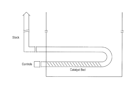
[025] FIG. 1 illustrates a system in accordance with one or more preferred
implementations;
[026] FIG. 2 is a schematic illustration of exemplary components of a system
in accordance
with one or more preferred implementations;
[027] FIGS. 3-4 illustrates insertion of a catalyst insert into an outer
shell;
[028] FIG. 5 is a partial, exploded view of one end of a catalyst insert;
[029] FIG. 6 is a partial, schematic illustration of a catalyst insert;
[030] FIG. 7 is a close up, partial view of a catalyst insert received within
a lower leg of an
outer shell;
[031] FIG. 8 depicts a fanciful, simplified exemplary cover which illustrates
features that
may be part of a cover in accordance with one or more preferred
implementations;
[032] FIG. 9 illustrates an exemplary, alternative design for an outer shell
in accordance with
one or more preferred implementations;
[033] FIG. 10 illustrates pieces which can be welded together to form the
outer shell of FIG. 9;
[034] FIGS. 11 and 12 provide additional different schematic views of the
outer shell of FIG.
9;
[035] FIG. 13 illustrates an exemplary, alternative design for a catalyst
insert; and
[036] FIG. 14 is an end-on view of the catalyst insert of FIG. 13.
DETAILED DESCRIPTION
[037] As a preliminary matter, it will readily be understood by one having
ordinary skill in
the relevant art ("Ordinary Artisan") that the present invention has broad
utility and
application. As should be understood, any embodiment may incorporate only one
or a
plurality of the above-disclosed aspects of the invention and may further
incorporate only one
or a plurality of the above-disclosed features. Furthermore, any embodiment
discussed and
6
CA 02929135 2016-05-06
identified as being -preferred" is considered to be part of a best mode
contemplated for
carrying out the present invention. Other embodiments also may be discussed
for additional
illustrative purposes in providing a full and enabling disclosure of the
present invention. As
should be understood, any embodiment may incorporate only one or a plurality
of the above-
disclosed aspects of the invention and may further incorporate only one or a
plurality of the
above-disclosed features. Moreover, many embodiments, such as adaptations,
variations,
modifications, and equivalent arrangements, will be implicitly disclosed by
the embodiments
described herein and fall within the scope of the present invention.
[038] Accordingly, while the present invention is described herein in detail
in relation to one
or more embodiments, it is to be understood that this disclosure is
illustrative and exemplary
of the present invention, and is made merely for the purposes of providing a
full and enabling
disclosure of the present invention. The detailed disclosure herein of one or
more
embodiments is not intended, nor is to be construed, to limit the scope of
patent protection
afforded the present invention in any claim of a patent issuing here from,
which scope is to be
defined by the claims and the equivalents thereof. It is not intended that the
scope of patent
protection afforded the present invention be defined by reading into any claim
a limitation
found herein that does not explicitly appear in the claim itself.
[039] Thus, for example, any sequence(s) and/or temporal order of steps of
various
processes or methods that are described herein are illustrative and not
restrictive.
Accordingly, it should be understood that, although steps of various processes
or methods
may be shown and described as being in a sequence or temporal order, the steps
of any such
processes or methods are not limited to being carried out in any particular
sequence or order,
absent an indication otherwise. Indeed, the steps in such processes or methods
generally may
be carried out in various different sequences and orders while still falling
within the scope of
the present invention. Accordingly, it is intended that the scope of patent
protection afforded
the present invention is to be defined by the issued claim(s) rather than the
description set
forth herein.
[040] Additionally, it is important to note that each term used herein refers
to that which the
Ordinary Artisan would understand such term to mean based on the contextual
use of such
term herein. To the extent that the meaning of a term used herein¨as
understood by the
Ordinary Artisan based on the contextual use of such term¨differs in any way
from any
particular dictionary definition of such term, it is intended that the meaning
of the term as
understood by the Ordinary Artisan should prevail.
7
CA 02929135 2016-05-06
[041] Regarding applicability of 35 U.S.C. 112, paragraph 6 or subsection (f),
no claim
element is intended to be read in accordance with this statutory provision
unless the explicit
phrase "means for" or "step for" is actually used in such claim element,
whereupon this
statutory provision is intended to apply in the interpretation of such claim
element.
[042] Furthermore, it is important to note that, as used herein, "a" and "an"
each generally
denotes "at least one," but does not exclude a plurality unless the contextual
use dictates
otherwise. Thus, reference to "a picnic basket having an apple" describes "a
picnic basket
having at least one apple" as well as "a picnic basket having apples." In
contrast, reference to
"a picnic basket having a single apple" describes "a picnic basket having only
one apple."
[043] When used herein to join a list of items, "or" denotes "at least one of
the items," but
does not exclude a plurality of items of the list. Thus, reference to "a
picnic basket having
cheese or crackers" describes "a picnic basket having cheese without
crackers", "a picnic
basket having crackers without cheese", and "a picnic basket having both
cheese and
crackers." Filially, when used herein to join a list of items, "and" denotes
"all of the items of
the list." Thus, reference to "a picnic basket having cheese and crackers"
describes "a picnic
basket having cheese, wherein the picnic basket further has crackers," as well
as describes "a
picnic basket having crackers, wherein the picnic basket further has cheese."
[044] Referring now to the drawings, one or more preferred embodiments of the
present
invention are next described. The
following description of one or more preferred
embodiments is merely exemplary in nature and is in no way intended to limit
the invention,
its implementations, or uses.
[045] In accordance with one or more preferred implementations, an internal
tank heating
coil uses a catalytic reaction as a heat source, e.g. a catalytic reaction
which produces
byproducts of heat, carbon dioxide, and water. Preferably, the catalytic
reaction is very
efficient (e.g. more gas is consumed in full than would occur in a simple
direct-fired heater)
and the byproduct results in far less smog causing emissions into the
atmosphere.
[046] In accordance with onc or more preferred implementations, an internal
tank heating
coil includes a ten foot long, catalyst wrapped, natural gas filled,
perforated pipe that is
configured to enable a catalytic reaction on its exterior. This unit is
embedded in a larger
pipe that is constructed in a U-bend shape and runs along the bottom of a
vessel, as illustrated
in FIG. 1. Preferably, a vent pipe is attached to the U-bend pipe allowing air
to circulate
through the system sustaining the catalytic reaction.
[047] Preferably, once the catalytic reaction begins (e.g. by heating the
catalyst to above 300
degrees Fahrenheit), the reaction is self-sustaining as long as air and
natural gas are supplied.
8
CA 02929135 2016-05-06
Preferably, the reaction can last for years before replacement or maintenance.
In one or more
preferred implementations, simple mechanical controls are set up to vary
temperature output.
[048] FIG. 2 is a schematic illustration of exemplary components of a system
in accordance
with one or more preferred implementations. These components include a
generally u-
shaped outer shell 10, and a catalyst insert 20. The u-shaped outer shell 10
comprises an
upper tubular leg 12 and a lower tubular leg 14 connected together at one end
by a curved
elbow 11.
[049] The upper and lower tubular legs 12,14 pass through, and are welded to,
a manway
cover 15. The manway cover 15 is preferably an American Petroleum Institute
(API)
standard manway cover. The u-shaped outer shell 10 can be installed in the
side of a tank by
passing the elbow 11 and the majority of the legs 12,14 through an
appropriately sized
opening in the tank and bolting the manway cover 15 to the exterior of the
tank, thereby
sealing the opening of the tank.
[050] In accordance with one or more preferred implementations, each of the
legs 12,14
includes a respective slip on flange 16,18 which provides access to a
respective opening
17,19 into the respective leg 12,14. Although one or more implementations are
described
herein as using a particular type of mechanical connector or connection, it
will be appreciated
that, in general, various different types of connections and connectors may be
utilized in
various implementations.
[051] The u-shaped outer shell 10 and the catalyst insert 20 are generally
sized and
dimensioned to allow the catalyst insert 20 to be inserted into and received
within the lower
leg 14 of the outer shell 10, as illustrated in FIGS. 3-4. In accordance with
one or more
preferred implementations, each leg 12,14 of the outer shell 10 generally is
comprised of four
inch schedule A40 pipe, and the catalyst insert generally has a diameter of
between two
inches and three and three fourth inches. In accordance with one or more
preferred
implementations, a catalyst insert has a diameter generally corresponding to
two inch
schedule A40 pipe.
[052] FIG. 5 is a partial, exploded view of one end of the catalyst insert 20,
and FIG. 6 is a
partial, schematic illustration of the catalyst insert 20.
[053] The catalyst insert 20 includes a gas delivery tube 26 running down its
center. The
gas delivery tube 26 includes a plurality of holes 27 configured to allow
outflow of natural
gas running through the gas delivery tube 26.
[054] The catalyst insert 20 further comprises a perforated core 25 which
includes a plurality
of perforation openings facilitating the flow of natural gas. In accordance
with one or more
9
CA 02929135 2016-05-06
preferred implementations, the perforated core 25 comprises metal configured
to withstand
temperatures of up to 900 degrees Fahrenheit.
[055] The catalyst insert 20 further includes refractory insulation 24 wrapped
around the
outside of the perforated core 25. The refractory insulation preferably
comprises a three
fourths inch thick alumina-silica refractory pad.
[056] The catalyst insert 20 further includes a catalyst element 22 wrapped
around the
outside of the refractory insulation 24. The catalyst element 22 comprises a
one fourth inch
thick alumina-silica pad washed with elemental platinum to act as a
hydrocarbon catalyst.
[057] The catalyst insert 20 further includes a heating element disposed
between the
refractory insulation 24 and the catalyst clement 22. The heating element
comprises exposed
nickel chromium wire coiled around the outside of the refractory insulation 24
down the
length of the catalyst insert 20. Although this coiled wire segment 31 is
uninsulated, a second
length of the wire (or a second, connected wire) that returns back up the
length of the catalyst
insert 20 is insulated and represents an insulated return wire segment 33.
Each end of the
chromium wire is configured for connection to a power source to form a
complete circuit and
cause the exposed length of the chromium wire to act as a resistive heat
source.
[058] To initiate operation, power is supplied causing the nickel chromium
wire to act as a
resistive heat source. Once the catalyst element 22 reaches three hundred
degrees Fahrenheit,
natural gas is introduced via the gas delivery tube 26 and a self-sustaining
catalytic reaction
takes place. At this point, power can be cut to the chromium wire, as it is no
longer needed to
sustain the reaction. In accordance with one or more preferred
implementations, a 12 VDC
source (such as a car battery) is utilized as a power source. Amperage at 12
VDC for a 20k
BTU unit is around 13 amps, and it generally will take around seven to ten
minutes to heat
the catalyst to an appropriate temperature.
[059] The catalytic reaction is flameless, requires only air and natural gas
to sustain, and
creates byproducts in the form of water, carbon dioxide, and radiative heat.
In operation, the
water (in the form of steam) and carbon dioxide flow through the elbow 11 and
upper leg 12
of the outer shell 10, and out through a stack or other venting mechanism.
Preferably, there
are no NOx or SOx byproducts, as the reaction takes place below the
temperature at which
these form. In accordance with one or more preferred implementations, the
maximum
temperature of the reaction is around nine hundred degrees Fahrenheit.
[060] The catalyst insert 20 further includes a front cap 32 configured to
secure the
components of the catalyst insert 20 generally in place. The front cap 32
includes an opening
for the gas delivery tube 26, as well as an opening 36 for ends of or one or
more electrical
CA 02929135 2016-05-06
connectors 28,29 for the nickel chromium wire. The catalyst insert 20 further
includes an end
cap, which may in one or more preferred implementations may be identical to
the front cap,
or may omit one or more openings (e.g. an opening for the gas delivery tube
26).
[061] The catalyst insert 20 further includes a tube bulkhead 37 for the gas
delivery tube 26
configured to facilitate securement of the front cap 32 and connection of a
gas line to the gas
delivery tube 26.
[062] The front cap 32 includes stand-off openings 39 for insertion and
securement of stand-
off bolts 38. The stand-off bolts 38 facilitate proper positioning and/or
orientation of the
catalyst insert 20 within the lower leg 14 of the outer shell 10.
[063] FIG. 7 is a close up, partial view of the catalyst insert 20 received
within the lower leg
14 of the outer shell 10.
[064] In accordance with one or more preferred implementations, a cover such
as a blind
flange is utilized to generally cover the opening of the lower leg 14 of the
outer shell 10 with
the catalyst insert 20 received therein.
[065] FIG. 8 depicts a fanciful, simplified exemplary cover 40 which
illustrates features that
may be part of a cover in accordance with one or more preferred
implementations.
[066] The cover 40 is secured to the slip on flange 18 of the lower leg 14 of
the outer shell
by one or more bolts 42 or other securements members.
[067] The cover 40 includes an opening 58 through which a gas line can be
connected to the
gas delivery tube 26 of the catalyst insert, e.g. via the tube bulkhead 29.
[068] In accordance with one or more preferred implementations, a safety
shutoff
mechanism is provided which is configured to automatically shut off the flow
of gas if the
temperature drops below a certain level (e.g. three hundred degrees or two
hundred and
ninety five degrees).
[069] FIG. 8 illustrates an exemplary safety shutoff apparatus 50 implementing
such a safety
shutoff mechanism, but it will be appreciated that various different
implementations may be
utilized. The exemplary safety shutoff apparatus 50 illustrated in FIG. 8 is
configured for
connection of gas input and output lines for passing a gas line therethrough.
In particular, the
safety shutoff apparatus 50 includes an input gas line connector 52 and a
corresponding
output gas line connector. The exemplary safety shutoff apparatus 50 is
configured to control
the flow of gas based on monitoring of temperature.
[070] The safety shutoff apparatus 50 includes a temperature sensor, which may
comprise a
simple thermocouple, or may comprise a more complex sensor. The cover 40
includes an
11
CA 02929135 2016-05-06
opening 57 through which such a temperature sensor, and a wire 56 connecting
it to the
safety shutoff apparatus 50, may pass.
[071] In accordance with one or more preferred implementations, a mechanical
safety
shutoff process is provided where a thermocouple is utilized to monitor
temperature and
automatically effect closure of a safety shutoff valve in the event of a
temperature drop.
[072] In accordance with one or more preferred implementations, an initiation
switch or
button is utilized to facilitate operation initiation. In accordance with one
or more preferred
implementations, an initiation switch is configured to trigger provision of
power to and
current flow through a resistive heating element thereby heating a catalyst
element. Once a
sensor (such as a thermocouple or other sensor) senses that a certain
temperature is reached at
the catalyst element, a gas valve will be opened and gas will be supplied
through the gas
delivery tube to the catalyst element to sustain a catalytic reaction, and
power will be cut to
the resistive heating element. Preferably, if it is subsequently determined
that the
temperature has dropped, then gas will no longer be supplied, as noted
hereinabove with
respect to disclosure of a safety shutoff mechanism, and the button or switch
will release (e.g.
no longer be depressed), and be ready for activation again.
[073] In the implementation described hereinabove with reference to FIG. 5, an
initiation
button triggers provision of power to and current flow through the exposed,
coiled nickel
chromium wire segment 31, thereby heating the catalyst element 22.
[074] The exemplary safety shutoff apparatus 50 illustrated in FIG. 8 includes
an initiation
button 54, although it will be appreciated that an initiation switch may be
implemented in
various ways, either as its own component or as part of another component.
[075] In accordance with one or more preferred implementations, one or more
manual
controls are provided to allow a user to control the flow of gas. Preferably,
these include a
mechanism for increasing or decreasing the flow of gas through a gas delivery
tube.
[076] The exemplary safety shutoff apparatus 50 illustrated in FIG. 8 includes
a manual
control 53 configured to allow a user to increase or decrease the flow of gas
through the gas
delivery tube 26, although it will be appreciated that such a manual control
may be
implemented in various ways, either as its own component or as part of another
component.
[077] The cover 40 further includes an opening 43 corresponding to the opening
36 of the
front cap 32 for ends of or one or more electrical connectors 28,29 for the
nickel chromium
wire. The cover 40 may include a connection box such as the exemplary
connection box 60
illustrated in FIG. 8. FIG. 8 depicts electrical connectors 28,29 for a
heating element as
connecting to connectors on the cover 40, although other configurations may be
utilized in
12
CA 02929135 2016-05-06
other implementations. Similarly, although FIG. 8 depicts wires being
connected together in
a paired wire that runs to an electrical connector 64, other configurations
may be utilized in
other implementations.
[078] Preferably, provision of electrical power is tied to temperature
monitoring, such that
power is automatically cut once a sufficient temperature (e.g. three hundred
degrees
Fahrenheit) is reached with allows a self-sustaining catalytic reaction to
occur. In accordance
with one or more preferred implementations, a simple mechanical thermocouple
is utilized
for temperature monitoring and to trigger cutting of power, although in one or
more preferred
implementations, a more complex sensor may be utilized.
[079] FIG. 8 provides a fanciful, exemplary depiction with a wire running from
the safety
shutoff apparatus 50 to the connection box 60 that controls provision of power
to the resistive
heating element (e.g. the nickel chromium wire). In one or more preferred
implementations,
power may run directly through such a safety shutoff apparatus, e.g. the
safety shutoff
apparatus may have electrical in and out connectors. In one or more preferred
implementations, an alternative architecture may be utilized to control the
flow of power
based on a temperature sensor (such as a basic thermocouple or a more complex
sensor).
[080] The cover 40 further includes one or more airflow openings 44 configured
to provide
air to the interior of the outer shell 10 so as to sustain a catalytic
reaction once it is ongoing.
[081] It will be appreciated that innovative features and functionality
described hereinabove
in the context of a particular design can be implemented in various other
designs as well.
[082] For example, FIG. 9 illustrates an exemplary, alternative design for an
outer shell 110
in accordance with one or more preferred implementations. The outer shell 110
of FIG. 9 is
configured to be welded together from a multitude of smaller pieces, which are
illustrated in
FIG. 10. As with the outer shell 10, the outer shell 110 comprises upper and
lower tubular
legs 112,114 which pass through, and are welded to, a manway cover 115. FIGS.
11 and 12
provide additional different schematic views of the outer shell 110.
[083] Similarly, FIG. 13 illustrates an exemplary, alternative design for a
catalyst insert
which utilizes a two inch schedule 40 pipe with openings therethrough on the
sides and top.
In one or more preferred implementations, the openings include four sets of
openings spaced
ninety degrees apart from one another along the circumference of the pipe, in
particular at the
top, bottom, and two sides of the pipe. Each set of openings includes openings
spaced along
the length of the pipe, e.g. spaced every eight inches along the length of the
pipe. In one or
more preferred implementations, the openings on the top and bottom are offset
laterally from
the openings on the sides. The insert includes a catalyst suspended on the
outside of the pipe.
13
CA 02929135 2016-05-06
The insert further includes one or more generally circular rings secured
around the outside of
the pipe. The insert still further includes one or more sets of two or three
projections secured
to the outside of the insert for facilitating orientation of the insert within
an outer shell. In
accordance with one or more preferred implementations, the insert might
include a flange
integrally connected thereto, as illustrated in FIG. 13. FIG. 14 is an end-on
view illustrating
the flange.
* * * *
[084] Based on the foregoing description, it will be readily understood by
those persons
skilled in the art that the present invention is susceptible of broad utility
and application.
Many embodiments and adaptations of the present invention other than those
specifically
described herein, as well as many variations, modifications, and equivalent
arrangements,
will be apparent from or reasonably suggested by the present invention and the
foregoing
descriptions thereof, without departing from the substance or scope of the
present invention.
Accordingly, while the present invention has been described herein in detail
in relation to one
or more preferred embodiments, it is to be understood that this disclosure is
only illustrative
and exemplary of the present invention and is made merely for the purpose of
providing a full
and enabling disclosure of the invention. The foregoing disclosure is not
intended to be
construed to limit the present invention or otherwise exclude any such other
embodiments,
adaptations, variations, modifications or equivalent arrangements, the present
invention being
limited only by the claims appended hereto and the equivalents thereof.
14