Note: Descriptions are shown in the official language in which they were submitted.
CA 02929485 2016-05-09
SYSTEMS AND METHODS FOR INTERNAL AIRBED
STRUCTURE
10 FIELD OF THE INVENTION
The presently disclosed subject matter relates generally to airbed systems,
particularly
internal tensioning structures for airbeds.
BACKGROUND
Conventional airbeds, or air mattresses, as they are commonly referred, are
typically used
in lieu of traditional box-spring mattresses, memory foam mattresses, water
beds, and other beds
as temporary structures for sleeping. Generally, air mattresses comprise a
soft and flexible
material chamber with an air-tight seal that allows the air mattress to
inflate during use and
deflate after use. While some air mattresses must be manually inflated by the
human user, many
air mattresses include a manual or an electric pump to enable mechanical
inflation. Airbeds
typically comprise an internal structure or tensioning structure that helps
the airbed achieve its
intended shape once the airbed is inflated. The internal structure also
prevents the airbed from
over-inflating. In some conventional airbeds, the internal structure comprises
a plurality of strips
with each strip comprising several strands of string or wire. In some cases,
however, the
internal structure can add to the airbed's overall weight and rigid components
can make the
airbed cumbersome to fold up and store when not inflated. And in other cases,
the internal
structure does not provide a desired appearance of the airbed.
Accordingly, there is a need for improved systems and methods to address the
above
mentioned deficiencies. Embodiments of the present disclosure are directed to
these and other
considerations.
1
CA 02929485 2016-05-09
SUMMARY
Briefly described, embodiments of the presently disclosed subject matter
relate to airbed
systems and, in particular, airbed systems having improved tensioning
structures such as a sheet-
based internal structure or strip-based internal structures.
Aspects of the present disclosure relate to internal structures for air
mattresses. In
particular, certain aspects of the present disclosure relate to an internal
structure comprising a
sheet connected to the interior surfaces of the top and bottom surfaces of an
air mattress.
According to some embodiments, the sheet may comprise a single piece of
material have a
.. plurality of apertures, forming a mesh (which may be referred to as a "mesh
sheet" or "mesh
web"). Each of the top and bottom surfaces may comprise a plurality of
connection points, and
the sheet may be attached to two or more top surface connection points and two
or more bottom
surface connection points. The sheet may be attached to the top surface and
bottom surface in
such a manner that it forms a web-like structure or a wavy 3-dimensional
sinusoidal shape when
the airbed is inflated. The internal structure may help the air mattress
maintain its intended
geometric shape when inflated. Further, the internal structure may prevent the
air mattress from
becoming over-inflated. Also, the internal structure may prevent the top and
bottom surfaces of
the air mattress from shearing (i.e., moving laterally relative to one
another) when the air
mattress is in use. Also, because such an internal structure is light-weight
and adds little to the
overall bulk of the air mattress, when deflated, the air mattress can be
easily stowed away and
transported.
Other embodiments of the present disclosure relate to internal structures
comprising a
plurality of connection strips or a mesh web connected to the interior
surfaces of the top and
bottom surfaces of an air mattress. Each of the top and bottom surfaces may
comprise a plurality
of connection points, and the connection strips or portions of the mesh web
attach to the surfaces
at those connection points. In some embodiments, multiple connection strips
may attach to a
single connection point. Further, connection strips may angle from one
connection point on the
bottom surface toward another connection point on the top surface. In such a
configuration, the
plurality of connection strips constitute an internal structure that is
configured like a web. The
web-like internal structure may help the air mattress maintain its intended
geometric shape when
2
CA 02929485 2016-05-09
inflated and provide other such benefits as described above with respect to
the internal structure
comprising a sheet
The foregoing summarizes only a few aspects of the presently disclosed subject
matter
and is not intended to be reflective of the full scope of the presently
disclosed subject matter as
claimed. Additional features and advantages of the presently disclosed subject
matter are set
forth in the following description, may be apparent from the description, or
may be learned by
practicing the presently disclosed subject matter. Moreover, both the
foregoing summary and
following detailed description are exemplary and explanatory and are intended
to provide further
explanation of the presently disclosed subject matter as claimed.
BRIEF DESCRIPTION OF THE DRAWINGS
The accompanying drawings, which are incorporated in and constitute a part of
this
specification, illustrate multiple embodiments of the presently disclosed
subject matter and,
together with the description, serve to explain the principles of the
presently disclosed subject
matter; and, furthermore, are not intended in any manner to limit the scope of
the presently
disclosed subject matter.
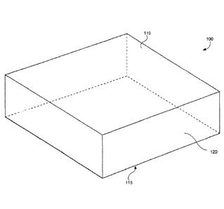
FIG. 1 is a schematic overview of an air mattress, in accordance with an
example
embodiment of the presently disclosed subject matter.
FIG. 2 is top view of an air mattress having a strip-based internal structure,
in accordance
an example embodiment of with the presently disclosed subject matter.
FIG. 3A is a side view of an air mattress having a strip-based internal
structure, in
accordance with an example embodiment of the presently disclosed subject
matter.
FIG. 3B is an end view of an air mattress having a strip-based internal
structure, in
accordance with an example embodiment of the presently disclosed subject
matter.
FIG. 4 is a perspective view of an air mattress having a strip-based internal
structure
including a detail view of a strip-based internal structure, in accordance
with an example
embodiment of the presently disclosed subject matter.
FIG. 5 is a perspective view of an air mattress having a strip-based internal
structure
including a detail view of a strip-based internal structure, in accordance
with an example
embodiment of the presently disclosed subject matter.
3
CA 02929485 2016-05-09
FIG. 6 is a perspective view of an air mattress having a mesh-based internal
structure
including a detail view of a mesh-based internal structure, in accordance with
an example
embodiment of the presently disclosed subject matter.
FIG. 7 is a perspective view of an internal portion of an air mattress having
a mesh-based
internal structure, showing attachment of the mesh-based internal structure to
the outer walls of
the air mattress in accordance with an example embodiment of the presently
disclosed subject
matter.
FIG. 8 is a schematic overview of an air mattress comprising various air
mattress
components, in accordance with an example embodiment of the presently
disclosed subject
matter.
DETAILED DESCRIPTION
Although certain embodiments of the disclosure are explained in detail, it is
to be
understood that other embodiments are contemplated. Accordingly, it is not
intended that the
disclosure is limited in its scope to the details of construction and
arrangement of components set
forth in the following description or illustrated in the drawings. Other
embodiments of the
disclosure are capable of being practiced or carried out in various ways.
Also, in describing the
embodiments, specific terminology will be resorted to for the sake of clarity.
It is intended that
each term contemplates its broadest meaning as understood by those skilled in
the art and
includes all technical equivalents which operate in a similar manner to
accomplish a similar
purpose.
It should also be noted that, as used in the specification and the appended
claims, the
singular forms "a," "an" and "the" include plural references unless the
context clearly dictates
otherwise. References to a composition containing "a" constituent is intended
to include other
constituents in addition to the one named. Also, in describing the preferred
embodiments,
terminology will be resorted to for the sake of clarity. It is intended that
each term contemplates
its broadest meaning as understood by those skilled in the art and includes
all technical
equivalents which operate in a similar manner to accomplish a similar purpose.
Herein, the use of terms such as "having," "has," "including," or "includes"
are open-
.. ended and are intended to have the same meaning as terms such as
"comprising" or "comprises"
and not preclude the presence of other structure, material, or acts.
Similarly, though the use of
4
CA 02929485 2016-05-09
terms such as "can" or "may" is intended to be open-ended and to reflect that
structure, material,
or acts are not necessary, the failure to use such terms is not intended to
reflect that structure,
material, or acts are essential. To the extent that structure, material, or
acts are presently
considered to be essential, they are identified as such.
It is also to be understood that the mention of one or more method steps does
not
preclude the presence of additional method steps or intervening method steps
between those
steps expressly identified. Moreover, although the term "step" may be used
herein to connote
different aspects of methods employed, the term should not be interpreted as
implying any
particular order among or between various steps herein disclosed unless and
except when the
order of individual steps is explicitly required.
The components described hereinafter as making up various elements of the
disclosure
are intended to be illustrative and not restrictive. Many suitable components
that would perform
the same or similar functions as the components described herein are intended
to be embraced
within the scope of the disclosure. Such other components not described herein
can include, but
are not limited to, for example, similar components that are developed after
development of the
presently disclosed subject matter.
The present disclosure is described in reference to an internal structure for
an air mattress
or airbed. In particular, the present disclosure relates to an internal
structure that comprises a
sheet or a plurality of connection strips that attach to connection points on
the top and bottom
surfaces of an air mattress. In some embodiments, the sheet or connection
strips may angle from
one connection point (e.g., on the bottom surface) toward another connection
point (e.g., on the
top surface). A single sheet can be attached to a plurality of connection
points, creating an
internal structure having a web-like effect. Further, in some embodiments,
multiple connection
strips can attach to a single connection point, thus creating an internal
structure having a web-
like effect. An internal structure having such a web-like configuration not
only helps the air
mattress maintain its intended shape and prevents over-inflation, it prevents
the top and bottom
surfaces from shearing or moving laterally relative to one another. Further,
because such an
internal structure is light-weight and comprises minimal material, it allows
the air mattress to be
easily stowed and transported.
Referring now to the figures, wherein like reference numerals represent like
parts
throughout the views, embodiments of the internal airbed structure will be
described in detail.
5
CA 02929485 2016-05-09
FIG. 1 is an overview of an air mattress 100. Air mattress 100 may vary in
size once
inflated based on the desired dimensions and/or number of users. For example,
air mattress 100
may be a twin, full, queen, or king size bed. In some embodiments, air
mattress 100 may be
constructed out of polyvinyl chloride ("PVC"). It is contemplated, however,
that other materials
such as other plastics or rubber may be used. Further, as shown in FIG. 1, the
air mattress 100
may comprise a top surface 110 and bottom surface 115 as well as side surfaces
(e.g., side
surface 120).
FIG. 2 is a top view of an embodiment of an air mattress 100 comprising an
internal
structure 200. As discussed, in some embodiments, an internal structure 200 of
an air mattress
100 may be included in the interior of the air mattress 100. The internal
structure 200 may help
the air mattress 100 achieve and maintain its intended shape once the air
mattress 100 is inflated.
Further, an internal structure 200 may prevent the air mattress 100 from over-
inflating.
Similarly, the internal structure 200 may prevent the top surface (e.g., top
surface 110) and the
bottom surface (e.g., bottom surface 115) from shearing (i.e., moving
laterally relative to each
other).
In some embodiments, an internal structure 200 may comprise a plurality of
connection
strips 210 (e.g., strips 210a, 210b) having a predetermined length that are
attached (i.e., joined,
connected, affixed) to one or more of the top surface 110 and bottom surface
115 of the air
mattress 100. In some embodiments, a connection strip 210 may be constructed
from PVC or
various other fiber, fabric, or film that is suitable for a particular
application. In some
embodiments, a connection strip 210 may be constructed from a single piece of
material (e.g.,
the connection strip 210 may be a single, continuous strip of PVC). In some
embodiments, a
connection strip 210 may be constructed from a collection (i.e., a plurality)
of materials, fibers,
or strings.
As shown in FIG. 2, in some embodiments, the air mattress 100 can be
transparent,
thereby providing a view of the plurality of connection strips 210 (e.g.,
connection strips 210a,
210b) comprising the internal structure 200. Further, the transparency of the
air mattress 100
provides a view of top surface connection points 215, as highlighted by dashed
box 220, which
includes top surface connection point 215a. Further, the transparency of the
air mattress 100
provides a view of bottom surface connection points 225, as highlighted by
dashed box 230,
which includes bottom surface connection point 225a. In some embodiments,
connection points
6
CA 02929485 2016-05-09
(e.g., top surface connection points 215 and bottom surface connection points
225) are on
opposing interior surfaces of the top surface 110 and bottom surface 115.
Accordingly, in such
embodiments, the connection points are on the interior of the air mattress
100. Further, in some
embodiments, connection strips 210 may attach directly to connection points
215 and 225. In
some embodiments, for example, a connection strip 210 may be welded to top and
bottom
surface attachment points 215, 225. Further, in some embodiments, a connection
strip 210 may
be glued, sewn, adhered, or otherwise attached to top and bottom surface
attachment points 215,
225.
As shown in FIG. 2, in some embodiments, a connection strip 210 may attach
between a
top surface connection point 215 and a bottom surface connection point 225. In
some
embodiments, when an air mattress 100 is inflated, as shown in FIG. 2, a
connection strip 210
may angle from top surface 110 toward bottom surface 115, or vice versa. For
example, as
shown in FIG. 2, connection strip 210c angles from bottom surface connection
point 225b
toward top surface connection point 215a. Similarly, as shown in FIG. 2,
connection strip 210d
angles from bottom surface connection point 225a toward top surface connection
point 215b,
according to some embodiments. As will be appreciated, when configured in the
manner
described and shown in FIG. 2, angled connection strips (e.g., connection
strip 210c and 210d)
may comprise an internal structure 200 with sufficient strength to prevent the
air mattress 100
from over-inflating and to prevent the top surface and bottom surface (e.g.,
110 and 115) from
moving laterally in relation to one another (i.e., shearing).
Further, in some embodiments, a plurality of connection strips 210 may connect
to a
particular top surface connection point 215 or bottom surface connection point
225. For
example, in some embodiments and as shown in FIG. 2, four connection strips
210e¨h attach to a
single connection point (i.e., top surface connection point 215c). It is
contemplated that in
various embodiments, any number of connection strips 210 could connect to a
particular
connection point (e.g., a top surface connection point 215 or bottom surface
connection point
225. As shown in FIG. 2, in configurations in which multiple connection strips
(e.g., 210e¨h)
attach to a single connection point (e.g., top surface connection point 215c),
and in which the
connection strips 210 angle from a top surface connection points 215 toward
bottom surface
connection points 225, and vice versa, the plurality of connection strips 210
may constitute an
internal structure 200 having a web-like configuration. According to some
embodiments, a
7
CA 02929485 2016-05-09
plurality of top surface connection points 215 may be spaced apart at
predetermined distances or
intervals, and a plurality of bottom surface connection points may also be
spaced apart at
predetermined distances or intervals. In some embodiments, a plurality of
bottom surface
connection points 225 may be located on the bottom surface 115 in positions
that are offset
relative to the locations of the plurality of top surface connection points
215 on the top surface
110. As will be appreciated, an internal structure 200 having a web-like
configuration may
further aid in helping an air mattress 100 maintain its intended shape and
prevent the air mattress
100 from becoming over-inflated. Further, an internal structure 200 having a
web-like
configuration may help prevent the top surface 110 and bottom surface 115 of
an air mattress
100 from shearing or moving laterally relative to one another.
As noted above, in some embodiments, a connection strip 210 may be constructed
from a
single piece of material. But, in some embodiments, a connection strip 210 may
comprise a
plurality of individual strips or strands. In some embodiments, each of the
plurality of individual
strips that comprise a connection strip may attach to the same top surface
connection point 215
and bottom surface connection point 225. In some embodiments, however, a
connection strip
210 may comprise attachment strips (or, alternatively, weld strips) at each
end of the connection
strip 210. An attachment strip may be a strip of material or a patch, that may
be used to affix a
portion of an internal structure 200 to a portion of the air mattress 100. For
example, an
attachment strip may be a strip of PVC that may be welded to a surface of the
air mattress 100.
In some embodiments, a portion of an internal structure 200, for example, a
portion of a
connection strip 210, may be sandwiched between an attachment strip and a
surface of the air
mattress 100 and the attachment strip may be welded to the surface of the air
mattress 100 to
secure the connection strip 210 to it. In such embodiments, the plurality of
individual strips or
strands comprising the connection strip 210 may be held in place by the
opposing attachment
strips, and the attachment strips may be affixed to the top and bottom surface
connection points
(i.e., 215 and 225). For example, in some embodiments, an attachment strip, a
portion of a
connection strip 210, and a portion of either the top surface 110 or bottom
surface 115 may be
welded together at a top surface connection point 215 or bottom surface
connection point 225.
FIG. 3A is a side view of an air mattress 100, according to some embodiments.
As
shown in FIG. 3A, a top surface 110 may comprise a plurality of top surface
connection points
315a, 315b as well as a plurality of bottom surface connection points 325a,
325b. In some
8
embodiments, a connection strip (e.g., connection strip 310a) may connect at
two connection
points (e.g., top surface connection point 315a and bottom surface connection
point 325a). As
shown in FIG. 3A, in some embodiments, a connection strip 310a may angle from
a top surface
connection point (e.g., 315a) toward a bottom surface connection point (e.g.,
325a). Similarly, in
some embodiments, a connection strip 310b may angle from a bottom surface
connection point
325b toward a top surface connection point 315b. As will be appreciated, such
a configuration of
connection strips (e.g., 310a, 310b) creates a web-like internal structure
200, which may help
prevent the top surface 110 and bottom surface 115 of the mattress 100 from
shearing.
Similarly, FIG. 3B is an end view of an air mattress 100, according to some
embodiments.
As shown in FIG. 3B, in some embodiments, a top surface 110 may comprise a
plurality of top
surface connection points (e.g., 315c), and a bottom surface 115 may comprise
a plurality of
bottom surface connection points (e.g., 325c), and connection strips (e.g.,
310c) may be attached
therebetween.
FIG. 4 is a perspective view of an air mattress 100, according to some
embodiments. As
shown in FIG 4, the air mattress 100 is transparent (as in FIG 2), thereby
providing a view of the
plurality of connection strips (e.g., 410a, 410b, 410c) comprising the
internal structure. Further,
FIG. 4 includes a close-up view 4A of various components of the internal
structure, according to
some embodiments. For example, close-up view 4A highlights top surface
connection point 415a
and bottom surface connection points 425a and 425b. Further, close-up view 4A
highlights
connection strip 410b, which is attached to top surface connection point 415a
and bottom surface
connection point 425a. Further, close-up view 4A highlights connection strip
410c, which is
attached to top surface connection point 415a and bottom surface connection
point 425b. As
shown in FIG. 4, in some embodiments, one or more connections strips 410 may
be configured to
extend from a top surface connection point 415 to a bottom surface connection
point 425 at a non-
right angle. Further, a plurality of connection strips 410 may extend out of
each of the top surface
connection points 415 and bottom surface connection points 425 to the opposing
surface. For
example, a connection point may have two, three, four, or more connection
strips 410 extending
away from it. According to some embodiments, each of these connection strips
410 may extend
and connect to a different connection point on the opposing surface. The
opposing surface of the
top surface connection points 415 may be the bottom surface 115 and the
opposing surface of the
bottom surface connection points 425 may be the top surface 110. According to
some
9
Date Recue/Date Received 2021-06-24
embodiments, where a connection point has a plurality of connection strips 410
extending out of
it, the plurality of connection strips may be configured to extend away from
the connection point
such that they are approximately equidistant from each adjacent connection
strip 410 when the
mattress is inflated.
FIG. 5 is a perspective view of an air mattress 100 comprising an internal
structure 500. In
some embodiments, an internal structure 500 of an air mattress 100 may be
included in the interior
of the air mattress 100 and may operate in a manner similar to internal
structure 200 described
above. For example, the internal structure 500 may help the air mattress 100
achieve and maintain
its intended shape once the air mattress 100 is inflated. Further, internal
structure 500 may prevent
the air mattress from over-inflating. Similarly, the internal structure 500
may prevent the top
surface (e.g., top surface 110) and the bottom surface (e.g., bottom surface
115) from shearing
(i.e., moving laterally relative to each other).
In some embodiments, an internal structure 500 may comprise a plurality of
connection
strips 510 having a predetermined length that are attached (i.e., joined,
connected, affixed) to one
or more of the top surface 110 and bottom surface 115 of the air mattress 100
In some
embodiments, a connection strip 510 may be constructed from PVC or various
other fiber, fabric,
or film that is suitable for a particular application. In some embodiments, a
connection strip 510
may be mesh, thread, or an equivalent material. A connection strip 510 may be
constructed from
a single piece of material (e.g., the connection strip 510 may be a single,
continuous strip of PVC,
mesh, thread, or an equivalent material), or a connection strip 510 may be
constructed from a
collection (i.e., a plurality) of' materials, fibers, or strings. According to
some embodiments, a
connection strip 510 may be attached to the top surface 110 and/or bottom
surface 115 at the top
surface connection point 515 and/or bottom surface connection point 525,
respectively, by
positioning the top surface connection point 515 and/or bottom surface
connection point 525
between an internal surface of air mattress 100 and a PVC strip and welding
them together.
As described above, in some embodiments, the air mattress 100 can be
transparent, thereby
providing a view of the plurality of connection strips 510 comprising internal
structure 500.
Further, the transparency of the air mattress 100 provides a view of top
surface connection points
515, which includes top surface connection point 515a. Further, the
transparency of the air
mattress 100 provides a view of bottom surface connection points 525, which
includes bottom
surface connection point 525a. In some embodiments, connection points (e.g.,
top surface
Date Recue/Date Received 2021-06-24
connection points 515 and bottom surface connection points 525) are on
opposing interior surfaces
of the top surface 110 and bottom surface 115. Accordingly, in such
embodiments, the connection
points are on the interior of the air mattress 100. Further, in some
embodiments, connection strips
510 may attach directly to top and bottom surface connection points 515 and
525 respectively. In
some embodiments, for example, a connection strip 610 may be welded to top and
bottom surface
connection points 515, 525. Further, in some embodiments, a connection strip
510 may be glued,
sewn, adhered, or otherwise attached to top and bottom surface connection
points 515, 525.
As shown in FIG. 5, in some embodiments, a connection strip 510 may attach
between a
top surface connection point 515 and a bottom surface connection point 525. In
some
embodiments, when air mattress 100 is inflated, as shown in FIG. 5, a
connection strip may angle
from top surface 110 toward bottom surface 115, or vice versa, in a "zig-zag"
fashion. For
example, as shown in FIG. 5, connection strip 510a angles from the bottom
surface connection
point 525a toward top surface connection point 515a. As shown in FIG. 5, the
connection strips
510 connecting bottom surface connection points 525 to top surface connection
points 515 may be
arranged in rows For example, in the embodiment shown in FIG 5, the internal
structure 500 is
made up of six rows of connection strips 510, wherein each row is indicated by
top surface
connection points 515a, 515b, 515c, 515d, 515e, and 515f, respectively.
According to some
embodiments, each row of connection strips 510 may be oriented to run parallel
to the length of
the air mattress 100. Alternatively, in some embodiments, each row of
connection strips 510 may
be oriented to run parallel to the width of the air mattress 100. And as a
further alternative, rows
of connection strips 510 can run in both directions. Although FIG. 5 shows six
rows of connection
strips 510, it will be understood that an internal structure 500 may be
comprised of any number of
rows of connection strips 510. As will be appreciated, when configured in the
manner described
and shown in FIG. 5, the rows of angled connection strips 510 may comprise an
internal structure
500 that prevents the air mattress 100 from over-inflating and that prevents
the top surface and
bottom surface (e.g., 110 and 115) from moving laterally in relation to one
another (i.e., shearing).
As noted above, in some embodiments, a connection strip 510 may be constructed
from a
single piece of material. But, in some embodiments, a connection strip 510 may
comprise a
plurality of individual strips or strands. In some embodiments, each of the
plurality of individual
strips that comprise a connection strip may attach to the same top surface
connection point 515
and bottom surface connection point 525. In some embodiments, however, a
connection strip 510
11
Date Recue/Date Received 2021-06-24
may comprise attachment strips (or, alternatively, weld strips) at each end of
the connection strip
510. In such embodiments, the plurality of individual strips or strands
comprising the connection
strip 510 may be held in place by the opposing attachment strips, and the
attachment strips may be
affixed to the top and bottom surface connection points (i.e., 515 and 525).
FIG. 6 is a perspective view of an air mattress 100 comprising an internal
structure 600
that is comprised of a single sheet of material. According to some
embodiments, the internal
structure 600 may be a continuous piece of material. In some embodiments, the
internal structure
may be a mesh structure 610 (which may also be referred to as a "mesh web" or
a "mesh sheet")
that includes one or more apertures forming a mesh. In some embodiments, a
mesh structure 610
may be made of a single piece of material including a plurality of apertures.
In some embodiments,
an internal structure 600 of an air mattress 100 may be included in the
interior of the air mattress
100 and may operate in a manner similar to internal structures 200, 500
described above. For
example, the internal structure 600 may help the air mattress 100 achieve and
maintain its intended
shape once the air mattress 100 is inflated. Further, internal structure 600
may prevent the air
mattress from over-inflating Similarly, the internal mesh structure 600 may
prevent the top
surface (e.g., top surface 110) and the bottom surface (e.g., bottom surface
115) from shearing
(i.e., moving laterally relative to each other). In some embodiments, the
outer edge of the internal
structure 600 may be attached to the inner surfaces of the side surfaces 120.
In some embodiments, a mesh structure 610 may be constructed from PVC or
various other
fiber, fabric, or film that is suitable for a particular application. In some
embodiments, a mesh
structure 610 may be constructed form a single piece of material (e.g., the
mesh structure 610 may
be a single, continuous piece of fiber). In some embodiments, a mesh structure
610 may be
constructed from a collection (i.e., plurality) of materials, fibers, or
strings.
As shown in FIG. 6, in some embodiments, a mesh structure 610 may attach to
the internal
surface of an air mattress 100 at various top surface connection points 615
and bottom surface
connection points 625. According to some embodiments, the top surface
connection points 615
and bottom surface connection points 625 may be located in positions similar
to those
12
Date Recue/Date Received 2021-06-24
CA 02929485 2016-05-09
shown with respect to internal structure 200 and creating a 3D web-like
structure as previously
described above. For example, according to some embodiments, a plurality of
top surface
connection points 615 may be spaced apart at predeteimined distances or
intervals, and a
plurality of bottom surface connection points may also be spaced apart at
predetermined
distances or intervals. In some embodiments, a plurality of bottom surface
connection points 625
may be located on the bottom surface 115 in positions that are offset relative
to the locations of
the plurality of top surface connection points 615 on the top surface 110.
Accordingly, in some
embodiments, when air mattress 100 is inflated, the mesh structure 610 may
take on a 3-
dimensional, approximately sinusoidal shape with top and bottom "humps"
extending in upwards
and/or downwards directions when the airbed is inflated, as shown in FIG. 6.
According to some
embodiments, the peak of each top hump may attach to the air mattress 100 at a
top connection
point 615 and the trough of each bottom hump may attach to the air mattress
100 at a bottom
connection point 625. As will be appreciated, an internal structure 600 having
a web-like
configuration may help prevent the top surface 110 and bottom surface 115 of
an air mattress
100 from shearing and moving laterally relative to one another.
As described above, a mesh structure 610 may attach (i.e., join, connect,
affix) to the top
surface 110 and bottom surface 115 of the air mattress 100. In some
embodiments, a mesh
structure 610 may attach to the air mattress 100 at one or more top surface
connection points 615
and one or more bottom surface connection points 625. In some embodiments,
portions of a
.. mesh structure 610 may be welded to top and bottom surface attachment
points 615, 625. In
some embodiments, portions of the mesh structure 610 may be attached to the
air mattress 100
with one or more attachment strips. For example, in some embodiments, an
attachment strip
may be used to secure a portion of a mesh structure 610 to a top surface
connection point 615 or
a bottom surface connection point 625. As shown in FIG. 7, according to some
embodiments.
portions of the mesh structure 610 may be attached to the air mattress 100
with one or more
attachment strips 705. For example, a top connection point 615 may be
sandwiched between an
attachment strip 705 and the top surface 110 and the three may be welded
together. Likewise, a
bottom surface connection point 625 may be sandwiched between an attachment
strip 705 and
the bottom surface 115 and the three may be welded together. According to some
embodiments,
.. an attachment strip 705 may be a PVC strip. Further, in some embodiments, a
mesh structure
13
CA 02929485 2016-05-09
610 may be glued, sewn, adhered, or otherwise attached to top and bottom
surface attachment
points 615, 625.
FIG. 8 is an embodiment of an air mattress 100 comprising a top surface 110,
bottom
surface 115, a plurality of side surfaces (e.g., side surface 120), and
various air mattress 100
components. Further, as shown in FIG. 8, in some embodiments, an air mattress
100 may
comprise a portable power source 810. In some embodiments, a portable power
source 810 may
be a battery and provide direct current. In other embodiments, portable power
source 810 may
include a motor or generator and provide alternating current. It is
contemplated that any portable
power source may be used. Further, a portable power source 810 may be housed
in a power
source housing (not shown) on air mattress 100 for convenient transport. In
some embodiments,
a portable power source 810 may comprise a power plug 815, which may be
attachable to
portable power source 810. In some embodiments, however, power plug 815 may be
used in lieu
of portable power source 810. Power plug 815 may include a variety of power
plugs, such as
those configured to plug into USB ports and 120V standard outlets. As will be
appreciated,
while a portable power source 810 may be used in outdoor and indoor locations,
a power plug
815 may be suited for indoor use when air mattress 100 is placed near an
electrical outlet.
In some embodiments, an air mattress may comprise an air control system 820,
which
may be used to control air flow and to inflate and deflate an air mattress
100. In some
embodiments, a portable power source 810 or a power plug 815 (or a combination
of both) may
provide power to an air control system 820. In some embodiments, an air
control system 820
may include an air intake component 822 and a controller 824. An air intake
component 822
may be configured to direct ambient air into the air mattress 100 during
mattress inflation and
direct air from the air mattress 100 during mattress deflation. In some
embodiments, the air
intake component 822 may comprise an outer seal that inhibits or allows the
flow of outside air
into the air control system 820. In some embodiments, the air intake component
822 also may
include an inner seal (not shown) that inhibits or allows the flow of internal
air between air
control system 820 and the air chamber (i.e., interior) of an air mattress
100.
In some embodiments, a controller 824 may be configured to receive user input
and
control the opening or closing of inner and outer seals and/or inflating and
deflating of the air
mattress 100 via the air control system 820. In some embodiments, the
controller 824 may
include one or more processors having memory. Also, in some embodiments, the
controller 824
14
CA 02929485 2016-05-09
may be configured to execute one or more operating modes. For example,
operating modes may
include inflation mode, deflation mode, air recirculation mode, and standby
mode. In some
embodiments, the controller 824 may include one or more electronic components
that allow a
user to switch between modes.
In some embodiments, inflation mode may begin when the controller 824 receives
user
input to inflate the air mattress 100. In some embodiments, inflation mode may
last until the
controller 824 receives additional user input to stop inflating the air
mattress 100. In some
embodiments, however, the controller 824 may automatically control the speed
and duration of
inflation based on a predetermined or user supplied air pressure for the air
in the air mattress 100.
During inflation mode, both the inner and outer seals may be open to allow
ambient air to flow
into the air mattress 100.
In some embodiments, deflation mode may begin when the controller 824 receives
user
input to deflate the air mattress 100. For example, in some embodiments,
deflation mode may
last until the controller 824 receives additional user input to stop deflating
the air mattress 100.
Further, in some embodiments, the controller 824 may automatically control the
speed and
duration of deflation based on a predetermined or user supplied air pressure
for the air in the air
mattress 100. During deflation mode, both the inner and outer seals may be
open to allow
ambient air to flow out of the air mattress 100.
According to some embodiments, an air recirculation mode may begin when the
controller 824 receives user input to circulate air within air mattress 100.
In doing so, the
controller 824 may direct the outer seal to close while the inner seal remains
open, thus allowing
air to enter the air intake component 822, but not escape the air mattress
100. According to some
embodiments, circulating air within an air mattress 100 may cause a vibrating
or massaging
pulse on the surface of the air mattress 100 and/or adjust air pressure via
air control system 820.
In some embodiments, air recirculation mode may last until the controller 824
receives additional
user input to stop circulating air within the air mattress 100. Also, in some
embodiments, the
controller 824 may automatically control the time duration and/or interval to
recirculate air
within the air mattress 100.
In some embodiments, a standby mode may occur when the controller 824 receives
power from portable power source 810 and/or power plug 815 and is not placed
in another mode.
For example, the controller 824 may operate in standby mode before receiving
user input. In
CA 02929485 2016-05-09
some embodiments, the controller 824 may also direct the inner seal to close
to inhibit air
recirculation. Also, in some embodiments, the controller 824 may direct the
inner seal to remain
open. It is contemplated that the air mattress 100 may only include the outer
seal and not the
inner seal, according to some embodiments.
In some embodiments, an air mattress 100 may comprise an air release valve
840.
According to some embodiments, an air release valve 840 may be configured to
inhibit the flow
of air out of the air mattress 100 when the air release valve 840 is in a
closed position and allow
air flow out of air mattress 100 when the air release valve 840 is in an open
position. In some
embodiments, an air release valve 840 may move from the closed position to an
open position
.. when the air pressure inside an air mattress 100 exceeds a predetermined
threshold. In such
embodiments, the air release valve 840 may serve as a safety valve to prevent
damage to the air
mattress 100 from over-inflation. In some embodiments, an air release valve
840 may comprise
a removable plug that may be removed when a user desires to deflate the air
mattress 100. In
some embodiments, an air release valve 840 may be constructed out of polyvinyl
chloride
("PVC"). It is contemplated, however, that other materials such as plastics or
rubber may be
used.
While the present disclosure has been described in connection with a plurality
of
exemplary aspects, as illustrated in the various figures and discussed above,
it is understood that
other similar aspects can be used or modifications and additions can be made
to the described
.. aspects for performing the same function of the present disclosure without
deviating therefrom.
For example, in various aspects of the disclosure, methods and compositions
were described
according to aspects of the presently disclosed subject matter. But, other
equivalent methods or
composition to these described aspects are also contemplated by the teachings
herein. Therefore,
the present disclosure should not be limited to any single aspect, but rather
construed in breadth
and scope in accordance with the appended claims.
16