Note: Descriptions are shown in the official language in which they were submitted.
CA 02929572 2016-05-03
WO 2015/095411
PCT/US2014/070984
1
AUTOMATED EXPERIMENTATION PLATFORM
CROSS-REFERENCE TO RELATED APPLICATION
This application claims the benefit of Provisional Application No. 61/916,888,
filed December 17, 2013.
TECHNICAL FIELD
The present document is related to computational systems and, in particular,
to
an automated experimentation platform that provides a visual integrated
development
environment which allows a user to construct and execute data-driven
workflows.
BACKGROUND
Data processing has evolved, over the past 60 years, from relying on largely
ad hoc program that use basic operating-system functionality and hand-coded
data-processing
routines to an enormous variety of different types of higher-level automated
data-processing
environments, including various generalized data-processing applications and
utilities and
tools associated with database management systems. However, many of these
automated
data-processing systems are associated with significant constraints, including
constraints with
regard to specification of data-processing procedures, data models, data
types, and other such
constraints. Moreover, most automated systems still involve a large amount of
problem-
specific coding to specify data-processing steps as well as data
transformations needed to
direct data to particular types of functionality associated with particular
interfaces. As a
result, those who design and develop data-processing systems and tools as well
as those who
use them continue to seek new data-processing systems and fimctionalities.
CA 02929572 2016-05-03
WO 2015/095411
PCT/US2014/070984
2
SUMMARY
The present document is directed to an automated experimentation platform
that provides a visual integrated development environment ("IDE") that allpws
a user to
construct and execute various types of data-driven workflows. The
automated
experimentation platform includes back-end components that include API
servers, a catalog,
a cluster-management component, and execution-cluster nodes. Workflows are
visually
represents as directed acyclic graphs and texturally encoded. The workflows
are transformed
into jobs that are distributed for execution to the execution-cluster nodes.
BRIEF DESCRIPTION OF THE DRAWINGS
Figure 1 shows an example workflow created by a user of the currently
disclosed automated experimentation platform.
Figure 2 illustrates how, following a run of the experiment shown in Figure 1,
a user can modify the experiment by substituting, for input data set 102 in
Figure 1, a new
input data set 202.
Figure 3 shows a dashboard view of the second workflow, shown in Figure 2.
Figure 4 provides a general architectural diagram for various types of
computers.
Figure 5 illustrates an Internet-connected distributed computer system.
Figure 6 illustrates cloud computing.
Figure 7 illustrates generalized hardware and software components of a general-
purpose computer system, such as a general-purpose computer system having an
architecture
similar to that shown in Figure 1.
Figures 8A-B illustrate two types of virtual machine and virtual-machine
execution environments.
Figure 9 illustrates electronic communications between a client and server
computer.
Figure 10 illustrates the role of resources in RESTful APIs.
Figures 11A-D illustrate four basic verbs, or operations, provided by the
HTTP application-layer protocol used in RESTful applications.
Figure 12 illustrates the main components of the scientific-workflow system to
which the current document is directed.
CA 02929572 2016-05-03
WO 2015/095411
PCT/US2014/070984
3
Figures 13A-E illustrate the JSON encoding of a relatively simple six-node
experiment DAG.
Figures 14A-D illustrate the metadata that is stored in the catalog service
(1226 in Figure 12).
Figures 15A-I provide an example of an experiment layout DAG
corresponding to an experiment DAG, such as the experiment DAG discussed above
with
reference to Figures 13C-D.
Figures 16A-I illustrate the process of experiment design and execution within
the scientific-workflow system.
Figures 17A-B show a sample visual representation of an experiment DAG
and the corresponding JSON encoding of the experiment DAG.
Figures 18A-G illustrate the activities carried out by the API-server
component (1608 in Figure 16A) of the scientific-workflow-system back end
following
submission of an experiment for execution by a user via a front-end experiment-
dashboard
application.
Figure 19 provides a control-flow diagram for the routine "cluster manager"
which executes on the cluster-manager component of the scientific-workflow-
system back
end to distribute jobs to execution cluster nodes for execution.
Figure 20 provides a control-flow diagram for the routine "pinger."
Figure 21 provides a control-flow diagram for the routine "executor" that
launches execution of jobs on an execution-cluster node.
CA 02929572 2016-05-03
WO 2015/095411
PCT/US2014/070984
4
DETAILED DESCRIPTION
The present document is directed to an automated experimentation platfami
that allows users to conduct data-driven experiments. The experiments are
complex
computational tasks, and are assembled as workflows by a user through a visual
IDE. The
model underlying this visual IDE and the automated experimentation platform,
in general,
includes three basic entities: (1) input data sets; (2) generated data sets,
including
intermediate and output data sets; and (3) execution modules with
configurations. Once a
workflow is graphically constructed, the automated experimentation platform
executes the
workflow and produces output data sets. Configured execution modules are
converted, by a
run-time instance of an experiment, into jobs. These jobs are executed and
monitored by the
automated experimentation platform, and can be executed either locally, on the
same
computer system in which the automated experimentation platform is
incorporated, or
remotely, on remote computer systems. In other words, execution of workflows
may map to
distributed computing components. In
certain implementations, the automated
experimentation platform is, itself, distributed across multiple computer
systems. The
automated experimentation platform can run multiple jobs and multiple
workflows, in
parallel, and includes sophisticated logic for avoiding redundant generation
of datasets and
redundant execution of jobs, when needed datasets have already been generated
and
catalogued by the automated experimentation platform.
The execution modules can be written in any of a very wide variety of
different languages, including python, java, hive, mysql, scala, spark, and
other programming
languages. The
automated experimentation platform automatically handles data
transformations needed for input of data into various types of execution
modules. The
automated execution platform additionally includes versioning components that
recognize
and catalog different versions of experiments, implemented as workflows,
execution
modules, and data sets, so that an entire history of experimentation can be
accessed by users
for re-use and re-execution as well as for building new experiments based on
previous
experiments, execution modules, and data sets.
The automated experimentation platform provides dashboard capabilities that
allow users to upload and download execution modules from and to a local
machine as well
as to upload and download input, intermediate, and output data sets from and
to a local
machine. In addition, a user can search for execution modules and data sets by
name, by
CA 02929572 2016-05-03
WO 2015/095411
PCT/US2014/070984
values for one or more attributes associated with the execution modules and
user data sets,
and by description. Existing workflows can be cloned and portions of existing
workflows
can be extracted and modified in order to create new workflows for new
experiments. The
visual workflow-creation facilities provided by the automated experimentation
platform
vastly increases user productivity by allowing users to quickly design and
execute complex
data-driven processing tasks. In addition, because the automated
experimentation platform
can identify potential duplication of execution and duplicate data,
significant computational
efficiency is obtained versus hand-coded or less intelligent automated data-
processing
systems. In addition, the automated experimentation platform allows user to
collaborate, as
teams, to publish, share, and cooperatively create experiments, workflows,
data sets, and
execution modules.
Figure 1 shows an example workflow created by a user of the currently
disclosed automated experimentation platfoini. Figure 1, and Figures 2-3,
discussed below,
show the workflow as the workflow would be displayed to a user through the
graphical user
interface of the visual IDE provided by the automated experimentation
platform. In Figure 1,
the workflow 100 includes two input data sets 102 and 104. The first input
data set 102 is
input to a first execution module 106 which, in the illustrated example,
produces an
intermediate data set, represented by circle 108, that consists of results
sets of a Monte-Carlo
simulation. Intermediate data set 108 is then input to a second execution
module 110 that
produces an output data set 112. The second input data set 104 is processed by
a third
execution module 114 which generates a second intermediate data set 116, in
this case a large
file continuing the results of a very large number of Monte-Carlo simulations.
The second
intermediate data set 116 is input, along with input data set 102, to
execution module 106.
As shown in Figure 2, following a run of the experiment shown in Figure 1, a
user can modify the experiment by substituting, for input data set 102 in
Figure 1, a new
input data set 202. The user can then execute the new workflow to produce a
new output data
set 204. In this case, because there were no changes to the second input data
set 104 and
third execution module 114, execution of the second workflow does not involve
re-input of
the second input data set 104 to the third execution module 114 and execution
of the third
execution module 114. Instead, the intelinediate data set 116 previously
produced by
execution of the third execution module can be retrieved from a catalogue of
previously
produced intermediate data sets and input to the second execution module 106
during a run of
CA 02929572 2016-05-03
WO 2015/095411
PCT/US2014/070984
6
the second workflow shown in Figure 2. Note that the three execution modules
106, 110, and
114 may have been programmed in different languages and may be run on
different physical
computer systems. Note also that the automated experimentation platform is
responsible for
determining the types of the input data sets 102 and 104 and ensuring that,
when necessary,
these data sets are appropriately modified in order to have the proper format
and data types
needed by the execution modules 106 and 114, into which they are input during
execution of
the workflow.
Figure 3 shows a dashboard view of the second workflow, shown in Figure 2.
As can be seen in Figure 3, the workflow is displayed visually to the user in
a workflow-
display panel 302. In addition, the dashboard provides a variety of tools with
corresponding
input and manipulation features 304-308 as well as additional display windows
310 and 312
that display information relevant to various tasks and operations carried out
by a user using
the input and manipulation features.
In two following subsections, overviews of the hardware platforms and
RESTful communications used in a described implementation of the automated
experimentation platform to which the current document is directed. A final
subsection
described an implementation of the automated experimentation platform to which
the current
document is directed, referred to as the "scientific-workflow system."
Computer Hardware, Distributed Computational Systems, and Virtualization
The temi "abstraction" is not, in any way, intended to mean or suggest an
abstract idea or concept. Computational abstractions are tangible, physical
interfaces that are
implemented, ultimately, using physical computer hardware, data-storage
devices, and
communications systems. Instead, the teim "abstraction" refers, in the current
discussion, to
a logical level of functionality encapsulated within one or more concrete,
tangible,
physically-implemented computer systems with defined interfaces through which
electronically-encoded data is exchanged, process execution launched, and
electronic services
are provided. Interfaces may include graphical and textual data displayed on
physical display
devices as well as computer programs and routines that control physical
computer processors
to carry out various tasks and operations and that are invoked through
electronically
implemented application programming interfaces ("APIs") and other
electronically
CA 02929572 2016-05-03
WO 2015/095411
PCT/US2014/070984
7
implemented interfaces. There is a tendency among those unfamiliar with modern
technology and science to misinterpret the terms "abstract" and "abstraction,"
when used to
describe certain aspects of modem computing. For example, one frequently
encounters
assertions that, because a computational system is described in terms of
abstractions,
functional layers, and interfaces, the computational system is somehow
different from a
physical machine or device. Such allegations are unfounded. One only needs to
disconnect a
computer system or group of computer systems from their respective power
supplies to
appreciate the physical, machine nature of complex computer technologies. One
also
frequently encounters statements that characterize a computational technology
as being "only
software," and thus not a machine or device. Software is essentially a
sequence of encoded
symbols, such as a printout of a computer program or digitally encoded
computer instructions
sequentially stored in a file on an optical disk or within an
electromechanical mass-storage
device. Software alone can do nothing. It is only when encoded computer
instructions are
loaded into an electronic memory within a computer system and executed on a
physical
processor that so-called "software implemented" functionality is provided. The
digitally
encoded computer instructions are an essential and physical control component
of processor-
controlled machines and devices, no less essential and physical than a cam-
shaft control
system in an internal-combustion engine. Multi-cloud aggregations, cloud-
computing
services, virtual-machine containers and virtual machines, communications
interfaces, and
many of the other topics discussed below are tangible, physical components of
physical,
electro-optical-mechanical computer systems.
Figure 4 provides a general architectural diagram for various types of
computers. Computers within cloud-computing facilities may be described by the
general
architectural diagram shown in Figure 4, for example. The computer system
contains one or
multiple central processing units ("CPUs") 402-405, one or more electronic
memories 408
interconnected with the CPUs by a CPU/memory-subsystem bus 410 or multiple
busses, a
first bridge 412 that interconnects the CPU/memory-subsystem bus 410 with
additional
busses 414 and 416, or other types of high-speed interconnection media,
including multiple,
high-speed serial interconnects. These busses or serial interconnections, in
turn, connect the
CPUs and memory with specialized processors, such as a graphics processor 418,
and with
one or more additional bridges 420, which are interconnected with high-speed
serial links or
with multiple controllers 422-427, such as controller 427, that provide access
to various
CA 02929572 2016-05-03
WO 2015/095411
PCT/US2014/070984
8
different types of mass-storage devices 428, electronic displays, input
devices, and other such
components, subcomponents, and computational resources. It should be noted
that computer-
readable data-storage devices include optical and electromagnetic disks,
electronic memories,
and other physical data-storage devices. Those familiar with modem science and
technology
appreciate that electromagnetic radiation and propagating signals do not store
data for
subsequent retrieval, and can transiently "store" only a byte or less of
information per mile,
far less information than needed to encode even the simplest of routines.
Of course, there are many different types of computer-system architectures
that differ from one another in the number of different memories, including
different types of
hierarchical cache memories, the number of processors and the connectivity of
the processors
with other system components, the number of internal communications busses and
serial
links, and in many other ways. However, computer systems generally execute
stored
programs by fetching instructions from memory and executing the instructions
in one or more
processors. Computer systems include general-purpose computer systems, such as
personal
computers ("PCs"), various types of servers and workstations, and higher-end
mainframe
computers, but may also include a plethora of various types of special-purpose
computing
devices, including data-storage systems, communications routers, network
nodes, tablet
computers, and mobile telephones.
Figure 5 illustrates an Internet-connected distributed computer system. As
communications and networking technologies have evolved in capability and
accessibility,
and as the computational bandwidths, data-storage capacities, and other
capabilities and
capacities of various types of computer systems have steadily and rapidly
increased, much of
modem computing now generally involves large distributed systems and computers
interconnected by local networks, wide-area networks, wireless communications,
and the
Internet. Figure 5 shows a typical distributed system in which a large number
of PCs 502-
505, a high-end distributed mainframe system 510 with a large data-storage
system 512, and
a large computer center 514 with large numbers of rack-mounted servers or
blade servers all
interconnected through various communications and networking systems that
together
comprise the Internet 516. Such distributed computing systems provide diverse
arrays of
functionalities. For example, a PC user sitting in a home office may access
hundreds of
millions of different web sites provided by hundreds of thousands of different
web servers
CA 02929572 2016-05-03
WO 2015/095411
PCT/US2014/070984
9
throughout the world and may access high-computational-bandwidth computing
services
from remote computer facilities for running complex computational tasks.
Figure 6 illustrates cloud computing. In the recently developed cloud-
computing paradigm, computing cycles and data-storage facilities are provided
to
organizations and individuals by cloud-computing providers. In
addition, larger
organizations may elect to establish private cloud-computing facilities in
addition to, or
instead of, subscribing to computing services provided by public cloud-
computing service
providers. In Figure 6, a system administrator for an organization, using a PC
602, accesses
the organization's private cloud 604 through a local network 606 and private-
cloud interface
608 and also accesses, through the Internet 610, a public cloud 612 through a
public-cloud
services interface 614. The administrator can, in either the case of the
private cloud 604 or
public cloud 612, configure virtual computer systems and even entire virtual
data centers and
launch execution of application programs on the virtual computer systems and
virtual data
centers in order to carry out any of many different types of computational
tasks. As one
example, a small organization may configure and ran a virtual data center
within a public
cloud that executes web servers to provide an e-commerce interface through the
public cloud
to remote customers of the organization, such as a user viewing the
organization's e-
commerce web pages on a remote user system 616.
Cloud-computing facilities are intended to provide computational bandwidth
and data-storage services much as utility companies provide electrical power
and water to
consumers. Cloud computing provides enormous advantages to small organizations
without
the resources to purchase, manage, and maintain in-house data centers. Such
organizations
can dynamically add and delete virtual computer systems from their virtual
data centers
within public clouds in order to track computational-bandwidth and data-
storage needs, rather
than purchasing sufficient computer systems within a physical data center to
handle peak
computational-bandwidth and data-storage demands. Moreover, small
organizations can
completely avoid the overhead of maintaining and managing physical computer
systems,
including hiring and periodically retraining information-technology
specialists and
continuously paying for operating-system and database-management-system
upgrades.
Furthermore, cloud-computing interfaces allow for easy and straightforward
configuration of
virtual computing facilities, flexibility in the types of applications and
operating systems that
CA 02929572 2016-05-03
WO 2015/095411
PCT/US2014/070984
can be configured, and other finictionalities that are useful even for owners
and
administrators of private cloud-computing facilities used by a single
organization.
Figure 7 illustrates generalized hardware and software components of a
general-purpose computer system, such as a general-purpose computer system
having an
architecture similar to that shown in Figure 1. The computer system 700 is
often considered
to include three fundamental layers: (1) a hardware layer or level 702; (2) an
operating-
system layer or level 704; and (3) an application-program layer or level 706.
The hardware
layer 702 includes one or more processors 708, system memory 710, various
different types
of input-output ('I/O') devices 710 and 712, and mass-storage devices 714. Of
course, the
hardware level also includes many other components, including power supplies,
internal
communications links and busses, specialized integrated circuits, many
different types of
processor-controlled or microprocessor-controlled peripheral devices and
controllers, and
many other components. The operating system 704 interfaces to the hardware
level 702
through a low-level operating system and hardware interface 716 generally
comprising a set
of non-privileged computer instructions 718, a set of privileged computer
instructions 720, a
set of non-privileged registers and memory addresses 722, and a set of
privileged registers
and memory addresses 724. In general, the operating system exposes non-
privileged
instructions, non-privileged registers, and non-privileged memory addresses
726 and a
system-call interface 728 as an operating-system interface 730 to application
programs 732-
736 that execute within an execution environment provided to the application
programs by
the operating system. The operating system, alone, accesses the privileged
instructions,
privileged registers, and privileged memory addresses. By reserving access to
privileged
instructions, privileged registers, and privileged memory addresses, the
operating system can
ensure that application programs and other higher-level computational entities
cannot
interfere with one another's execution and cannot change the overall state of
the computer
system in ways that could deleteriously impact system operation. The operating
system
includes many internal components and modules, including a scheduler 742,
memory
management 744, a file system 746, device drivers 748, and many other
components and
modules. To a certain degree, modern operating systems provide numerous levels
of
abstraction above the hardware level, including virtual memory, which provides
to each
application program and other computational entities a separate, large, linear
memory-address
space that is mapped by the operating system to various electronic memories
and mass-
CA 02929572 2016-05-03
WO 2015/095411
PCT/US2014/070984
11
storage devices. The scheduler orchestrates interleaved execution of various
different
application programs and higher-level computational entities, providing to
each application
program a virtual, stand-alone system devoted entirely to the application
program. From the
application program's standpoint, the application program executes
continuously without
concern for the need to share processor resources and other system resources
with other
application programs and higher-level computational entities. The device
drivers abstract
details of hardware-component operation, allowing application programs to
employ the
system-call interface for transmitting and receiving data to and from
communications
networks, mass-storage devices, and other I/O devices and subsystems. The file
system 736
facilitates abstraction of mass-storage-device and memory resources as a high-
level, easy-to-
access, file-system interface. Thus, the development and evolution of the
operating system
has resulted in the generation of a type of multi-faceted virtual execution
environment for
application programs and other higher-level computational entities.
While the execution environments provided by operating systems have proved
to be an enorrnously successful level of abstraction within computer systems,
the operating-
system-provided level of abstraction is nonetheless associated with
difficulties and challenges
for developers and users of application programs and other higher-level
computational
entities. One difficulty arises from the fact that there are many different
operating systems
that run within various different types of computer hardware. In many cases,
popular
application programs and computational systems are developed to iun on only a
subset of the
available operating systems, and can therefore be executed within only a
subset of the various
different types of computer systems on which the operating systems are
designed to run.
Often, even when an application program or other computational system is
ported to
additional operating systems, the application program or other computational
system can
nonetheless run more efficiently on the operating systems for which the
application program
or other computational system was originally targeted. Another difficulty
arises from the
increasingly distributed nature of computer systems. Although distributed
operating systems
are the subject of considerable research and development efforts, many of the
popular
operating systems are designed primarily for execution on a single computer
system. In
many cases, it is difficult to move application programs, in real time,
between the different
computer systems of a distributed computer system for high-availability, fault-
tolerance, and
load-balancing purposes. The problems are even greater in heterogeneous
distributed
CA 02929572 2016-05-03
WO 2015/095411
PCT/US2014/070984
12
computer systems which include different types of hardware and devices running
different
types of operating systems. Operating systems continue to evolve, as a result
of which
certain older application programs and other computational entities may be
incompatible with
more recent versions of operating systems for which they are targeted,
creating compatibility
issues that are particularly difficult to manage in large distributed systems.
For all of these reasons, a higher level of abstraction, referred to as the
"virtual
machine," has been developed and evolved to further abstract computer hardware
in order to
address many difficulties and challenges associated with traditional computing
systems,
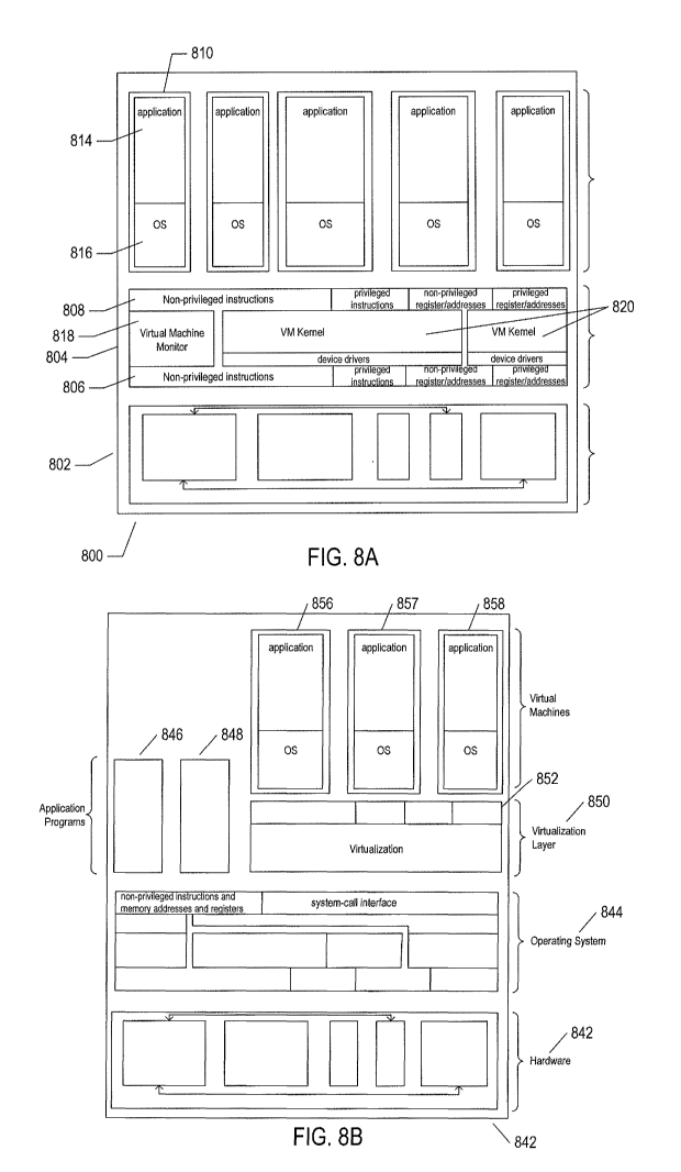
including the compatibility issues discussed above. Figures 8A-B illustrate
two types of
virtual machine and virtual-machine execution environments. Figures 8A-B use
the same
illustration conventions as used in Figure 7. Figure 8A shows a first type of
virtualization.
The computer system 800 in Figure 8A includes the same hardware layer 802 as
the hardware
layer 702 shown in Figure 7. However, rather than providing an operating
system layer
directly above the hardware layer, as in Figure 7, the virtualized computing
environment
illustrated in Figure 8A features a virtualization layer 804 that interfaces
through a
virtualization-layer/hardware-layer interface 806, equivalent to interface 716
in Figure 7, to
the hardware. The virtualization layer provides a hardware-like interface 808
to a number of
virtual machines, such as virtual machine 810, executing above the
virtualization layer in a
virtual-machine layer 812. Each virtual machine includes one or more
application programs
or other higher-level computational entities packaged together with an
operating system,
referred to as a "guest operating system,'' such as application 814 and guest
operating system
816 packaged together within virtual machine 810. Each virtual machine is thus
equivalent
to the operating-system layer 704 and application-program layer 706 in the
general-purpose
computer system shown in Figure 7. Each guest operating system within a
virtual machine
interfaces to the virtualization-layer interface 808 rather than to the actual
hardware interface
806. The virtualization layer partitions hardware resources into abstract
virtual-hardware
layers to which each guest operating system within a virtual machine
interfaces. The guest
operating systems within the virtual machines, in general, are unaware of the
virtualization
layer and operate as if they were directly accessing a true hardware
interface. The
virtualization layer ensures that each of the virtual machines currently
executing within the
virtual environment receive a fair allocation of underlying hardware resources
and that all
virtual machines receive sufficient resources to progress in execution. The
virtualization-
CA 02929572 2016-05-03
WO 2015/095411
PCT/US2014/070984
13
layer interface 808 may differ for different guest operating systems. For
example, the
virtualization layer is generally able to provide virtual hardware interfaces
for a variety of
different types of computer hardware. This allows, as one example, a virtual
machine that
includes a guest operating system designed for a particular computer
architecture to run on
hardware of a different architecture. The number of virtual machines need not
be equal to the
number of physical processors or even a multiple of the number of processors.
The virtualization layer includes a virtual-machine-monitor module 818
("VMM") that virtualizes physical processors in the hardware layer to create
virtual
processors on which each of the virtual machines executes. For execution
efficiency, the
virtualization layer attempts to allow virtual machines to directly execute
non-privileged
instructions and to directly access non-privileged registers and memory.
However, when the
guest operating system within a virtual machine accesses virtual privileged
instructions,
virtual privileged registers, and virtual privileged memory through the
virtualization-layer
interface 808, the accesses result in execution of virtualization-layer code
to simulate or
emulate the privileged resources. The virtualization layer additionally
includes a kernel
module 820 that manages memory, communications, and data-storage machine
resources on
behalf of executing virtual machines ("VM kernel"). The VM kernel, for
example, maintains
shadow page tables on each virtual machine so that hardware-level virtual-
memory facilities
can be used to process memory accesses. The VM kernel additionally includes
routines that
implement virtual communications and data-storage devices as well as device
drivers that
directly control the operation of underlying hardware communications and data-
storage
devices. Similarly, the VM kernel virtualizes various other types of I/O
devices, including
keyboards, optical-disk drives, and other such devices. The virtualization
layer essentially
schedules execution of virtual machines much like an operating system
schedules execution
of application programs, so that the virtual machines each execute within a
complete and
fully functional virtual hardware layer.
Figure 8B illustrates a second type of virtualization. In Figure 8B, the
computer system 840 includes the same hardware layer 842 and software layer
844 as the
hardware layer 702 shown in Figure 7. Several application programs 846 and 848
are shown
running in the execution environment provided by the operating system. In
addition, a
virtualization layer 850 is also provided, in computer 840, but, unlike the
virtualization layer
804 discussed with reference to Figure 8A, virtualization layer 850 is layered
above the
CA 02929572 2016-05-03
WO 2015/095411
PCT/US2014/070984
14
operating system 844, referred to as the "host OS," and uses the operating
system interface to
access operating-system-provided functionality as well as the hardware. The
virtualization
layer 850 comprises primarily a VMM and a hardware-like interface 852, similar
to
hardware-like interface 808 in Figure 8A. The virtualization-layer/hardware-
layer interface
852, equivalent to interface 716 in Figure 7, provides an execution
environment for a number
of virtual machines 856-858, each including one or more application programs
or other
higher-level computational entities packaged together with a guest operating
system.
In Figures 8A-B, the layers are somewhat simplified for clarity of
illustration.
For example, portions of the virtualization layer 850 may reside within the
host-operating-
system kernel, such as a specialized driver incorporated into the host
operating system to
facilitate hardware access by the virtualization layer.
It should be noted that virtual hardware layers, virtualization layers, and
guest
operating systems are all physical entities that are implemented by computer
instructions
stored in physical data-storage devices, including electronic memories, mass-
storage devices,
optical disks, magnetic disks, and other such devices. The term "virtual" does
not, in any
way, imply that virtual hardware layers, virtualization layers, and guest
operating systems are
abstract or intangible. Virtual hardware layers, virtualization layers, and
guest operating
systems execute on physical processors of physical computer systems and
control operation
of the physical computer systems, including operations that alter the physical
states of
physical devices, including electronic memories and mass-storage devices. They
are as
physical and tangible as any other component of a computer since, such as
power supplies,
controllers, processors, busses, and data-storage devices.
RESTful APIs
Electronic communications between computer systems generally comprises
packets of information, referred to as datagrams, transferred from client
computers to server
computers and from server computers to client computers. In many
cases, the
communications between computer systems is commonly viewed from the relatively
high
level of an application program which uses an application-layer protocol for
information
transfer. However, the application-layer protocol is implemented on top of
additional layers,
including a transport layer, Internet layer, and link layer. These layers are
commonly
implemented at different levels within computer systems. Each layer is
associated with a
CA 02929572 2016-05-03
WO 2015/095411
PCT/US2014/070984
protocol for data transfer between corresponding layers of computer systems.
These layers of
protocols are commonly referred to as a "protocol stack." In Figure 9, a
representation of a
common protocol stack 930 is shown below the interconnected server and client
computers
904 and 902. The layers are associated with layer numbers, such as layer
number "1" 932
associated with the application layer 934. These same layer numbers are used
in the
depiction of the interconnection of the client computer 902 with the server
computer 904,
such as layer number "1" 932 associated with a horizontal dashed line 936 that
represents
interconnection of the application layer 912 of the client computer with the
applications/services layer 914 of the server computer through an application-
layer protocol.
A dashed line 936 represents interconnection via the application-layer
protocol in Figure 9,
because this interconnection is logical, rather than physical. Dashed-line 938
represents the
logical interconnection of the operating-system layers of the client and
server computers via a
transport layer. Dashed line 940 represents the logical interconnection of the
operating
systems of the two computer systems via an Internet-layer protocol. Finally,
links 906 and
908 and cloud 910 together represent the physical communications media and
components
that physically transfer data from the client computer to the server computer
and from the
server computer to the client computer. These physical communications
components and
media transfer data according to a link-layer protocol. In Figure 9, a second
table 942 aligned
with the table 930 that illustrates the protocol stack includes example
protocols that may be
used for each of the different protocol layers. The hypertext transfer
protocol ("HTTP") may
be used as the application-layer protocol 944, the transmission control
protocol ("TCP") 946
may be used as the transport-layer protocol, the Internet protocol 948 ("IP")
may be used as
the Internet-layer protocol, and, in the case of a computer system
interconnected through a
local Ethernet to the Internet, the Ethernet/IEEE 802.3u protocol 950 may be
used for
transmitting and receiving information from the computer system to the complex
communications components of the Internet. Within cloud 910, which represents
the
Internet, many additional types of protocols may be used for transferring the
data between the
client computer and server computer.
Consider the sending of a message, via the HTTP protocol, from the client
computer to the server computer. An application program generally makes a
system call to
the operating system and includes, in the system call, an indication of the
recipient to whom
the data is to be sent as well as a reference to a buffer that contains the
data. The data and
CA 02929572 2016-05-03
WO 2015/095411
PCT/US2014/070984
16
other information are packaged together into one or more H riP datagrams, such
as datagram
952. The datagram may generally include a header 954 as well as the data 956,
encoded as a
sequence of bytes within a block of memory. The header 954 is generally a
record composed
of multiple byte-encoded fields. The call by the application program to an
application-layer
system call is represented in Figure 9 by solid vertical arrow 958. The
operating system
employs a transport-layer protocol, such as TCP, to transfer one or more
application-layer
datagrams that together represent an application-layer message. In general,
when the
application-layer message exceeds some threshold number of bytes, the message
is sent as
two or more transport-layer messages. Each of the transport-layer messages 960
includes a
transport-layer-message header 962 and an application-layer datagram 952. The
transport-
layer header includes, among other things, sequence numbers that allow a
series of
application-layer datagrams to be reassembled into a single application-layer
message. The
transport-layer protocol is responsible for end-to-end message transfer
independent of the
underlying network and other communications subsystems, and is additionally
concerned
with error control, segmentation, as discussed above, flow control, congestion
control,
application addressing, and other aspects of reliable end-to-end message
transfer. The
transport-layer datagrams are then forwarded to the Internet layer via system
calls within the
operating system and are embedded within Internet-layer datagrams 964, each
including an
Internet-layer header 966 and a transport-layer datagram. The Internet layer
of the protocol
stack is concerned with sending datagrams across the potentially many
different
communications media and subsystems that together comprise the Internet. This
involves
routing of messages through the complex communications systems to the intended
destination. The Internet layer is concerned with assigning unique addresses,
known as "IP
addresses," to both the sending computer and the destination computer for a
message and
routing the message through the Internet to the destination computer. Internet-
layer
datagrams are finally transferred, by the operating system, to communications
hardware, such
as a network-interface controller ("NIC") which embeds the Internet-layer
datagram 964 into
a link-layer datagram 970 that includes a link-layer header 972 and generally
includes a
number of additional bytes 974 appended to the end of the Internet-layer
datagram. The link-
layer header includes collision-control and error-control information as well
as local-network
addresses. The link-layer packet or datagram 970 is a sequence of bytes that
includes
information introduced by each of the layers of the protocol stack as well as
the actual data
CA 02929572 2016-05-03
WO 2015/095411
PCT/US2014/070984
17
that is transferred from the source computer to the destination computer
according to the
application-layer protocol.
Next, the RESTful approach to web-service APIs is described, beginning with
Figure 10. Figure 10 illustrates the role of resources in RESTful APIs. In
Figure 10, and in
subsequent figures, a remote client 1002 is shown to be interconnected and
communicating
with a service provided by one or more service computers 1004 via the HTTP
protocol 1006.
Many RESTful APIs are based on the HTTP protocol. Thus, the focus is on the
application
layer in the following discussion. However, as discussed above with reference
to Figure 10,
the remote client 1002 and service provided by one or more server computers
1004 are, in
fact, physical systems with application, operating-system, and hardware layers
that are
interconnected with various types of communications media and communications
subsystems, with the HTTP protocol the highest-level layer in a protocol stack
implemented
in the application, operating-system, and hardware layers of client computers
and server
computers. The service may be provided by one or more server computers, as
discussed
above in a preceding section. As one example, a number of servers may be
hierarchically
organized as various levels of intermediary servers and end-point servers.
However, the
entire collection of servers that together provide a service are addressed by
a domain name
included in a uniform resource identifier ('URT"), as further discussed below.
A RESTful
API is based on a small set of verbs, or operations, provided by the HTTP
protocol and on
resources, each uniquely identified by a corresponding URI. Resources are
logical entities,
information about which is stored on one or more servers that together
comprise a domain.
URIs are the unique names for resources. A resource about which information is
stored on a
server that is connected to the Internet has a unique URI that allows that
information to be
accessed by any client computer also connected to the Internet with proper
authorization and
privileges. URIs are thus globally unique identifiers, and can be used to
specify resources on
server computers throughout the world. A resource may be any logical entity,
including
people, digitally encoded documents, organizations, and other such entities
that can be
described and characterized by digitally encoded information. A resource is
thus a logical
entity. Digitally encoded information that describes the resource and that can
be accessed by
a client computer from a server computer is referred to as a "representation"
of the
corresponding resource. As one example, when a resource is a web page, the
representation
of the resource may be a hypertext markup language ("HTML") encoding of the
resource. As
CA 02929572 2016-05-03
WO 2015/095411 PCT/US2014/070984
18
another example, when the resource is an employee of a company, the
representation of the
resource may be one or more records, each containing one or more fields, that
store
information characterizing the employee, such as the employee's name, address,
phone
number, job title, employment history, and other such information.
In the example shown in Figure 10, the web servers 1004 provides a RESTful
API based on the HTTP protocol 1006 and a hierarchically organized set of
resources 1008
that allow clients of the service to access information about the customers
and orders placed
by customers of the Acme Company. This service may be provided by the Acme
Company
itself or by a third-party information provider. All of the customer and order
information is
collectively represented by a customer information resource 1010 associated
with the URI
"http://www.aeme.com/customerInfo" 1012. As discussed further, below, this
single URI
and the HTTP protocol together provide sufficient information for a remote
client computer
to access any of the particular types of customer and order information stored
and distributed
by the service 1004. A customer information resource 1010 represents a large
number of
subordinate resources. These subordinate resources include, for each of the
customers of the
Acme Company, a customer resource, such as customer resource 1014. All of the
customer
resources 1014-1018 are collectively named or specified by the single URI
"http://www.acine.corn/customerInfokustomers" 1020. Individual customer
resources, such
as customer resource 1014, are associated with customer-identifier numbers and
are each
separately addressable by customer-resource-specific URIs, such as URI
"http://www.acme.com/customerInfo/customers/361" 1022 which includes the
customer
identifier "361" for the customer represented by customer resource 1014. Each
customer may
be logically associated with one or more orders. For example, the customer
represented by
customer resource 1014 is associated with three different orders 1024-1026,
each represented
by an order resource. All of the orders are collectively specified or named by
a single URI
"http://www.acme.comicustornerInfo/orders" 1036. All of the orders associated
with the
customer represented by resource 1014, orders represented by order resources
1024-1026,
can be collectively specified by the
"http://www.acme.com/customerInfo/customers/361/orders" 1038. A particular
order, such
as the order represented by order resource 1024, may be specified by a unique
LTRI associated
with that order, such as URI
"http://www.acme.com/customerInfo/customers/361/orders/1"
CA 02929572 2016-05-03
WO 2015/095411
PCT/US2014/070984
19
1040, where the final "1" is an order number that specifies a particular order
within the set of
orders corresponding to the particular customer identified by the customer
identifier "361."
[0001] In one
sense, the URIs bear similarity to path names to files in file directories
provided by computer operating systems. However, it should be appreciated that
resources,
unlike files, are logical entities rather than physical entities, such as the
set of stored bytes
that together compose a file within a computer system. When a file is accessed
through a
path name, a copy of a sequence of bytes that are stored in a memory or mass-
storage device
as a portion of that file are transferred to an accessing entity. By contrast,
when a resource is
accessed through a URI, a server computer returns a digitally encoded
representation of the
resource, rather than a copy of the resource. For example, when the resource
is a human
being, the service accessed via a URI specifying the human being may return
alphanumeric
encodings of various characteristics of the human being, a digitally encoded
photograph or
photographs, and other such information. Unlike the case of a file accessed
through a path
name, the representation of a resource is not a copy of the resource, but is
instead some type
of digitally encoded information with respect to the resource.
In the example RESTful API illustrated in Figure 10, a client computer can
use the verbs, or operations, of the HTTP protocol and the top-level 'URI 1012
to navigate the
entire hierarchy of resources 1008 in order to obtain information about
particular customers
and about the orders that have been placed by particular customers.
Figures 11A-D illustrate four basic verbs, or operations, provided by the
HTTP application-layer protocol used in RESTful applications. RESTful
applications are
client/server protocols in which a client issues an HTTP request message to a
service or
server and the service or server responds by returning a corresponding HTTP
response
message. Figures 11A-D use the illustration conventions discussed above with
reference to
Figure 10 with regard to the client, service, and HTTP protocol. For
simplicity and clarity of
illustration, in each of these figures, a top portion illustrates the request
and a lower portion
illustrates the response. The remote client 1102 and service 1104 are shown as
labeled
rectangles, as in Figure 10. A right-pointing solid arrow 1106 represents
sending of an HTTP
request message from a remote client to the service and a left-pointing solid
arrow 1108
represents sending of a response message corresponding to the request message
by the
service to the remote client. For clarity and simplicity of illustration, the
service 1104 is
shown associated with a few resources 1110-1112.
CA 02929572 2016-05-03
WO 2015/095411
PCT/US2014/070984
[0002] Figure
11A illustrates the GET request and a typical response. The GET
request requests the representation of a resource identified by a URI from a
service. In the
example shown in Figure 11A, the resource 1110 is uniquely identified by the
URI
"http://www.acme.corn/iteml" 1116. The initial substring "http://www.acme.com"
is a
domain name that identifies the service. Thus, URI 1116 can be thought of as
specifying the
resource "iteml" that is located within and managed by the domain
"www.acme.com." The
GET request 1120 includes the command "GET" 1122, a relative resource
identifier 1124
that, when appended to the domain name, generates the URI that uniquely
identifies the
resource, and in an indication of the particular underlying application-layer
protocol 1126. A
request message may include one or more headers, or key/value pairs, such as
the host header
1128 "Host:www.acme.com" that indicates the domain to which the request is
directed.
There are many different headers that may be included. In addition, a request
message may
also include a request-message body. The body may be encoded in any of various
different
self-describing encoding languages, often BON, XML, or HTML. In the current
example,
there is no request-message body. The service receives the request message
containing the
GET command, processes the message, and returns a corresponding response
message 1130.
The response message includes an indication of the application-layer protocol
1132, a
numeric status 1134, a textural status 1136, various headers 1138 and 1140,
and, in the
current example, a body 1142 that includes the HTML encoding of a web page.
Again,
however, the body may contain any of many different types of information, such
as a JSON
object that encodes a personnel file, customer description, or order
description. GET is the
most fundamental and generally most often used verb, or function, of the HTTP
protocol.
Figure 11B illustrates the POST HTTP verb. In Figure 11B, the client sends a
POST request 1146 to the service that is associated with the URI
"http://www.acme.com/iteml." In many RESTful APIs, a POST request message
requests
that the service create a new resource subordinate to the URI associated with
the POST
request and provide a name and corresponding URI for the newly created
resource. Thus, as
shown in Figure 1 IB, the service creates a new resource 1148 subordinate to
resource 1110
specified by URI "http://www.acme.com/iteml," and assigns an identifier "36"
to this new
resource, creating for the new resource the unique URI
"http://www.acme.com/item1/36"
1150. The service then transmits a response message 1152 corresponding to the
POST
request back to the remote client. In addition to the application-layer
protocol, status, and
CA 02929572 2016-05-03
WO 2015/095411
PCT/US2014/070984
21
headers 1154, the response message includes a location header 1156 with the
URI of the
newly created resource. According to the HTTP protocol, the POST verb may also
be used to
update existing resources by including a body with update information.
However, RESTful
APIs generally use POST for creation of new resources when the names for the
new
resources are determined by the service. The POST request 1146 may include a
body
containing a representation or partial representation of the resource that may
be incorporated
into stored information for the resource by the service.
Figure 11C illustrates the PUT HTTP verb. In RESTful APIs, the PUT HTTP
verb is generally used for updating existing resources or for creating new
resources when the
name for the new resources is determined by the client, rather than the
service. In the
example shown in Figure 11C, the remote client issues a PUT HTTP request 1160
with
respect to the URI "http://www.acme.conilitem1/36" that names the newly
created resource
1148. The PUT request message includes a body with a JSON encoding of a
representation
or partial representation of the resource 1162. In response to receiving this
request, the
service updates resource 1148 to include the information 1162 transmitted in
the PUT request
and then returns a response corresponding to the PUT request 1164 to the
remote client.
Figure 11D illustrates the DELETE HTTP verb. In the example shown in
Figure 11D, the remote client transmits a DELETE HTTP request 1170 with
respect to URI
"http://www.acme.comJitem1/36" that uniquely specifies newly created resource
1148 to the
service. In response, the service deletes the resource associated with the URL
and returns a
response message 1172.
As further discussed below, and as mentioned above, a service may return, in
response messages, various different links, or URIs, in addition to a resource
representation.
These links may indicate, to the client, additional resources related in
various different ways
to the resource specified by the URI associated with the corresponding request
message. As
one example, when the information returned to a client in response to a
request is too large
for a single HTTP response message, it may be divided into pages, with the
first page
returned along with additional links, or URIs, that allow the client to
retrieve the remaining
pages using additional GET requests. As another example, in response to an
initial GET
request for the customer info resource (1010 in Figure 10), the service may
provide URIs
1020 and 1036 in addition to a requested representation to the client, using
which the client
may begin to traverse the hierarchical resource organization in subsequent GET
requests.
CA 02929572 2016-05-03
WO 2015/095411
PCT/US2014/070984
22
Scientific-Workflow System To Which The Current Document is Directed
Figure 12 illustrates the main components of the scientific-workflow system to
which the current document is directed. The scientific-workflow system
includes a front end
1202 and a back end 1204. The front end is connected to the back end via the
Internet 1206
and/or various types and combinations of personal area networks, local area
networks, wide
area networks, and communications sub-systems, systems, and media. The front-
end portion
of the scientific-workflow system includes generally multiple front-end
experiment
dashboard applications 1208-1210 that each runs on a user computer or other
processor-
controlled user device. Each front-end experiment dashboard provides a user
interface to a
human user that allows the human user to download information about execution
modules,
data sets, and experiments stored in the back-end portion of the scientific-
workflow system
1204, create and edit experiments using directed-acyclic-graph- ("DAG") based
visualizations, submit experiments for execution, view results generated by
executed
experiments, upload data sets and execution modules to the scientific-workflow-
system back
end, and share experiments, execution modules, and data sets with other users.
In essence,
the front-end experiment-dashboard applications provide a kind of interactive
development
environment and window or portal into the scientific-workflow system and,
through the
scientific-workflow system, to a community of scientific-workflow-system
users. In Figure
12, the outer dashed rectangle 1202 represents the scientific-workflow-system
front end while
the inner dashed rectangle 1220 represents the hardware platform that supports
the scientific-
workflow-system front end. The shaded components 1208-1210 within the outer
dashed
rectangle 1202 and external to the inner dashed rectangle 1220 represent
components of the
scientific-workflow system implemented within the hardware platform 1220. A
similar
illustration convention is used for the scientific-workflow-system back end
1204 that is
implemented within one or more cloud-computing systems, centralized or
distributed private
data centers, or on other generally large-scale multi-computer-system
computational
environments 1222. These large computational environments generally include
multiple
server computers, network-attached storage systems, internal networks, and
often include
main frames or other large computer systems. The scientific-workflow-system
back end
1204 includes one or more API servers 1224, a distributed catalog service
1226, a cluster-
CA 02929572 2016-05-03
WO 2015/095411
PCT/US2014/070984
23
management service 1228, and multiple execution-cluster nodes 1230-1233. Each
of these
back-end components may be mapped to multiple physical servers and/or large
computer
systems. As a result, the back-end portion of the scientific-workflow system
1204 is
relatively straightforwardly scaled to provide scientific-workflow services to
increasing
numbers of users. Communications between the front-end experiment dashboards
1208-1210
and the API servers 1224, represented by double-headed arrows 1240-1244 is
based on the
previously discussed RESTful communications model, as are the internal
communications
between back-end components, represented by double-headed arrows 1250-1262.
All of the
components shown in Figure 12 within the back end other than the catalog
service 1226 are
stateless and exchange information through stateless RESTful protocols.
The API servers 1224 receive requests from, and send responses to, the front-
end experiment-dashboard applications running on user computers. The API
servers carry
out requests by accessing services provided by the catalog service 1226 and
cluster-
management service 1228. In addition, the API servers provide services to the
execution
cluster nodes 1230-1233 and cluster-management service 1228. The catalog
service 1226
provides an interface to stored execution modules, experiments, data sets, and
jobs. In many
implementations, the catalog service 1226 locally stores rnetadata for these
different entities
that allows the entities themselves to be accessed from, and stored on, remote
or attached
storage systems, including network-attached storage appliances, database
systems, file
systems, and other such data-storage systems. The catalog service 1226 is a
repository for
state information associated with previously executed, currently executing,
and future
executing jobs. Jobs are execution instances of execution modules. The catalog
service 1226
provides versioning of, and a search interface to, the stored data-set,
experiment, execution-
module, and job entities.
The cluster-management service 1228 receives, from the API servers, job
identifiers for jobs that need to be executed on the execution cluster nodes
in order to carry
out experiments on behalf of users. The cluster-management service dispatches
the jobs to
appropriate execution cluster nodes for execution. Jobs are that ready for
execution are
forwarded to particular execution cluster nodes for immediate execution while
jobs that need
to wait for data produced by currently executing jobs or jobs waiting for
execution are
forwarded to pinger routines executing within execution cluster nodes that
intermittently
check for satisfaction of dependencies in order to launch jobs when their
dependencies have
CA 02929572 2016-05-03
WO 2015/095411
PCT/US2014/070984
24
been satisfied. When jobs have finished execution, output data and status
information is
returned from execution cluster nodes via the API servers to the catalog.
As discussed above, experiments are represented visually via the front-end
experiment dashboard as DAGs that include data-source and execution-module
nodes. In one
implementation of the scientific-workflow system, experiment DAGs are
textually encoded
in the JavaScript object notation ("JSON). An experiment DAG is textually
encoded as a
list of JSON-execution modules. Figures 13A-E illustrate the JSON encoding of
a relatively
simple six-node experiment DAG. In Figure 13A, a block-diagram-like
illustration of the
JSON-encoded experiment DAG is provided. The JSON-encoded experiment DAG
consists
of a list 1300 of JSON-encoded execution modules 1302 and 1303. The JSON
encoding of
an execution module 1302 includes an execution-module name 1304 and version
number
1306 and encodings for each of one or more execution-module instances 1308 and
1310.
Each execution-module instance includes an instance name or identifier 1312
and a list or set
of key-value pairs 1314-1316, each key-value pair including a textually
represented key 1318
separated from a textually represented value 1320 by a colon 1322.
An execution module is an executable that can be executed by an execution
cluster node. The scientific-workflow system can store and execute executables
compiled
from any of many different programming languages. Execution modules may be
routines or
multi-routine programs. An execution-module instance is mapped to a single
node of an
experiment DAG. When the same execution module is invoked multiple times
during an
experiment, each invocation corresponds to a different instance. The key-value
pairs 1314-
1316 provide indications of the data inputs to the execution module, data
outputs from the
execution module, static parameters, and variable parameters for the execution
module.
Figure 13B illustrates different types of key-value pairs that may occur
within the list or set
of key-value pairs in the JSON encoding of an instance within an execution
module. There
are two types of input key-value pairs 1330 and 1332 in Figure 13B. Both types
of input key-
value pairs include the key "in" 1334. The first input key-value pair 1330
includes a value
string comprising an "at" symbol 1336, the name of a data set 1338, and a
version number
1340. This first type of input key-value pair specifies a named data set
stored in the catalog
service (1226 in Figure 12) of the scientific-workflow-system back end (1204
in Figure 12).
The second input key-value pair type 1332 specifies data output from an
execution-module
instance to the execution-module instance that includes the input key-value
pair. The second
CA 02929572 2016-05-03
WO 2015/095411
PCT/US2014/070984
input key-value pair type 1332 a value string that begins with a dollar sign
1342 that is
followed by an execution-module name 1344, a version number for the execution
module
1346, an instance name or identifier for an instance of the execution module
1348, and an
output number 1350 that indicates which output of the execution module
produces the data to
be input to the instance of the execution module containing the input key-
value pair.
All of the data outputs from an instance of an execution module are specified
by an output key-value pair 1352. The key for an output key-value pair is
"out" 1354 and the
value is an integer output number 1355. Command-line static parameters and
variable
parameters are represented by static key-value pairs 1356 and param key-value
pairs 1357.
Both static and param key-value pairs include string values 1358 and 1359.
Figure 13C shows a relatively simple experiment DAG visually represented by
nodes and links. A single instance of a random-number-generator executable
module 1360
generates data via a single output 1361 to a file-splitter executable-module
instance 1362.
The file-splitter executable-module instance produces three data outputs 1363-
1365. These
outputs are directed to each of three instances of a double-sorting execution
module 1366-
1368. The three instances of the double-sorting execution module 1366-1368
each generates
an output 1369-1371, and all three of these outputs are input to an instance
of a doubles-
merging execution module 1372, which produces a single output 1373. Figure 13D
shows
the JSON encoding of the experiment DAG shown in Figure 13C. The single
instance of the
random-number-generator execution module (1360 in Figure I3C) is represented
by text
1375. The single instance of the file-splitter execution module (1362 in
Figure 13C) is
represented by text 1376. The single instance of the doubles-merging execution
module
(1372 in Figure 13C) is represented by text 1377. The three instances of the
doubles-sorting
execution module (1366-1368 in Figure 13C) are represented by text 1378, 1379,
and 1380 in
Figure 13D. Consider the text 1376 from the JSON encoding of the experiment
DAG of
Figure 13C that represents the file-splitter execution module in Figure 13D.
The command-
line static parameter is represented by the key-value pair 1382. The input of
data output from
the random-number-generator execution module (1360 in Figure 13C) is
represented by the
input key-value pair 1384. The three data outputs from the instance of the
file-splitter
execution module (1363-1365 in Figure 13C) are represented by the three output
key-value
pairs 1386-1388. Two parameters received by the random-number-generator
execution
module (1360 in Figure 13C) are specified by the two param key-value pairs
1390 and 1392.
CA 02929572 2016-05-03
WO 2015/095411
PCT/US2014/070984
26
Figure 13E illustrates three different JSON-encoded objects. Figure 13E is
intended to illustrate certain aspects of JSON used in subsequent figures as
well as in Figure
I3D. A first JSON-encoded object 1393 is a list of comma-separated key-value
pairs 1393a
enclosed within braces 1393b and 1393c. Each key-value pair consists of two
strings
separated by a colon. A second JSON-encoded object 1394 also includes a list
of key-value
pairs 1394a. In this case, however, the first key-value pair 1394b includes a
value 1394c that
is a list of key-value pairs 1394d encoded within braces 1394c and 1394d.
Thus, the value of
a key-value pair may be a string or may be a JSON-encoded sub-object. Another
type of
value is a bracket-enclosed list of strings that represents an array of
strings 1394e. In the
third JSON-encoded object 1395, a second key-value pair 1395a includes an
array value
enclosed within brackets I395b and 1395c with elements that include an object
1395d
including two key-value pairs as well as two key-value pairs 1395e and 1395f.
Thus, JSON
is a hierarchical object-or-entity encoding system that allows for an
arbitrary number of
hierarchical levels. Objects are encoded by JSON as key-value pairs, but the
values of a
given key-value pair may themselves be sub-objects and arrays.
Figures I4A-D illustrate the rnetadata that is stored in the catalog service
(1226 in Figure 12). Figure 14A illustrates the logical organization of the
metadata stored
within the catalog service. Each catalog entry 1402 includes an index 1404, a
type 1405, and
an identifier 1406. There are four different types of catalog entries: (1)
data-source entries;
(2) experiment entries; (3) execution module entries; and (4) job entries.
Data entries
describe data sets that are input to jobs during job execution. Data entries
describe both
named data sets that are uploaded to the scientific-workflow system by users
as well as
temporary data sets that represent the output from jobs that is input to other
jobs that execute
within the context of an experiment. For example, the data sources 102 and 104
shown in the
experiment DAG of Figure 1 are named data sources uploaded to, or generated
within, the
scientific-workflow system in advance of experiment execution. By contrast,
outputs from
execution-module instances, such as output 116, are stored as temporary data
sets by the
catalog for subsequent input to execution-module instance 106. Experiments are
described
by experiment DAGs, discussed above with reference to Figures 13A-D. Execution
modules
are, in part, described by JSON encodings but, in addition, include references
to stored
executable files or objects that include the actual computer instructions or p-
code instructions
that are executed as a job during experiment execution. Job entries describe
jobs that
CA 02929572 2016-05-03
WO 2015/095411
PCT/US2014/070984
27
correspond to execution modules as well as including a job status and
identifiers for inputs
from upstream, dependent jobs.
The scientific-workflow system may support experiment workflows and
experiment execution for many different users and organizations. Thus, as
shown in Figure
14A, for each user or user organization, the catalog may contain data,
experiment, execution-
module, and job entries for that user or user organization. In Figure 14A,
each large
rectangle, such as large rectangle 1408, represents the catalog entries stored
on behalf of a
particular user or user organization. Within each large rectangle, there are
four smaller
rectangles, such as smaller rectangles 1410-1413 within larger rectangle 1408,
that represent
the stored data, experiment, execution-module, and job entries, respectively.
The index field
of the catalog entry 1404 identifies the particular collection of stored
metadata for a particular
user or user organization. The type field 1405 of a catalog entry indicates
which of the four
different types of stored entries the entry belongs to. The ID field 1406 of a
stored entry is a
unique identifier for the stored entry that can be used to find and retrieve
the stored entry
from the collection of entries of the same type for a particular user or
organization.
Figure 14B provides greater detail with respect to the contents of a catalog
entry. As discussed above with reference to Figure 14A, each catalog entry
1420 includes an
index 1404, type 1405, and ID field 1406. In addition, each entry includes a
source section
1422. The source section includes a status value 1423, a short description
1424, a name
1425, an owner 1426, a last-updated date/time 1427, a type 1428, a creation
date 1429, a
version 1430, and metadata 1431. Figure 14C shows a portion of the metadata
for an
execution-module catalog entry that describes the file-splitter execution
module that is shown
as node 1362 in the experiment DAG shown in Figure 13C. This node is encoded
in text
1376 within the JSON encoding of the experiment shown in Figure 13D. The
portion of the
metadata for the execution-module catalog entry for this execution module
shown in Figure
14C is a JSON encoding of the interface for the execution module, which is a
description of
the key-value pairs 1382-1388 included in the JSON of the file-splitter node
1376 in Figure
13D for the experiment represented by the experiment DAG shown in Figure 13C.
The
interface is an array that includes five objects 1440-1444 corresponding to
the key-value pairs
1382-1388 in Figure 13D. The JSON-encoded object 1441 within the interface
array is a
description of input parameter 1384, which can be used to incorporate a JSON
encoding of an
experiment-DAG node into an experiment DAG that represents the execution
module
CA 02929572 2016-05-03
WO 2015/095411
PCT/US2014/070984
28
described by the execution-module entry that includes the interface encoding
shown in Figure
14C.
Figure 14D shows a portion of the metadata stored within a job catalog entry.
This metadata include a resources key-value pair 1450 that specifies the
amount of disk
space, CPU bandwidth, and memory needed for execution of the job as well as
the values for
the various execution-module parameters for the execution module corresponding
to the job.
Note that, in the metadata shown in Figure 14D, input parameters corresponding
to input
from jobs on which the currently described job depends include job
identifiers, such as job
identifiers 1452 and 1454, rather than references to execution-module
instances, as in the
JSON encoding of the doubles-merging node (1377 in Figure 13D) for the
experiment DAG
shown in Figure 13C.
Figures 15A-I provide an example of an experiment layout DAG
corresponding to an experiment DAG, such as the experiment DAG discussed above
with
reference to Figures 13C-D. The experiment layout DAG shown in Figures 15A-I
include
significant additional information, including a layout section that describes
the locations and
orientations of the visual-display elements, such as nodes and links, that
together comprise
the visual representation of the experiment DAG provided to a user through the
front-end
experiment dashboard. The experiment layout DAG form of an experiment DAG may
be
used by the front end and API servers, but is generally not used by the
cluster-management
service and the execution-cluster nodes.
Figures 16A-I illustrate the process of experiment design and execution within
the scientific-workflow system. Figures 16A-I all use the same illustration
conventions, with
blocks illustrating the scientific-workflow-system components previously
discussed with
reference to Figure 12. In an initial experiment-design phase, the front-end
experiment-
dashboard application, running on a user computer or other processor-
controlled device,
provides a user interface that allows a user to construct a visual
representation of an
experiment design, or experiment DAG 1604. The visual representation is based
on a JSON
encoding of the DAG 1606, described above with reference to Figures 13C-D and
Figures
15A-I. The front-end experiment-dashboard application calls various DAG-editor-
tool
services and search services provided by the API-server component 1608 of the
scientific-
workflow-system back end. The API-server component 1608, in turn, makes calls
to, and
receives information from, the catalog service 1610. In constructing an
experiment design, a
CA 02929572 2016-05-03
WO 2015/095411
PCT/US2014/070984
29
user may search for, and download previously developed experiment designs and
components
of experiment designs, the metadata for which is stored in the catalog 1610.
Searching may
be carried out with respect to the values of the various fields within catalog
entries discussed
above with reference to Figure 14B. Users may also employ editing tools to
construct
entirely new experiment designs. Experiment designs may be named and stored in
the
catalog by users through various API-server services called from the front-end
experiment-
dashboard application. In one approach to experiment design, referred to as
"cloning," an
existing experiment design is identified, by searches of experiment designs
stored in the
catalog, and displayed to the user by the front-end experiment-dashboard
application. The
user can then modify the existing experiment by changing data sources, adding,
deleting, or
changing execution modules and data-flow links between execution modules, and
by adding
or deleting instances of execution modules. Because information about
previously executed
experiments and jobs is maintained within the scientific-workflow system,
those jobs within
the modified experiment design that receive the same input as identical jobs
in previously
executed experiments need not be again executed, during execution of the
current
experiment. Instead, the data produced by such jobs can be obtained from the
catalog for
input to downstream jobs of the current experiment. Indeed, whole sub-graphs
of a modified
experiment design may not need to be executed during execution of the current
experiment
design when those sub-graphs have identical inputs and occur identically
within the current
experiment design.
As illustrated in Figure 16B, once an experiment design has been developed, a
user may employ front-end experiment-dashboard features to upload data sets
and execution
modules not already present in the catalog to the catalog via upload services
provided by the
API-server component 1608. As shown in Figure 16C, once a user has either
uploaded the
necessary data sets and execution modules needed for executing an experiment
that were not
already present in the catalog, the user inputs experiment-submission features
of the front-end
experiment dashboard to submit the experiment design, as a ISON encoding of
the
corresponding experiment DAG 1612, to an experiment-submission service
provided by the
API-server component 1608 for execution. As shown in Figure 16D, upon
receiving the
experiment design, the API-server component 1608 parses the experiment design
into
execution-module instances and data sets, interacts with the catalog service
1610 to ensure
that all of the data sets and execution modules are resident within the
catalog, validates the
CA 02929572 2016-05-03
WO 2015/095411
PCT/US2014/070984
experiment design, computes job signatures for all execution-module instances,
and interacts
with the catalog to create new job entries for job signatures that do not
match the job
signatures of job entries already stored in the catalog, receiving job
identifiers for the newly
created job entries. It is only the newly created job entries that need to be
executed in order
to execute the experiment.
As shown in Figure 16E, the job identifiers for those jobs that need to be
executed in order to execute the experiment are forwarded from the API-server
component
1608 to the cluster-manager component 1614. The cluster-manager component
distributes
the received job identifiers among the execution-cluster nodes 1616 for either
immediate
execution, when all of the input data for the job corresponding to the job
identifier is
available, or for subsequent execution, once data dependencies have been
satisfied. As
shown in Figure 16F, for those job identifiers corresponding to jobs waiting
for dependency
satisfaction, a pinger 1618 within the execution-cluster node to which a job
identifier has
been forwarded by the cluster-manager component continuously or intermittently
polls the
API-server component 1608 to determine whether or not the input-data
dependencies have
been satisfied as a result of the completion of execution of upstream jobs.
When the
dependencies have been satisfied, the job identifiers are then submitted for
execution by the
execution-cluster node. As shown in Figure 16G, when an execution-cluster node
prepares to
launch execution of a job, the execution-cluster node downloads, via an API-
server service,
the necessary data sets and executables to local memory and/or other local
data-storage
resources. As shown in Figure 16H, once a job finishes execution, the
execution-cluster node
transmits, through the API-server component 1608, the data sets generated by
execution,
standard error output and I/O output, and a completion status to the catalog
1610 for storage.
As shown in Figure 161, when the API-server component 1608 determines that all
jobs for an
experiment have been executed, the API-server component can return an
execution-
completion indication to the front-end experiment-dashboard application 1602.
Alternatively, the front-end experiment-dashboard application may poll the
catalog through
an API-server-component interface or service in order to determine when
execution
completes. Upon execution completion, the user may access and display output
from the
experiment on the front-end experiment dashboard.
The back-end activities discussed above with reference to Figures 16A-I are
next described in greater detail. Prior to that discussion, various aspects of
experiment design
CA 02929572 2016-05-03
WO 2015/095411
PCT/US2014/070984
31
and experiment execution are next summarized. A first important aspect of the
scientific-
workflow system is that experiment designs consist of the conceptually
straightforward
execution modules and data sources. This, combined with the visual-editing
tools, searching
capabilities, and metadata storage in the system catalog, allows users to
quickly construct
experiments, often by reusing large portions of previously developed
experiment designs. A
second important feature of the scientific-workflow system is that, because
jobs and the data
output by successfully executed jobs are stored and maintained in the catalog,
when a new
experiment design that incorporates portions of a previously executed
experiment is executed
by the system, it is not necessary to re-execute identical jobs with identical
inputs. Because
the output from those jobs is stored, that output is immediately available to
supply to
downstream jobs as the experiment is executed. Thus, both the process of
designing
experiments and the computational efficiency of experiment execution are
greatly enhanced
by the comprehensive catalog maintained within the scientific-workflow system.
Another
important aspect of the scientific-workflow system is that all of the back-end
components,
other than the catalog, are stateless, allowing them to be straightforwardly
scaled in order to
support ever increasing numbers of users. The data and execution modules for
executing jobs
are stored locally on the execution cluster node on which the job is executed,
which
significantly ameliorates the communications bandwidth problems associated
with distributed
execution in large distributed systems. The scientific-workflow system
decomposes an
experiment into jobs corresponding to execution modules and executes the jobs
in execution
phases, with the initial jobs dependent only on named data sources or
independent of external
resources and subsequent phases of execution involve those jobs whose
dependencies have
been satisfied by previously executed jobs. This execution scheduling is
coordinated by job-
status information maintained by the catalog and arises naturally from the DAG
description
of an experiment.
Figures 17A-B show a sample visual representation of an experiment DAG
and the corresponding JSON encoding of the experiment DAG. As shown in Figure
17A, the
experiment design includes three data-source nodes 1702-1704 and five
execution-module-
instance nodes 1705-1709. In Figure 17B, the numeric labels used in Figure 17A
for the
execution-module nodes are again used to indicate the corresponding portions
of the JSON
encoding.
CA 02929572 2016-05-03
WO 2015/095411
PCT/US2014/070984
32
Figures 18A-G illustrate the activities carried out by the API-server
component (1608 in Figure 16A) of the scientific-workflow-system back end
following
submission of an experiment for execution by a user via a front-end experiment-
dashboard
application. Figure 18A illustrates numerous different steps carried out
during validation of
an experiment design by the AN-server. In Figure 18A, the JSON encoding of the
experiment DAG, shown above in Figure 17B, is reproduced in a first left-hand
column 1802.
In a first step, the API-server identifies the execution modules and data sets
within the
experiment design and retrieves corresponding catalog entries for these
components from the
catalog, shown as rectangles in a second right-hand column 1804 in Figure 18A.
When the
API-server is unable to identify and retrieve a catalog entry corresponding to
each execution
module and data source, the experiment submission is rejected. Otherwise, in a
next step, the
key-value pairs for each instance of an execution module is checked against
the metadata
interface within the corresponding catalog entry, the checking indicated in
Figure 18A by
double-headed arrows, such as double-headed arrow 1806. When the interface
specification
fails to coincide with the key-value pairs in the JSON encoding of the
experiment DAG, the
experiment submission is rejected. Finally, each input key-value pair that
references another
execution module, such as the input key-value pair 1808, is checked against
the experiment
DAG to ensure that the input key-value pair references a first-level execution-
module name,
as indicated by curved arrows, such as curved arrow 1810.
Figure 18B provides a control-flow diagram for the validation steps discussed
above with reference to Figure 18A. In step 1812, the routine "validation"
receives an
experiment DAG. In the for-loop of steps 1813-1824, each element of the DAG,
where an
element is an execution module or referenced data set, is checked. First, in
step 1814, the
corresponding entry from the catalog is fetched for the currently considered
DAG element.
When the catalog fetch does not succeed, as determined in step 1815, failure
is returned.
Otherwise, when the fetched entry is an execution module, as determined in
step 1816, then,
in step 1817, the interface on the rnetadata of the catalog entry is checked
with respect to the
inputs, outputs, and parameters of the execution module encoding in the
experiment DAG.
When the check of inputs, outputs, and parameters with respect to the
interface rnetadata
succeeds, as determined in step 1818, then, in the inner for-loop of steps
1819-1821, all of the
input key-value pairs that include references to other execution modules are
checked for
validity, as discussed above with reference to Figure 18A. When a reference is
invalid,
CA 02929572 2016-05-03
WO 2015/095411
PCT/US2014/070984
33
failure is returned. Otherwise, the currently considered element is validated.
When the
currently considered element is a data set, as determined in step 1816, then
any data set
validity checks are carried out in step 1822. These checks may include
determining whether
or not the data is accessible based on the data set catalog entry information.
When the data
set checks succeed, as determined in step 1823, then the data set entry is
validated. The for-
loop of steps 1813-1824 iterates through all of the experiment-DAG elements
and returns
success when all are validated.
Figures 18C-D illustrate ordering of an experiment DAG. Figure 18C
illustrates the order, or phases, for execution-module-instance execution.
Execution module
1705 receives only data-source input from data sources 1702 and 1703.
Therefore,
execution-module instance 1705 can be immediately executed, in a first phase,
as indicated
by the circled phase number 1825. By contrast, execution modules 1706 and 1707
both
depend on output from execution-module instance 1705. They must both therefore
wait for
completion of execution of execution-module instance 1705. They are therefore
assigned to a
second phase of execution, as indicated by the circled phase numbers 1826 and
1827.
Execution-module instance 1708 depends on prior execution of execution-module
instance
1706, and is therefore assigned to a third execution phase 1828. Finally,
execution-module
instance 1709 must wait for completion of execution of execution-module
instance 1708, and
is therefore assigned to a fourth execution phase 1829. These phase
assignments represent an
execution ordering of the experiment DAG. Of course, the point when an
execution-module
instance can be launched on an execution cluster node depends only on all data
dependencies
being satisfied, and not on the phase in which the execution-module instance
is considered to
reside.
Figure 18D provides a control-flow diagram for a routine "order DAG" which
determines an execution ordering for an experiment DAG. In step 1830, the
routine "order
DAG" receives an experiment DAG, sets a local variable numLevels to 0, and
sets two local
set variables sourceNodes and otherNodes to the empty set. Then, in the while-
loop of steps
1831-1837, phases are determined iteratively until all of the nodes stored in
the local-variable
sets sourceNodes and otherNodes equal the total nodes in the experiment DAG.
In step 1832,
the routine finds all nodes in the experiment DAG that depend only on data
sources and
nodes in the sets sourceNodes and otherNodes. In step 1833, the routine
determines whether
any nodes were found in step 1832. If not, then the routine returns false,
since the experiment
CA 02929572 2016-05-03
WO 2015/095411
PCT/US2014/070984
34
DAG must either have cycles or other anomalies that would prevent execution
ordering.
Otherwise, when the value stored in the local variable numLevels is 0, as
determined in step
1834, then the found nodes are added to the local set variable sourceNodes, in
step 1835, and
the variable numLevels is set to 1. Otherwise, the found nodes are added to
the set
otherNodes, in step 1836, and the variable numLevels is incremented by 1.
Figure 18E provides a control-flow diagram for a routine "create a job
signature." A job signature is a type of unique fingerprint for a job
corresponding to an
execution-module instance. In step 1840, the routine receives a JSON encoding
of an
execution module instance. In step 1841, the routine sets a local variable
job_sig to the
empty string. Then, in the for-loop of steps 1842-1847, the routine appends
each key-value-
pair string to the job signature stored in the local variable job_sig. When
the currently
considered key-value pair is an input key-value pair with a reference to
another execution
module, as determined in step 1843, then the $-encoded reference is replaced
by the job
signature for the other execution module and the d-referenced input key-value
pair is added to
the job signature in steps 1844-1845. Otherwise, the key-value pair is added
to the job
signature in step 1846. Thus, a job signature is a concatenation of all the
key-value pairs
within an execution-module instance, with references to other execution
modules replaced by
job signatures for those execution modules.
Figure 18F is a control-flow diagram for a routine "prepare jobs" that creates
a
list of job identifiers that is forwarded by the API server to the cluster-
management
component of the scientific-workflow-system back end to initiate execution of
an experiment.
In step 1850, the routine "prepare jobs" sets a local variable list to a null
or empty list. Then,
in the for-loop of steps 1851-1855, each execution-module instance stored in
the source
nodes and other nodes sets in a previous execution of the routine "order DAG"
is considered.
In step 1852, a job signature is computed for the execution-module instance.
In step 1853,
the routine "prepare jobs" determines whether this job signature is already
associated with a
job entry in the catalog. If not, then a new job entry is created and stored
in the catalog, in
step 1854, with the status CREATED. Then, in the for-loop of steps 1856-1863,
each job
signature and job identifier corresponding to the job signature obtained when
the job is found
in the catalog or created and stored in the catalog is considered. When the
corresponding
execution-module instance is in the sourceNodes set and the status of the job
entry
corresponding to the job identifier is CREATED, as determined in step 1857,
then, in step
CA 02929572 2016-05-03
WO 2015/095411
PCT/US2014/070984
1858, the status is changed to READY in the job entry in the catalog and the
job identifier is
added to the list of job identifiers in step 1859. Otherwise, when the
execution-module
instance corresponding to the job signature is found in the set otherNodes and
the status of
the job entry for the job signature in the catalog is created, as determined
in step 1860, then
the status for the job entry is changed to SUBMITTED in the catalog and the
job identifier is
added to the list in step 1862. Thus, the list produced by the routine
"prepare jobs" contains a
list of job identifiers corresponding to execution-module instances that need
to be executed
during execution of the experiment. In many cases, the list contains fewer job
identifiers than
execution-module instances in the experiment DAG. This is because, as
discussed above,
those jobs with job signatures that match job signatures of previously
executed jobs in the
catalog need not be executed, since their data outputs are available in the
catalog.
Figure 18G provides a control-flow diagram for the routine "process DAG"
that represents API-server processing of a submitted experiment design. In
step 1870, the
routine "process DAG" receives an experiment DAG. In step 1872, the routine
"process
DAG" calls the routine "validation" to validate the received experiment DAG.
When
validation fails, as determined in step 1874, the experiment submission fails.
Otherwise, in
step 1876, the experiment DAG is ordered by a call to the routine "order DAG."
When the
ordering fails, as determined in step 1878, then experiment submission fails.
Otherwise, in
step 1880, a list of jobs that need to be executed in order to execute the
experiment are
prepared by a call to the routine "prepare jobs." In step 1882, the list of
job identifiers is
forwarded to the cluster manager for execution. In step 1884, the routine
"process DAG"
waits for notification of successful completion of all the jobs corresponding
to the job
identifiers in the list or timeout of execution. When all jobs have
successfully completed, as
determined in step 1886, then the experiment submission is successful.
Otherwise, the
experiment submission is unsuccessful.
Figure 19 provides a control-flow diagram for the routine "cluster manager"
which executes on the cluster-manager component of the scientific-workflow-
system back
end to distribute jobs to execution cluster nodes for execution. In step 1902,
the cluster
manager receives a list of job identifiers from the API server. In the for-
loop of steps 1903-
1912, the routine "cluster manager" dispatches the jobs represented by the job
identifiers to
execution cluster nodes for execution. In step 1904, the routine "cluster
manager" accesses,
through the API server, the job entry corresponding to the job identifier in
the catalog. When
CA 02929572 2016-05-03
WO 2015/095411
PCT/US2014/070984
36
the status of the job entry is READY, as determined in step 1905, the routine
"cluster
manager" determines an appropriate execution cluster node for the job, in step
1906, and
sends, in step 1907, the job identifier to the execution node executor for
immediate execution.
Determination of an appropriate execution-cluster node for executing the job,
in step 1906,
involves strategies to balance execution load across the execution cluster
nodes as well as
matching the resources needed for execution of the job to resources available
on execution
cluster nodes. In certain implementations, when there is insufficient
resources on any
execution cluster node to execute the job, the job may be queued for
subsequent execution
and the scientific-workflow system may undertake scaling operations to
increase the
computational resources within a cloud-computing facility available to the
scientific-
workflow system. When the status of the job entry is not READY as determined
in step
1905, then when the status is SUBMITTED, as determined in step 1908, the
routine "cluster
manager" determines an appropriate execution cluster node for execution of the
job, in step
1909, and then forwards the job identifier to a pinger executing within the
determined
execution cluster node in step 1910. If a pinger is not already executing on
the execution
cluster node, the routine "cluster manager" may access an execution-cluster-
node interface to
launch a pinger job in order to receive the job identifier. As mentioned
above, the pinger
continues to poll the catalog to determine when all dependencies have been
satisfied before
launching execution of the job identified by the job identifier. When the
status of the job
entry is neither READY nor SUBMITTED, then an error condition has obtained,
which is
handled in step 1911. In certain implementations, the job entry may have a
status other than
READY or SUBMITTED that indicates that the job is already queued for
execution, perhaps
in the context of another experiment. In such cases, execution of experiments
that include the
job may proceed.
Figure 20 provides a control-flow diagram for the routine "pinger." As
discussed above, a pinger runs within an execution cluster node in order to
continue to check
for satisfaction of dependencies of jobs associated with job identifiers
received from the
cluster manager in order to launch execution of the jobs. As discussed above,
an experiment
DAG is ordered into execution phases, with each job in a particular execution
phase
executable only when jobs in previous execution phases on which the job
depends have
completed execution and produced output data that is input to the currently
considered job.
In step 2002, the pinger waits for a next event. When the event is reception
of the new job
CA 02929572 2016-05-03
WO 2015/095411
PCT/US2014/070984
37
identifier, as determined in step 2003, then the job identifier is placed on a
list of job
identifiers that are being monitored by the pinger. When the next event is a
polling-timer
expiration event, as determined in step 2005, then, in the for-loop of steps
2006-2010, the
pinger checks for satisfaction of dependencies for each job identifier on the
list of job
identifiers being monitored by the pinger. When all dependencies have been
satisfied for a
particular job identifier, as determined in step 2008, then the job identifier
is forwarded to the
executor within the execution-cluster node for execution of the job
identifiers removed from
the list of job identifiers being monitored. When all job identifiers on the
list have been
checked for dependency satisfaction, then the polling timer is reset, in step
2011. Other
events that may occur are handled by a general event handler, in step 2012.
When there is
another event queued for consideration, as determined in step 2013, control
flows back to
step 2003. Otherwise, control flows back to step 2002, where the pinger waits
for a next
occurring event.
Figure 21 provides a control-flow diagram for the routine "executor" that
launches execution of jobs on an execution-cluster node. In step 2102, the
routine
"executor" receives a job identifier from the cluster-manager component of the
scientific-
workflow-system back end. In step 2103, the routine "executor" obtains a
catalog entry for
the job via the API server. In step 2104, the routine "executor" ensures that
local copies of all
input data and the executable for the job have been locally stored within the
execution-cluster
node to ensure local execution on the execution-cluster node. In step 2105,
the job status of
the catalog entry for the job is updated to RUNNING. In step 2106, the
executor launches
execution of the job. In certain implementations, a new executor is launched
to receive each
new job identifier forwarded to the execution-cluster node by the cluster
manager. In other
implementations, an execution cluster node is a continuously running executor
for launching
jobs corresponding to job identifiers continuously forwarded to the executor.
The executor
ensures that all of the output from the executing job is captured in files or
other output-data
storage entities. Then, in step 2108, the executor waits for the job to finish
executing. Once
the job finishes executing, the executor forwards the output files to the
catalog. When the job
has successfully completed execution, as determined in step 2110, the catalog
entry for the
job is updated to have the status FINISHED, in step 2112. Otherwise, the job
entry for the
catalog is updated to have the status FAILED, in step 2111.
CA 02929572 2016-05-03
WO 2015/095411
PCT/US2014/070984
38
Although the present invention has been described in terms of particular
embodiments, it is not intended that the invention be limited to these
embodiments.
Modifications within the spirit of the invention will be apparent to those
skilled in the art.
For example, any of many different implementations may be obtained by varying
any of
many different design and implementation parameters, including choice of
hardware
platforms for the front end and back end, choice of programming language,
operating system,
virtualization layers, cloud-computing facilities and other data-processing
facilities, data
structures, control structures, modular organization, and many additional
design and
implementation parameters.
It is appreciated that the previous description of the disclosed embodiments
is provided to enable any person skilled in the art to make or use the present
disclosure.
Various modifications to these embodiments will be readily apparent to those
skilled in the
art, and the generic principles defined herein may be applied to other
embodiments without
departing from the spirit or scope of the disclosure. Thus, the present
disclosure is not
intended to be limited to the embodiments shown herein but is to be accorded
the widest
scope consistent with the principles and novel features disclosed herein.