Note: Descriptions are shown in the official language in which they were submitted.
CA 02929677 2016-05-04
WO 2015/071369
PCT/EP2014/074509
1
METHOD FOR SURFACE SCANNING IN MEDICAL IMAGING AND RELATED
APPARATUS
The present invention relates to a method and apparatus for surface scanning
in
medical imaging, in particular in magnetic resonance imaging (MRI), in
positron
emission tomography (PET), and/or in combined MRI/PET. The invention may be
used
for surface scanning/motion tracking in particular inside small geometries (in-
bore of
PET, MRI, CT, SPECT or combined scanners as PET/CT and MRI/PET).
BACKGROUND
Over the last decade, numerous methods for surface scanning and motion
tracking in
brain imaging have been developed, but head motion during scanning pertains to
be a
significant problem causing artefacts and significantly reducing image
quality.
Known methods include external tracking systems as well as image based motion
tracking and correction. Many external tracking systems use markers attached
to the
subjects head. This potentially introduces errors and complicates the process
of
preparing the subject for the scan and therefore reduces the usability in
clinical
practice. Correspondingly, the image based motion tracking methods developed
for
medical brain imaging generally suffer from an inability to obtain
sufficiently high
temporal and spatial resolution at the same time. Further, the high resolution
of modern
medical scanners (down to tenths of a millimeter for MRI and a few millimeters
for PET)
set strict requirements to motion tracking systems.
SUMMARY
The present invention relates to a method and apparatus for improved surface
scanning in medical imaging. Disclosed herein is therefore a method for
surface
scanning in medical imaging that may be used for subject tracking, the method
comprising a) providing an image source and a first fiber bundle comprising
first optical
fibers having proximal ends and distal ends; b) positioning the distal ends of
the first
optical fibers within a scanner borehole of a medical scanner; c) feeding an
image from
the image source into a proximal end of a first optical coupler, the first
optical coupler
comprising a plurality of lens elements including a first lens element and a
second lens
element; and d) feeding an image from a distal end of the first optical
coupler into the
proximal ends of the first optical fibers.
Disclosed herein is also a surface scanning apparatus for surface scanning in
medical
imaging, the apparatus comprising a) an image source, b) a first optical fiber
bundle
comprising first optical fibers having proximal ends and distal ends, and c) a
first optical
CA 02929677 2016-05-04
WO 2015/071369
PCT/EP2014/074509
2
coupler for coupling an image from the image source into the proximal ends of
the first
optical fibers, wherein the first optical coupler comprises a plurality of
lens elements
including a first lens element and a second lens element, each of the
plurality of lens
elements comprising a primary surface facing a distal end of the first optical
coupler,
and a secondary surface facing a proximal end of the first optical coupler.
By the above method and/or surface scanning apparatus is obtained an improved
surface scanning method and/or motion tracking method wherein components that
generate noise, such as radio emitting components and/or ferromagnetic
components,
are separated form and kept out of the bore. Further, occlusion effects are
highly
reduced if not completely avoided. Further, an improved image quality on the
object
which is scanned in the borehole is provided. Problems previously observed
regarding
a decrease in image quality due to long distances between scanner and light
source is
avoided due to the use of optical fibers, which ensures a high image quality
even over
larger distances.
The method may be particularly useful in a method for motion tracking in
medical
imaging, and the surface scanning apparatus may be a motion tracking apparatus
By the method and/or surface scanning apparatus is further obtained a very
compact
device, which can easily be incorporated into a scanner or be used as an add-
on to
existing scanning systems.
BRIEF DESCRIPTION OF THE DRAWINGS
The above and other features and advantages of the present invention will
become
readily apparent to those skilled in the art by the following detailed
description of
exemplary embodiments thereof with reference to the attached drawings, in
which:
Fig. la schematically illustrates a surface scanning apparatus in connection
with a
medical scanner and a computer system,
Fig. lb schematically illustrates an exemplary surface scanning apparatus,
Fig. 2 schematically illustrates parts of an exemplary surface scanning
apparatus,
Fig. 3 schematically illustrates parts of an exemplary surface scanning
apparatus,
Fig. 4 schematically illustrates parts of an exemplary surface scanning
apparatus,
Fig. 5 schematically illustrates parts of an exemplary surface scanning
apparatus,
Fig. 6a schematically illustrates decreasing of the image size with different
lens
elements in an optical coupler,
CA 02929677 2016-05-04
WO 2015/071369
PCT/EP2014/074509
3
Fig. 6b schematically illustrates increasing of the image size with different
lens
elements in an optical coupler,
Fig. 7a schematically illustrates a relay lens coupler, and
Fig. 7b schematically illustrates an alternative relay lens coupler.
DETAILED DESCRIPTION
The figures are schematic and simplified for clarity, and they merely show
details which
are essential to the understanding of the invention, while other details may
have been
left out. Throughout, the same reference numerals are used for identical or
corresponding parts.
Surface scanning incorporates tracking spatial position of a surface or
surface points
over time and/or tracking/determining spatial position of a surface or surface
points at a
given time.
The medical scanner may be a magnetic resonance (MR) scanner. Further, the
method
and apparatus for motion tracking may be employed for motion correction of
scanning
images obtained by other medical scanners, such as a positron emission
tomography
(PET) scanner, a single photon emission computed tomography (SPECT) scanner or
a
computed tomography (CT) scanner. In one or more aspects, the method and
apparatus may be employed for motion correction of a subject in a combined PET-
MR
scanner or a combined PET-CT scanner.
The image source provided in the method or the apparatus may include a light
source
and/or a digital micromirror device (DMD) chip, where the DMD chip is for
modulating
the incoming light from the light source thus creating a pre-determined image
source.
The image source may be a modified DLP (digital light processing) projector.
Feeding an image, e.g. from the image source into a proximal end of a first
optical
coupler and/or from a distal end of the first optical coupler into the
proximal ends of the
first optical fibers, may comprise feeding a pattern sequence comprising a
pattern or a
plurality of different patterns.
The image source may be configured for providing a pattern sequence, e.g.
comprising
a plurality of different patterns, e.g. for projection of patterns onto the
surface region or
scene of the subject in the borehole. A pattern sequence (5), e.g. a first
pattern
sequence (51) and/or a second pattern sequence (52), comprises one or more
patterns (P), such as a plurality of different patterns including a primary
pattern and a
secondary pattern. A pattern sequence comprises or consists of a number N of
CA 02929677 2016-05-04
WO 2015/071369
PCT/EP2014/074509
4
patterns. A pattern sequence may be defined by pattern sequence parameters,
for
example including number of patterns, configuration/structure of respective
patterns,
order of patterns and/or timing of pattern(s) of the pattern sequence. The
duration of a
pattern sequence may be in the range from 1 millisecond to about 1 second. The
duration of a pattern sequence may be about 10 milliseconds, about 20
milliseconds,
about 50 milliseconds, about 100 milliseconds or about 200 milliseconds.
A pattern may comprise a number of pixels, e.g. arranged in an array along a
first and
second axis. A pattern may be defined by pattern parameters, e.g. including
pixel
settings (color/wavelength and/or intensity) of each pixel and/or one or more
groups of
pixels in the pattern. A group of pixels of a pattern may be referred to as a
subregion
denoted R of a pattern. Accordingly, a pattern may comprise one or more
subregions
R1, R2, R3..., a subregion comprising one or more pixels. Pattern sequence
parameters
may include pattern parameters, e.g. of a primary pattern, a secondary pattern
and/or a
tertiary pattern.
The image source may comprise a light modulator.
The light modulator or DMD chip can be adapted for projection of patterns onto
the
surface region or scene of the subject in the borehole. The light modulator
may
comprise a liquid crystal display (LCD) chip or a DMD chip. In one or more
embodiments, the light modulator may comprise a liquid crystal on silicon
(LCOS) chip.
In one or more embodiments, the light modulator may comprise grids, slits or
filters.
The light modulator may be a transmitting or reflective light modulator.
The DMD chip/light modulator may be an array which is approximately 9.86 mm
times
6.16 mm and images from the DMD chip/light modulator are mapped with the first
optical coupler into a first fiber bundle with proximal end size of about
6.7mm times
5mm.
The image source may be connected to a control unit for receiving control
signal(s)
from the control unit. The control signal(s) may comprise pattern sequence
parameters,
such as number, configuration, order and/or timing of pattern(s) of the
pattern
sequence. In one or more embodiments, the control signal(s) may comprise a
pattern
sequence selector, and the image source may be configured for projecting
different
pattern sequences dependent on the pattern sequence selector.
The resolution of the image source and/or first fiber bundle limits the
pattern resolution
projected onto the subject. The image source may have a resolution of at least
500
pixels, such as at least 1,000 pixels or at least 10,000 pixels in order to
project a useful
CA 02929677 2016-05-04
WO 2015/071369
PCT/EP2014/074509
image on the subject. In an exemplary method and/or apparatus, the image
source
may have a resolution of HVGA (480x320 pixels) or more, e.g. (608x684 pixels),
SVGA(800x600 pixels), XGA (1024x768 pixels), 720p (1280x720 pixels), or 1080p
(1920x1080 pixels).
5 In one or more embodiments, a number of different pattern sequences may
be stored
in the image source, and the image source may be configured to project a
selected
pattern sequence based on a pattern sequence selector from a control unit.
In an embodiment, the light source may include one or more lasers or (high
power)
LED's including a first laser/LED configured to emit light at the first
wavelength A1
and/or a second laser/LED configured to emit light at a second wavelength A2.
The light
source may also include a third laser/LED configured to emit light at a third
wavelength
A3.
The light source may include a broad spectrum light source, such as a metal-
halide
lamp. In one or more embodiments, the light source may comprise a light
emitting
diode (LED). The light source may comprise a filter for forming light with
desired
frequency spectrum/wavelength distribution. In one or more embodiments, the
light
source may be adapted to emit light in the infrared (IR) or near-infrared
(NIR) range, for
example at a wavelength in the range from 700 nm to about 1,000 nm, e.g. about
850
nm. In one or more embodiments, the light source may be adapted to emit light
in the
UV range.
In one or more embodiments, the image source may comprise light at a first
wavelength A1 in the range from 780-900 nm. For example, the wavelength range
may
be between 800-860 nm. The first laser/LED may be a red or orange/red laser,
wherein
the first wavelength A1 is in the range from about 590 nm to about 700 nm. In
one or
more embodiments the first wavelength A1 is about 635 nm. The first laser/LED
may be
an LED, wherein the first wavelength A1 is in the range from about 830 nm to
about 870
nm, e.g. about 850 nm or from about 810 nm to about 850 nm. The first
laser/LED may
be an LED, wherein the first wavelength A1 is in the range from about 790 nm
to about
830 nm, e.g. about 810 nm or from about 800 nm to about 820 nm.
The second laser/LED may be a green laser, wherein the second wavelength A2 is
in
the range from about 490 nm to about 560 nm, e.g. about 532 nm. The second
laser/LED may be an LED, wherein the second wavelength A2 is in the range from
about 880 nm to about 920, e.g. about 900 nm.
CA 02929677 2016-05-04
WO 2015/071369
PCT/EP2014/074509
6
The third laser/LED may be a blue or violet laser, e.g. wherein the third
wavelength A3
is in the range from 430 nm to about 490 nm, e.g. about 445 nm or about 473
nm. The
third laser/LED may be an LED, e.g. wherein the third wavelength A3 is in the
range
from 930 nm to about 1,000 nm, e.g. about 940 nm.
The light source may comprise a UV source, e.g. configured to emit light with
a
wavelength in the range from about 230 nm to about 400 nm, e.g. about 350 nm.
One or more mirrors or a prism may be used to guide light or an image from the
light
source and/or image source to the first optical coupler. Different examples of
this are
shown and described in connection with fig. 2-5.
The first optical coupler may comprise or consist of an even number of lens
elements,
e.g. two, four, six, eight, ten, twelve or more lens elements. In one or more
embodiments, ten lenses are included in the first optical coupler. In another
embodiment, six lenses are included in the first optical coupler. When
choosing a lower
number of lenses, the optical loss is kept at a minimum, whereas when choosing
a
many lenses, the image quality is improved and the distortion and blurriness
are
reduced. The relay lens element may comprise between four and twelve lens
elements.
The first optical coupler may be adapted for either increasing or decreasing
the size of
the image after the image has passed through the first optical coupler. In an
exemplary
method/apparatus, the lens elements in the first optical coupler maps the
incoming
image size by a ratio of 1:1.2, thus the image size of the image coming out of
the distal
end of the first optical coupler is 20% larger compared to the size of the
image entering
the first optical coupler at its proximal end. In general, the image size can
be mapped in
the range from 1:0.5 (i.e. the out-coming image is 50 % smaller than the
incoming
image) to 1:2.
Advantageously, the first optical coupler may be a relay lens coupler.
The distal end of the first optical coupler may be secured releasably to the
proximal
end of the first fiber bundle by a click-release-coupling. This allows for an
easy and
flexible positioning of the optical fibers in the borehole of the scanner or
an easy
replacement and/or exchange of the optical fibers or the first optical coupler
without
moving the other of the two.
Alternatively, for ensuring a constant optimum coupling of the image from the
first
optical coupler into the optical fibers, the distal end of the first optical
coupler may be
fixed non-releasably to the proximal end of the first fiber bundle.
CA 02929677 2016-05-04
WO 2015/071369
PCT/EP2014/074509
7
A second optical coupler comprising a plurality of lens elements including a
first lens
element and a second lens element may also be included in the surface scanning
apparatus and/or the method for tracking the motion. Also, a second fiber
bundle
comprising second optical fibers having proximal ends and distal ends can be
provided
and its distal ends positioned within the scanner borehole of the medical
scanner. The
distal ends of the second optical fibers may be applied for capturing a
projected image
from a subject in the borehole. This projected image will normally be fed from
the
proximal ends of the second optical fibers into the second optical coupler.
The second optical coupler may also be adapted for either increasing or
decreasing the
size of the projected image after the image has passed through the second
optical
coupler.
At least one of the plurality of lens elements in the first and/or second
optical coupler
may be achromatic.
In an embodiment of the invention, the first lens element in the first and/or
second
optical coupler can be positioned at the proximal end of the first and/or
second optical
coupler, respectively, and the second lens element can be positioned at the
distal end
of the first and/or second optical coupler, respectively. The first lens
element and the
second element may further be achromatic with convex sides pointing towards
each
other.
The primary surface of each of the plurality of lens elements in the first
and/or second
optical coupler may be concave or convex or planar or a combination thereof.
Likewise,
the secondary surface of each of the plurality of lens elements in the first
and/or
second optical coupler may be concave or convex or planar or a combination
thereof.
The primary surface of one or more lens elements may be concave. The primary
surface of one or more lens elements may be convex. The primary surface of one
or
more lens elements may be plane. The secondary surface of one or more lens
elements may be concave. The secondary surface of one or more lens elements
may
be convex. The secondary surface of one or more lens elements may be plane.
The apparatus and the method may further comprise a mirror and/or a prism, and
light
from the light source may pass the mirror/prism before entering the first
optical coupler.
The first optical fibers may further be adapted for projecting at least one
pattern from
the image source via the first optical fibers onto the surface region of the
subject
positioned in a borehole of the medical scanner.
CA 02929677 2016-05-04
WO 2015/071369
PCT/EP2014/074509
8
The first optical fibers may comprise at least 100 optical fibers, such as at
least 10,000
fibers, each fiber corresponding to a pixel in a pattern projected onto the
surface region
of the subject. In one or more embodiments, the number of first optical fibers
is equal to
or larger than the number of pixels in the image source, for full benefit of
the image
source resolution. The number of first optical fibers may match or be in the
range of
20% of the resolution of the image source. In one or more embodiments, the
number
of first optical fibers is less than the number of pixels in the image source,
for full
benefit of the optical fibers.
The second optical fibers can be adapted for capturing at least one projected
pattern
and/or image projected form the subject. The second optical fibers may
comprise at
least 100 optical fibers, such as at least 100,000 fibers. Each second optical
fiber may
correspond to one or more pixels in a first camera, which the captured image
is
transmitted to. In one or more embodiments, the number of second optical
fibers is
equal to or larger than the number of pixels in the first camera for
increasing the
processing time of the camera. In one or more embodiments, the number of
second
optical fibers is less than the number of pixels in the first camera for
increasing the
precision of the image capturing. The number of second optical fibers may
match or be
in the range of 50% of the resolution of the first camera.
The first camera may be a CCD camera or a CMOS camera. The first camera may
have a resolution of at least 640x480, e.g. 1280X960, 3264x2448 or more.
The surface region may have an area of at least 0.1 cm2, e.g. in the range
from 1 cm2
to 500 cm2. In one or more embodiments, the surface region area may be in the
range
from 20 cm2 to 100 cm2.
The surface region may at least partly cover a nasal region of the subject.
This may
lead to improved motion tracking due to the significant curvature of the
subject surface
in this region. Further, facial movements are limited near the bridge of the
nose which
is preferred when tracking the motion of the scull and the brain.
The apparatus may also comprise a first lens assembly, i.e. projector side
projection
optics, arranged at and/or attached to the distal end of the first optical
fibers for
coupling images or pattern sequences from the first optical fibers to the
surface region
of the subject. The distal ends of the second optical fibers may be provided
with a
second lens assembly, i.e. image capturing optics, for coupling images or
pattern
sequences from the surface region of the subject to the second optical fibers.
CA 02929677 2016-05-04
WO 2015/071369
PCT/EP2014/074509
9
The apparatus may comprise a frame, wherein the first and second lens
assemblies
are mounted on the frame. The frame fixes the position between the two distal
ends of
the fibers bundles and/or between the first and second lens assemblies to
maintain a
fixed positional relationship in order to provide an accurate movement
correction and/or
such that the two fiber bundles can be moved together inside the borehole. The
distal
ends of the first and the second fiber bundles may be mounted on the frame.
The first and second lens assemblies will normally comprise an objective lens
with a
given focal length and an aperture. The focal length may be changed by
exchanging
the objective lens. Also by changing the distance between the objective lens
and the
distal ends of the optical fibers in the first or second optical fiber bundle,
control of how
much of the image source illuminates the subject and which area projected
light is
captured from, respectively, can be obtained. The aperture in the first and/or
second
lens assemblies may be adjusted by opening and/or closing them, which also
provides
a tool for controlling the output from the first optical fibers onto the
subject, and the
projected image from the subject into the second optical fibers for the first
lens
assembly and the second lens assembly, respectively.
The second lens assembly may also comprise a filter, e.g. a NIR filter.
Likewise, the
first lens assembly may also comprise a filter.
The first lens assembly may comprise a first mirror/prism. The second lens
assembly
may comprise a second mirror/prism, respectively. A common mirror/prism may be
shared between the first lens assembly and the second lens assembly. A
mirror/prism
in a lens assembly may provide redirection of the light which may lead to
larger
freedom in positioning the distal fiber ends/lens assemblies in the bore.
The first and second optical fibers may be arranged in respective first and
second fiber
arrays. In one or more embodiments, the first optical fibers may comprise a
first array
of at least 10,000 fibers, such as 100x100 fibers, such as 400x400 or 600x600
fibers or
680x480 fibers or 1,200x1,200 fibers or more. The first optical fibers may
comprise a
first array of at least 100,000 fibers, e.g. 5,000x5,000 fibers. In one or
more
embodiments, the second optical fibers comprise a second array of at least
10,000
fibers, such as 100x100 fibers, such as at least 400x400 or 600x600 fibers or
680x480
fibers or 1,200 x1,200 fibers, or more. The second optical fibers may comprise
a
second array of at least 100,000 fibers, e.g. 5,000x5,000 fibers. The optical
fibers may
be arranged in an array of any suitable size and shape, e.g. rectangular,
circular, oval,
polygonal or others. Typically, the fiber diameter is in the range from 5 to
20
micrometers. The number of first optical fibers may be larger than 1,000, such
as larger
CA 02929677 2016-05-04
WO 2015/071369
PCT/EP2014/074509
than 10,000. The number of second optical fibers may be larger than 1,000,
such as
larger than 10,000.
Using first and second optical fibers enables or facilitates the use of the
method and
apparatus for medical scanners with a permanent magnetic field surrounding the
5 object, e.g. an MR scanner. Further, using first and second optical
fibers enables or
facilitates the use of the method and apparatus for medical scanners with
limited
access to the subject due to the subject being positioned in a scanner
borehole during
scanning.
The first and second fiber bundles may each have a length larger than 1 meter,
such
10 as larger than 2 meters, e.g. about 5 meters or about 10 meters. In an
exemplary
apparatus and/or method, the first and second fiber bundles may each have a
length
between 1 and 5 meters, such as between 2.5 and 3 meters, for example about
2.7
meters. Having a length of the fiber bundles in this length range may enable
the user to
place the distal ends of the first and second fiber bundles inside the scanner
while
keeping the first and/or second optical couplers at a different location
remote from the
scanner or even remote from/outside the scanning room.
The length of the fiber bundles allows for positioning of a power management
part
and/or a computer for controlling a sequence, an image pattern or similar
relating to the
image source, outside the room with the scanner. This allows for the creation
of a
remote surface scanner. By separating the electronics from the optical end by
the two
fibers bundles, a compact, radio frequency noiseless and low attenuation
surface
scanner is achieved.
In the apparatus and method of this invention, a minimum of components are
located in
the borehole of the scanner and the disturbing components are kept outside the
borehole. This maintains the field of view and the high resolution of nowadays
surface
scanners. Further, the components located in the borehole of the scanner may
be
made of non-metallic materials.
The surface scanning apparatus may also comprise a housing which surrounds all
the
motion tracking elements apart from the fibers bundles which extend from the
surface
of the housing. The housing may be a radio frequency shielded box costume
normally
made out of a frame covered by a thin copper layer or sheet, e.g. of a
thickness of 1
mm. Any metal suited for shielding the electric components may be used.
A filter of one or more capacitors may ensure that the electromagnetic noise
from
powering the components inside the housing does not propagate along the power
CA 02929677 2016-05-04
WO 2015/071369
PCT/EP2014/074509
11
cable. Correspondingly, a power supply is positioned outside the scanner room
and the
power is led though a filter in the wall into the scanner room and the inside
of the
housing to feed the relevant components therein.
The surface scanning apparatus may be constructed such that it is part of the
medical
scanner or be used as an add-on to existing scanners.
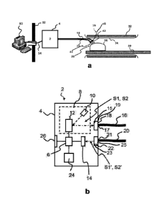
Fig. la schematically illustrates a medical scanner 30 for use with the method
and
apparatus. The scanner 30 is an MR scanner comprising a permanent magnet 32 in
a
scanner housing 34 forming a scanner borehole 36. The scanner 30 comprises a
head
coil 38 for scanning a subject positioned on the support structure (scanner
bed) 39.
First lens assembly 42 and second lens assembly 44 are mounted to respective
distal
ends of first optical fibers 16 and second optical fibers 20 and positioned in
the scanner
borehole 36 for projecting and detecting pattern sequences on/from a surface
region
within the head coil 38.
As an alternative to the MR scanner shown in fig. la, PET scanner comprising
at least
one detector ring in a scanner housing forming a scanner borehole could also
be
imagined. In this case, the distal ends of the respective optical fibers 16,20
could be
positioned outside the detector ring and near the scanner borehole for
projecting and
detecting pattern sequences on/from a surface region within the scanner
borehole. Yet
an alternative to the MR scanner of Fig. la is a combined MR/PET scanner.
Fig. la shows a surface scanning apparatus 2 which is positioned inside the
scanner
room defined by surrounding walls 52 illustrated by one wall/Faraday cage to
the left
side of the apparatus 2. A power management and/or controller part 50, e.g. a
computer as illustrated in Fig. la, is positioned outside the scanner room.
The surface
scanning apparatus 2 may be positioned outside the scanner room defined by
surrounding walls 52 if the optical fibers 16, 20 are sufficiently long.
In Fig. la is also shown an optical extender 54 which transfers image data
noiseless
between the surface scanning apparatus 2 and the computer 50 outside the
scanner
room. The apparatus 2 can be surrounded by a housing 4 which functions as a
radio
frequency shielded box. The housing 4 can be made out of a frame, e.g. a
wooden
frame, covered by a 1 mm copper layer. A filter of capacitors (not shown in
the figure)
ensures that the electromagnetic noise from powering the components inside the
housing does not propagate along the power cable. The power supply optionally
being
a separate power supply or a part of the power management/controller part 50
is
CA 02929677 2016-05-04
WO 2015/071369
PCT/EP2014/074509
12
positioned outside the scanner room and the power is led through a filter in
the wall 52
into the scanner room and the elements inside the housing 4 of the apparatus
2.
The distal ends of fibers are provided with respective first and second lens
assemblies
42, 44 constituting projection optics and image capturing optics,
respectively. A frame
46 is used for fixing the position between the first and second lens
assemblies 42, 44
and/or between the distal ends of the first and second optical fibers 16, 18,
respectively.
The first and second lens assemblies may each comprise an objective lens with
a
given focal length and aperture. Also, the second lens assembly may comprise a
near
infra-red (NIR) filter. Both first and second lens assemblies may comprise a
first
mirror/prism and/or second mirror/prism, respectively. The mirror/prism may be
shared
between the two lens assemblies.
Fig. lb schematically shows a surface scanning apparatus 2 of the present
invention.
The apparatus 2 comprises a housing 4 accommodating a control unit 6 and an
image
source 8 comprising a light source 10 and a light modulator 12. Further, the
apparatus
2 optionally comprises a first camera 14 connected to the control unit 6 for
exchange of
control signals and/or pattern sequence data between the control unit 6 and
the first
camera 14. During use, first optical fibers 16 are coupled to the apparatus at
the
proximal ends 17 of the first optical fibers via first optical coupler 18 such
that light from
the image source 8 is coupled into the first optical fibers 16. The first
optical coupler 18
has a proximal end 15 and a distal end 19.
The apparatus optionally comprises a memory unit 24 and a user interface unit
26.
The first optical fibers 16 may be fixedly mounted to the housing 4, i.e. the
first optical
fibers 16 may form a part of the apparatus 2. Alternatively, a distal end 19
of the first
optical coupler 18 may be secured releasably to the proximal ends 17 of the
first fiber
bundle 16 by a click-release-coupling.
During use, second optical fibers 20 are coupled to the apparatus 2 at the
proximal
ends 21 of the second optical fibers 20 via second optical coupler 22 such
that pattern
sequences or images projected on the surface region is detected by the first
camera
14. The second optical coupler 18 comprises a proximal end 23 and a distal end
25.
The first and second optical fibers may be fixedly mounted to the housing 4,
i.e. the first
and second optical fibers may form a part of the apparatus 2, thereby
simplifying
setting up the apparatus.
CA 02929677 2016-05-04
WO 2015/071369
PCT/EP2014/074509
13
Alternatively, the distal end 19 of the first optical coupler 18 and/or the
distal end 25 of
the second optical coupler 22 may be secured releasably to the proximal ends
17 of
the first fiber bundle 16 and the proximal ends 21 of the second fiber bundle
20,
respectively, by a click-release-coupling.
The apparatus 2 is configured for projecting a first pattern sequence (Si)
onto a
surface region of the subject with the image source 10, wherein the subject is
positioned in a scanner borehole of a medical scanner, the first pattern
sequence
optionally comprising a first primary pattern (P1,1) and a first secondary
pattern (P1,2).
The apparatus 2 may be configured for detecting the projected first pattern
sequence
(51') with the first camera 14. The control unit 6 optionally determines a
second pattern
sequence (52) comprising a second primary pattern (P2,1) based on the detected
first
pattern sequence (Si') and sends control signals to the image source 8 with
image
source 10 and light modulator 12 projecting images in the form of the second
pattern
sequence (52) onto a surface of the subject via the first optical coupler 18.
The
projected second pattern sequence (52') may be detected with the first camera
14 and
the pattern sequence data are processed in the control unit and/or in the
first camera
14 and/or in external computer 50. Upon or during detection of pattern
sequence data,
the apparatus 2 or external computer 50 determines motion tracking parameters
based
on the detected second pattern sequence (52').
Figs. 2-5 show different embodiments of the first optical coupler 18
comprising a
plurality of lens elements /1, /N, including a first lens element /1 and a
second lens
element /2. In Fig. 2, two lens elements are provided whereas Figs. 3 and 4
show a
large plurality of lens elements. In Fig. 5, the first optical coupler 18 is a
relay lens
coupler comprising or consisting of a number of N lens elements positioned
inside an
outer housing of the relay lens coupler. N may be six, eight or ten.
Figs. 2-5 show only the first optical coupler 18, however the second optical
coupler 22
may have an identical or different construction as the embodiments shown in
Figs. 2-5
for the first optical coupler 18. The following description of the lens
elements in the first
optical coupler 18 may therefore also apply to the lens elements in the second
optical
coupler 22.
Each lens element of the plurality of lens elements /1, , /N comprises a
primary surface
28 facing a distal end 19 of the first optical coupler 18, and a secondary
surface 29
facing a proximal end 15 of the first optical coupler 18. Normally, there will
be an even
number of lens elements in the first and/or second optical coupler 18, 22.
There may
be two, four, six, eight, ten, twelve or more lens elements /1, , /N.
CA 02929677 2016-05-04
WO 2015/071369
PCT/EP2014/074509
14
One or more of the lens elements /N may be achromatic, e.g. at least one of
the
plurality of lens elements is achromatic. In Fig. 2-5 only chromatic lens
elements are
shown.
In one or more embodiments, the first lens element /1 is positioned at the
proximal end
15 of the first optical coupler 18 and the second lens /2 element is
positioned at the
distal end 19 of the first optical coupler 18, as shown in Fig. 2. In Fig. 2,
both lens
elements are chromatic. However, the first lens element /1 and the second
element /2
could also be achromatic with convex sides pointing towards each other.
In the apparatus, mirrors and/or prisms may be used to guide the image from
the
image source 8 to the first optical coupler 18. In Figs. 2 and 3, a mirror 7
is used for
guiding the image from the image source to the light modulator 12 from where
it is
guided to the proximal end 15 of the first optical coupler 18. In Figs. 4 and
5, the image
passes from the image source 8 through a prism 9 to the light modulator 12
from where
it again passes through the prism 9 in such a manner that the image is guided
directly
into the proximal end 15 of the first optical coupler 18.
The first and/or second optical coupler 18, 22 may be adapted for either
increasing or
decreasing the size of the image and/or the projected image, respectively such
that the
size of the image / projected image is either larger or smaller after having
passed
through the first and/or second optical coupler.
A simple schematic illustration of how the image size can be increased or
decreased
using an optical coupler is shown in Fig. 6a-b. In Fig. 6a, the image size is
decreased
from a size d,n of the incoming image to a size of dont of the outcoming
image, where d,n
> dont, whereas in Fig. 6b, the image size is increased from d,n of the
incoming image to
a size of dont, where d,n > dont. The different focal length f1, f2 of the
lens elements are
illustrated in the figures.
By utilizing more than two lens elements, an improved correction and reduced
(geometric) distortion may be obtained. Further, aberration effects are
reduced. This
allows the user to control the how large a part of the image which is coupled
into the
first optical fibers 16 and control the size of the projected image, which
comes out of
the second optical coupler 22 after having been collected by the second
optical fibers
20.
Figs. 7a-b show two different examples of a relay lens couplers which may be
used in
the invention as the first optical coupler 18 and/or the second optical
coupler 22.
CA 02929677 2016-05-04
WO 2015/071369
PCT/EP2014/074509
In Fig. 7a, the relay coupler comprises or consist of six lens elements Ii,
/2, /3, /4, /5, /6
arranged symmetrically such that the outermost lens elements /1, /6 are nearly
identical
in size oriented such that they are a mirror image each other. Likewise, the
lens
elements /2, /5 positioned adjacent to the outermost lens elements /1, /6 form
a mirror
5 image pair and so forth for the next lens elements approaching the middle
of the relay
lens coupler. Four of the lens elements /1, /3, /4, /6 are planoconvex, i.e.
they have a
convex side and a plane side, whereas the other two lens elements /2, /5 are
biconcave,
i.e. both the primary and the secondary side of the lens elements are concave.
Fig. 7b shows a relay lens coupler comprising ten lens elements /1, /2, /3,
/4, /5, /6, /7, /8, /9,
10 6 again arranged symmetrically with the lens elements pair wise from the
two
outermost lens elements towards the centre of the relay lens coupler being
mirror
images of one another. In Fig. 7a, four of the lens elements /1, /4, /7, 6 are
planoconvex, two of the lens elements /3, /8 are biconcave, two of the lens
elements /2,
/9 are biconvex, i.e. both the primary and the secondary side of the lens
elements are
15 convex, and the last two elements /5, /6 are planoconcave, i.e. they
have a concave
side and a plane side.
The number of lens elements pairs is not limited to the examples shown in Fig.
7a-b.
Further the combination of sizes and shapes of the lens elements may also
vary, e.g.
different combinations of planoconcave, planoconvex, biconcave, and/or
biconvex lens
element pairs positioned such they form a mirror image of one another could
also be
imagined.
It should be noted that in addition to the exemplary embodiments of the
invention
shown in the accompanying drawings, the invention may be embodied in different
forms and should not be construed as limited to the embodiments set forth
herein.
Rather, these embodiments are provided so that this disclosure will be
thorough and
complete, and will fully convey the concept of the invention to those skilled
in the art.
CA 02929677 2016-05-04
WO 2015/071369
PCT/EP2014/074509
16
REFERENCES
2 Apparatus
4 Housing
6 Control unit
7 Mirror
8 Image source
9 Prism
Light source
12 Light modulator
10 14 First camera
Proximal end of the first optical coupler
16 First optical fibers
17 Proximal ends of first optical fibers
18 First optical coupler
15 19 Distal end of the first optical coupler
Second optical fibers
21 Proximal ends of second optical fibers
22 Second optical coupler
23 Proximal end of the second optical coupler
20 24 Memory
Distal end of the second optical coupler
26 User interface
28 Primary surface of the lens elements
29 Secondary surface of the lens elements
25 30 Medical scanner
32 Magnet
34 Scanner housing
36 Scanner borehole
38 Head coil
39 Scanner bed
Subject
42 First lens assembly
44 Second lens assembly
46 Frame
35 50 Power management part
52 Wall surrounding the scanner room
CA 02929677 2016-05-04
WO 2015/071369
PCT/EP2014/074509
17
54 Optical extender
/N N'th lens element
Ii First lens element
/2 Second lens element
/3 Third lens element
/4 Fourth lens element
/5 Fifth lens element
/6 Sixth lens element
/7 Seventh lens element
/8 Eights lens element
/9 Ninths lens element
/10 Tenths lens element
din Size of the image before entering the first/second optical coupler
dont Size of the image after exiting the first/second optical coupler
f1 Focal length of the first lens element
f2 Focal length of the second lens element