Note: Descriptions are shown in the official language in which they were submitted.
CA 02929752 2016-05-05
1
Process and device for the steam reforming and steam cracking of hydrocarbons
Description
The invention relates to a furnace, in particular for the cracking of
hydrocarbons for
producing olefins, and also to a reformer for hydrogen generation via the
steam
reforming of methane in accordance with Claim 1, and also a process for
bringing a
material stream flowing in a furnace to, and maintaining it at, a temperature,
according
to Claim 9.
Steam reforming of methane for hydrogen generation is a known process. In such
a
process, a warmed material stream is passed through a bundle of reactor tubes,
which
bundle is situated in a fire box (also termed firing chamber) of a furnace.
The material
stream in this case contains the methane-containing feed, and also steam. The
introduction of the material stream into such a furnace proceeds preferably by
conducting into the fire box the reactor tubes via the ceiling of a vertically
extending fire
box, and passing them out again from the fire box at the opposite base. In
order to heat
the material stream, on the ceiling of the fire box, generally burners are
provided which
generate very high temperatures (for example up to 1800 C in the flame)
locally in the
furnace. The reactor tubes of the tube bundle therefore consist of a
correspondingly
heat-resistant material in order that they can withstand these extreme
radiation
conditions. The gas burners are operated usually in flame operation, which
leads to an
inhomogeneous temperature distribution developing in the fire box, wherein the
temperature decreases downwards from the ceiling of the fire box.
The steam cracking of hydrocarbons is likewise a known process. In such a
process, a
warmed material stream is passed through a bundle of reactor tubes which are
situated
in a fire box of a furnace. The material stream in this case contains the
gaseous
hydrocarbon-containing feed, and also steam. The material stream is introduced
into
such a furnace preferably by conducting the reactor tubes through the ceiling
of a
vertically extending fire box into the fire box and conducting them upwards
again in a
bend tightly above the opposite base, and passing them out of the fire box.
For heating
the material stream, on the base and/or on the side wall of the fire box,
burners are
generally provided which generate very high temperatures (for example up to
2000 C
in the flame) locally in the furnace. The reactor tubes of the tube bundle
therefore
CA 02929752 2016-05-05
2
consist of a correspondingly heat-resistant material in order that they can
withstand
these extreme radiation conditions.
On entry of the material stream into the fire box, the reactor tubes are first
protected
against overheating by the comparatively cold material stream. In the further
course,
the material stream heats up so intensely that it can no longer cool the tubes
sufficiently, in such a manner that the temperature of the firing must be
restricted in
order not to overheat the tubes. The temperature course in the material stream
is, inter
alia, dependent on the flow velocity of the material stream, the temperature
profile in
the fire box and other factors, such as, for example, the type and amount of
catalyst
material arranged in the tubes. Reaction conditions, in particular with
respect to the
temperature course in the fire box, are variable only to a limited extent as a
result of
these factors, inter alia, also because the reactor tubes must not be
overheated. The
result, moreover, is that the efficiency of the energy transfer owing to the
given
temperature differences between firing and material stream is limited at the
tubes. For
both processes, a high degree of energetic efficiency is of great importance
for
economic reasons, for which reason some effort is made in order to utilize the
waste
heat of burnt fuel.
Proceeding herefrom, the object of the present invention is to specify a
device and a
process to permit more flexible handling of the reaction dynamics in the
material
stream with simultaneously high energetic efficiency, and at the same time
ensure
sufficient protection of the reactor tubes against overheating.
This problem is solved by a furnace having the features of Claim 1 and also a
process
having the features of Claim 9. Advantageous developments of the invention are
specified in the respective subclaims and are described hereinbelow.
According to Claim 1, it is provided according to the invention that the
furnace has at
least one second combustion chamber, wherein the at least one reactor tube is
also
conducted through the at least one second combustion chamber, wherein the
furnace
is designed to adjust, in each case separately, a first temperature which can
be
generated in the first combustion chamber and a second temperature which can
be
generated in the at least one second combustion chamber.
CA 02929752 2016-05-05
3
Via this multichamber principle, in particular the temperature courses in the
material
stream may be adjusted better, since the ambient temperature in the at least
one
second combustion chamber is separately adjustable, and therefore a
temperature
difference between a reactor tube and the at least one further combustion
chamber is
presettable. As a result, in particular the protection of the reactor tube
against
overheating can be ensured. At the same time, the possibility of temperature
control of
the material stream in a reactor tube is obtained. The furnace can of course
have a
plurality of reactor tubes for conducting/heating the material stream, which
reactor
tubes can form a tube bundle.
In a preferred variant of the invention, it is provided that the at least one
reactor tube is
conducted through the combustion chambers in such a manner that a material
stream
flowing therein is conducted first through the first, and then through the at
least one
second, combustion chamber and possibly further combustion chambers.
In a preferred embodiment of the invention, the furnace has at least one first
burner
which is designed for heating a material stream flowing in the at least one
reactor tube
to burn a fuel, generating a flame in the first combustion chamber. The
furnace can
also have a plurality of such first burners in the first combustion chamber.
In a preferred variant of the invention, the furnace has at least one second
burner,
which is designed to oxidize flamelessly a fuel in the at least one second
combustion
chamber (what is termed an FLX burner).
Here also, optionally a plurality of such second burners can be provided in
the second
combustion chamber (or optionally further combustion chambers).
Such a flameless oxidation (FLX) is distinguished, for example, by the
reduction of the
formation of nitrogen oxides. By means of such second burners, via a high
entry
impulse of the air stream, a good flue gas mixing is generated, which leads to
a
homogeneous temperature distribution in the corresponding combustion chamber.
In a preferred embodiment of the invention, it is provided that the at least
one first
burner is arranged in particular on a ceiling or on a base of the first
combustion
chamber, wherein, in particular, the entry of the at least one reactor tube
into the first
combustion chamber is made on that side of the first combustion chamber on
which the
CA 02929752 2016-05-05
4
at least one first burner is also arranged, and wherein, in particular, the at
least one
reactor tube exits from the first combustion chamber on that side which is
opposite the
at least one first burner.
In a further preferred embodiment of the invention, the furnace has a fire box
which is
subdivided via at least one wall of the fire box into the first and the at
least one second
combustion chamber. Alternatively, there is of course also the possibility of
providing
completely separate combustion chambers in the form of separate fire boxes.
Preferably, the first and the at least one further combustion chamber share,
in
particular, a common wall. In the case of a plurality of combustion chambers
in the form
of separate units, the combustion chambers are connected by the reactor tubes
which
run between the units.
In a preferred variant of the invention, the furnace is designed in such a
manner that
the first temperature that can be generated in the first combustion chamber is
higher
than the second temperature that can be generated in the at least one second
combustion chamber. Since the temperature distribution in the first combustion
chamber, owing to the arrangement of the first burner, generally turns out in
a
heterogeneous manner, the first temperature relates in particular to the
region of the
flame of the at least first burner.
Preferably, the furnace is in addition designed in such a manner that a
homogeneous
second temperature is adjustable in the at least one second combustion
chamber. This
is the case in particular when the at least one second combustion chamber is
heated
by the abovedescribed FLX process.
As mentioned above, in particular second burners in the form of FLX burners
are
suitable for developing a spatially homogeneous temperature profile which need
not be
the case with a burner operated in flame mode.
In addition, the object in question is achieved by a process for bringing to,
and holding
at, a temperature of a material stream flowing in a flow direction in at least
one reactor
tube of a furnace, in particular using a furnace according to the invention,
wherein the
material stream flowing in the at least one reactor tube is exposed in a first
combustion
CA 02929752 2016-05-05
chamber to a separately adjustable first temperature and subsequently in at
least one
second combustion chamber for protection of the at least one reactor tube
against
overheating is exposed to a separately adjustable second temperature.
5 In a preferred embodiment of the invention, a homogeneous second
temperature is set
in the at least one second combustion chamber. In this case, in particular in
the first
combustion chamber, the material stream flowing in the at least one reactor
tube is
exposed to a first temperature decreasing in the direction of flow, wherein
the
maximum of the first temperature is in particular markedly higher (several 100
K) than
the second temperature.
The process according to the invention may be applied to various processes in
furnaces.
For instance, in a preferred embodiment of the invention it is provided that
the material
stream hydrocarbon compounds and steam, optionally with the use of suitable
catalysts, are reacted in the furnace to form hydrogen and carbon oxides. This
chemical reaction is widely known summarized under the expression steam
reforming.
As catalysts, preferably nickel- or noble metal-based catalyst materials are
used.
In a further preferred variant of the invention it is provided that the
material stream
contains relatively long-chain hydrocarbon compounds, in particular naphtha,
propane,
butane and or ethane, and water, wherein the hydrocarbon compounds are reacted
with the water in the furnace to form olefins such as ethene and propene. This
chemical reaction is widely known summarized under the expression steam
cracking.
In a further preferred variant of the invention, the material stream contains
propane
and, in particular, steam, wherein the propane, optionally in the presence of
corresponding catalysts, is reacted in the furnace to form propene in the
context of a
propane dehydrogenation reaction.
Further features and advantages of the invention are described in the
exemplary
embodiments shown schematically hereinafter in Figures 1 and 2. In the
drawings:
Fig. 1 shows a schematic image of a furnace according to the invention; and
CA 02929752 2016-05-05
6
Fig. 2 shows a further embodiment of a furnace according to the
invention.
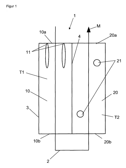
Figure 1 shows a schematic depiction of a furnace 1 according to the
invention. A
material stream M in this case, in at least one reactor tube 2, or a reactor
tube bundle
2, is introduced into the first combustion chamber 10 through the ceiling 10a
of a first
combustion chamber 10. On the ceiling 10a of the first combustion chamber 10,
at
least one first burner 11 is provided which, in this example, oxidizes a fuel
with
formation of a flame. In the first combustion chamber 10, the material stream
M heats
up. The at least one reactor tube 2 leaves the first combustion chamber 10
through the
base 10b of the first combustion chamber 10 that is opposite along the
vertical the
ceiling 10a and enters, through the base 20b of a second combustion chamber
20, into
said second combustion chamber 20. In this second combustion chamber 20, two
second burners in the form of FLX burners 21 are arranged, in particular,
diagonally
opposite one another, which burners are preferably designed to generate a
comparatively homogeneous spatial temperature profile in the second combustion
chamber 20. The material stream M which, in this section, may consist partly
of reagent
and product (see also the abovedescribed uses of the process), exits from the
furnace
1 through the ceiling 20b of the second combustion chamber 20 and is passed on
further from there in order possibly to be further processed. It should be
noted that in
this example, the first and the second combustion chambers 10, 20 are formed
by one
fire box 3 which is subdivided into the two combustion chambers 10, 20 by a
central,
vertically running wall 4 of the fire box 3, in such a manner that the two
combustion
chambers 10, 20 are laterally adjacent to one another. Further combustion
chambers in
the form of the second combustion chamber 20 can be provided which can be
connected, e.g. laterally, to the one second combustion chamber 20.
In Figure 2, as in Figure 1, the material stream M is first conducted through
a first
combustion chamber 10 of the type of Figure 1, which is likewise heated in the
flame-
oxidation mode, before the material stream M enters a second combustion
chamber 20
which is heated in the FLX process. However, in this case, the material stream
M (and
the at least one reactor tube 2) enters the second combustion chamber 20
through the
ceiling 20a of the second separate combustion chamber 20 and exits again at
the base
20b thereof. The dotted depiction of the at least one reactor tube 2 indicates
a region or
a module 100 of the furnace 1, which can be serially connected as often as
desired at
CA 02929752 2016-05-05
7
this point. This module 100 has a section of the at least one reactor tube 2
(which is
shown dotted) and the said second combustion chamber 20. In each further
module,
the temperature can be controlled separately. After passing through a last
combustion
chamber 50, the material stream M exits therefrom and can be appropriately
further
processed. This system is an optimization of conventional furnaces. A
modification of
the arrangement according to Figure 2 can provide that the combustion chambers
10,
20, 50 again proceed from a single fire box by subdivision of the fire box by
means of
walls of the fire box.
CA 02929752 2016-05-05
8
List of reference signs
1 Furnace
2 Reactor tube/tube bundle
3 Fire box
4 Dividing wall of two combustion chambers
First combustion chamber
10a Ceiling of the first combustion chamber
10b Base of the first combustion chamber
11 Burner of the first combustion chamber
Second combustion chamber
20a Ceiling of the second combustion chamber
20b Base of the second combustion chamber
21 FLX burner of the second combustion chamber
50 A last combustion chamber
100 Combustion chamber module
M Material stream
T1 First temperature
T2 Second temperature